Page 237 of 425

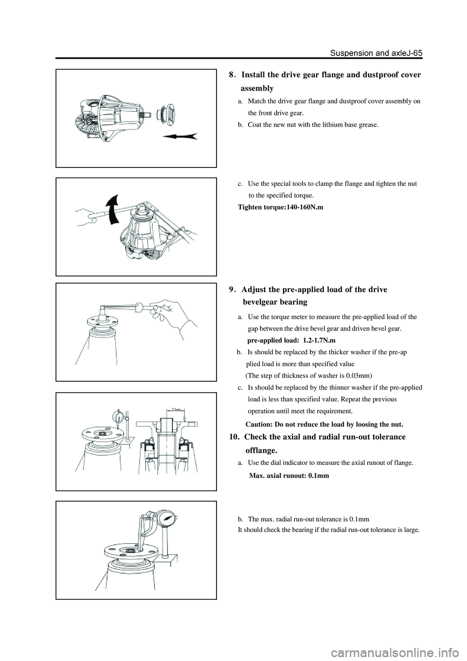
8Install the drive gear flange and dustproof cover
assembly
a. Match the drive gear flange and dustproof cover assembly on
the front drive gear.
b. Coat the new nut with the lithium base grease.
c. Use the special tools to clamp the flange and tighten the nut
to the specified torque.
Tighten torque:140-160N.m
a. Use the torque meter to measure the pre-applied load of the
gap between the drive bevel gear and driven bevel gear.
pre-applied load: 1.2-1.7N.m
b. Is should be replaced by the thicker washer if the pre-ap
plied load is more than specified value
(The step of thickness of washer is 0.03mm)
c. Is should be replaced by the thinner washer if the pre-applied
load is less than specified value. Repeat the previous
operation until meet the requirement.
Caution: Do not reduce the load by loosing the nut.
10. Check the axial and radial run-out tolerance
offlange.
a. Use the dial indicator to measure the axial runout of flange.
Max. axial runout: 0.1mm
b. The max. radial run-out tolerance is 0.1mm
It should check the bearing if the radial run-out tolerance is large.
9Adjust the pre-applied load of the drive
bevelgear bearing
Page 238 of 425
11Rivet the drive gear nut after meet the previ-
ous requirements.
12
Install the reducer assembly on the front drive
axle assembly and assemble the front drive shaft
assembly (refer to Assembly of Front Reducer Assembly
and Assembly of Front Drive Shaft Assembly)
13
Install the oil drain plug; screw off the oil
filling plug and filled with the hypoid gear oil.
Tightening force of oil drain plug: 30-35Nm
Model of lubrication oil: GL-5
Filling amount: Flush to the lower edge of oil filling open
14Insert the oil filling plug washer and tighten
the oil filling plug to the specified torque.
Specified torque : 140-150Nm
15Install the front drive axle assembly on the
carriage.
16
Connect the drive shaft to the flange
a. Align the assembly mark; use four bolts and nuts to connect
the flange of drive shaft and front drive axle.
b.Tighten the nut to the specified torque.
specified torque:
Remarks: Keep the clean of the field during the maintenance.
Page 241 of 425
8. Use the jack to support the front reducer assembly
9. Remove the lifting bolt of front drive axle hanger
plank and carriage.
10. Remove the front drive axle assembly
Caution: Do not damage the drive shaft and front drive
shaft jacket
11. Remove the front drive shaft assembly of both sides
from the front drive axle assembly.
12. Use the wrench to remove the bolt and nut which is
used to fix the front reducer housing.
13. Remove the clump weight assembly and clump
weight bracket welded assembly
(Refer to “Disassembly of Front Reducer Assembly”)
electric clutch connector
N
m: specified torque
Page 242 of 425
Replacement of front reducer assembly oil seal
1. Remove the front drive axle assembly
(Refer to “Removal of Front Reducer Assembly”)
2. Remove the left and right front drive shaft assem-
bly from the front drive axle assembly.
3. Remove and replace the lower oil seal according to
the removal and installation procedure of front drive
shaft assembly and install the new side oil seal on
the front drive shaft, then install them in the front
reducer assembly.
(Refer to “Removal and Installation of Front Drive Shaft
Assembly”)
Replacement of oil seal and major semiaxle oil seal of front reducer assembly
major semiaxle oil seal
major semiaxle pressing assembly
circlip
mechanical wheel of separator
Pregummed component N
m: Specified torque
Page 246 of 425

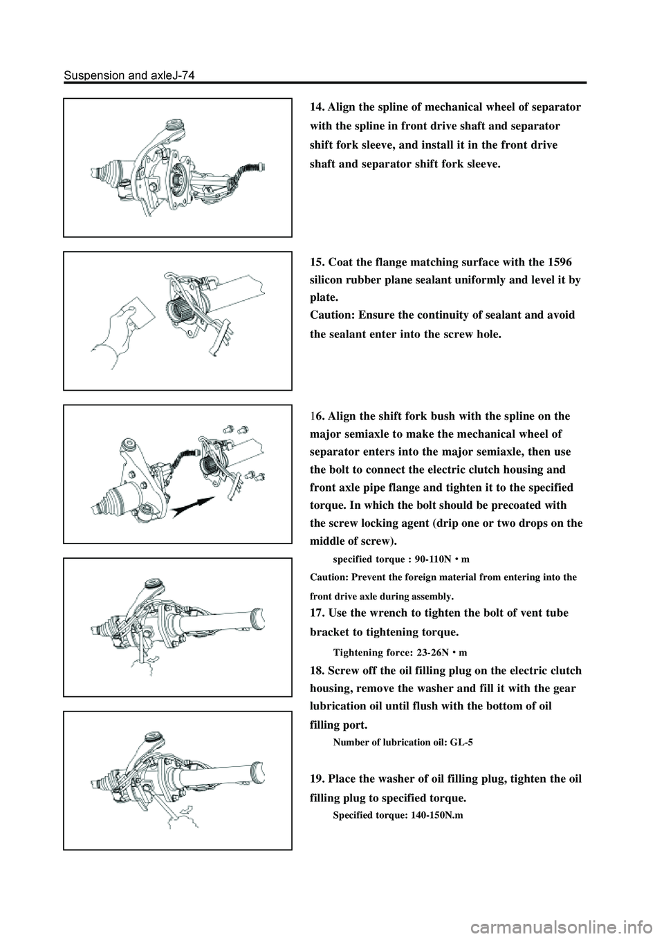
14. Align the spline of mechanical wheel of separator
with the spline in front drive shaft and separator
shift fork sleeve, and install it in the front drive
shaft and separator shift fork sleeve.
15. Coat the flange matching surface with the 1596
silicon rubber plane sealant uniformly and level it by
plate.
Caution: Ensure the continuity of sealant and avoid
the sealant enter into the screw hole.
16. Align the shift fork bush with the spline on the
major semiaxle to make the mechanical wheel of
separator enters into the major semiaxle, then use
the bolt to connect the electric clutch housing and
front axle pipe flange and tighten it to the specified
torque. In which the bolt should be precoated with
the screw locking agent (drip one or two drops on the
middle of screw).
specified torque : 90-110Nm
Caution: Prevent the foreign material from entering into the
front drive axle during assembly.
17. Use the wrench to tighten the bolt of vent tube
bracket to tightening torque.
Tightening force: 23-26Nm
18. Screw off the oil filling plug on the electric clutch
housing, remove the washer and fill it with the gear
lubrication oil until flush with the bottom of oil
filling port.
Number of lubrication oil: GL-5
19. Place the washer of oil filling plug, tighten the oil
filling plug to specified torque.
Specified torque: 140-150N.m
Page 248 of 425
Disassembly and assembly of front reducer assembly and electric clutch
adjusting shim
bearing gland
differential housing
driven bevel gear
front drive axle housing
washer
oil filling plug
vent tube
clip
front axle vents tube
connector assembly
major semiaxle
needle bearingelectric clutch
location pin
vent tube
mechanical wheel of separator
declutch shift sleeve
electric clutch housing
oil filling plug
circlip
major semiaxle oil seal
half axle gear thrust plate
half axle gear
planetary gear shaft
planetary gear
bolt clump
weight bracketclump weight and bush
assembly
clump weight bracket
welded assembly
front reducer
housing
adjusting washerspacer
drive bevel gear
small bearingoil sealfront drive gear flange and
dustproof cover assembly
drive bevel gearadjusting washer
Pregummed component
N m: Specified torque
Used component which
can not be used any more.bearing
circlip
big bearing
Page 252 of 425
20. Check the engaging mark of drive and driven
bevel gear.
(Refer to “Assembly of Front Reducer Assembly”)
21. Measure the pre-applied load of drive bevel gear
bearing.
Use the torque measuring meter to measure the preapplied
load on the gap between the drive and drivenbevel gear.
Range of pre-applied load: 1.2-1.7N.m
22. Measure the total pre-applied load of drive bevel
gear.
23 Remove the drive gear flange and dustproof cover
assembly.
a. Use the hand hammer and chisel to loose the riveted part of
drive gear nut.
b. Use the special tools to clamp the drive gear flange and
remove the drive gear nut.
c. Use the brass rod to knock down the drive gear flange and
dustproof cover assembly.
Page 257 of 425

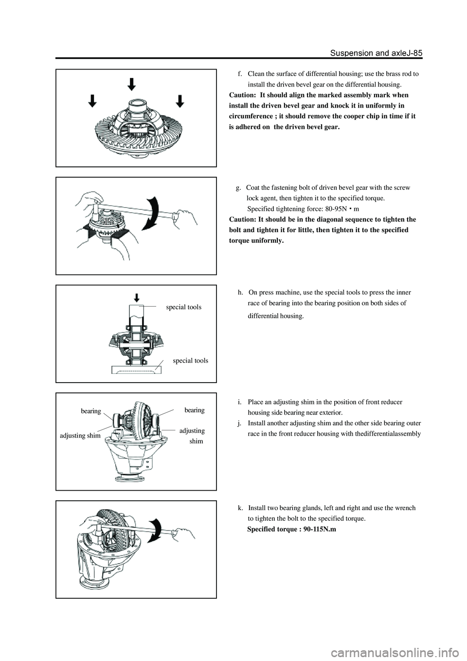
f. Clean the surface of differential housing; use the brass rod to
install the driven bevel gear on the differential housing.
Caution: It should align the marked assembly mark when
install the driven bevel gear and knock it in uniformly in
circumference ; it should remove the cooper chip in time if it
is adhered on the driven bevel gear.
g. Coat the fastening bolt of driven bevel gear with the screw
lock agent, then tighten it to the specified torque.
Specified tightening force: 80-95N
m
Caution: It should be in the diagonal sequence to tighten the
bolt and tighten it for little, then tighten it to the specified
torque uniformly.
h. On press machine, use the special tools to press the inner
race of bearing into the bearing position on both sides of
differential housing.
i. Place an adjusting shim in the position of front reducer
housing side bearing near exterior.
j. Install another adjusting shim and the other side bearing outer
race in the front reducer housing with thedifferentialassembly
k. Install two bearing glands, left and right and use the wrench
to tighten the bolt to the specified torque.
Specified torque : 90-115N.m
special tools
special tools
bearingbearing
adjusting shimadjusting
shim