2006 GREAT WALL HOVER wheel
[x] Cancel search: wheelPage 8 of 425

Instroduction-6
9. Determine the necessity of using special maintenance tools and
special maintenance material according to the practical situation
of maintenance. Use them on the necessary position, and go on
with the maintenance according to proper procedures.
10. To replace the fuse, check to see whether the rated current of
new fuse is correct. Do not exceed the rated current of the fuse,
or do not use the fuse with low rated current.
11. When jacking up or supporting the car, lift or support the car on
proper position with care.
a. If only jacking up the car in the front part or rear part, choke up the
wheel to ensure the safety.
b. After the car is jacked up, use frame to support it. It is dangerous to
conduct maintenance on the car that is only jacked up with one
screw jack, even for the minor maintenance that can be finished
quickly.
12. Paying attention to the following matters to avoid the damage
of components:
a. If it is not absolutely necessary, do not open the housing of the
ECU and the computers (if the IC terminals are touched, the IC
may have electrostatic damage).
b. When removing the vacuum tube, pull the end of the tube instead of
the central part of the tube.
c. When pulling the wire terminal, pull the terminal itself instead of
the wire.
d. Take care to not make the electrical components fallen, such as the
sensor or relay.
If they fall to the hard ground, they must be replaced.
e. Never use the striking wrench to remove or install the electric
thermostat or thermostat sensor.
f. When checking the conducting state of the wire connector, insert
the multimeter with care, do not bend the terminal.
g. When using the vacuum meter, do not insert the soft tube onto large
connector. Use the stepped terminal. Once the soft tube is swelled
and tightened, there may be leakage.
error correct
Page 10 of 425

Overview of the entire car-1
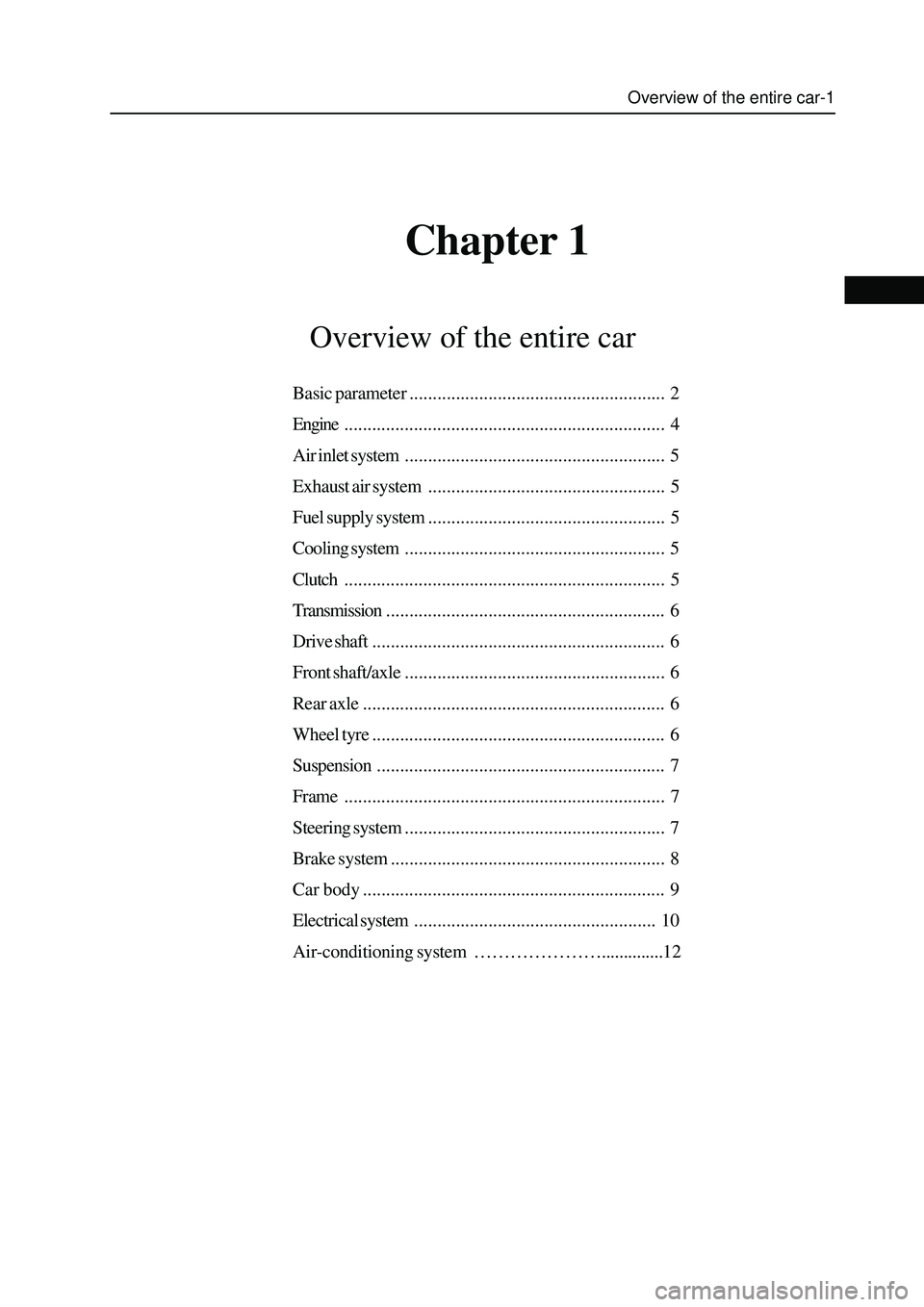
Chapter 1
Overview of the entire car
Basic parameter....................................................... 2
Engine..................................................................... 4
Air inlet system........................................................ 5
Exhaust air system................................................... 5
Fuel supply system................................................... 5
Cooling system........................................................ 5
Clutch..................................................................... 5
Transmission............................................................ 6
Drive shaft............................................................... 6
Front shaft/axle........................................................ 6
Rear axle................................................................. 6
Wheel tyre............................................................... 6
Suspension.............................................................. 7
Frame..................................................................... 7
Steering system........................................................ 7
Brake system........................................................... 8
Car body................................................................. 9
Electrical system.................................................... 10
Air-conditioning system …………………..............12
Page 11 of 425

Basic parameter
The basic parameters of the complete vehicle of CC6460K and CC6460KY estate car should be in accordance with the regulation
in Table 1.
Basic parameters of the complete vehicle of CC6460K and CC6460KY
Item CC6460K CC6460KY
Dimension parameter(no-load)(mm)
L 4620
W 1800
H 1710(car
body)/1755(with
tail fin and
luggage carrier) 1700(car body)/1765(with tail fin
and luggage carrier)
Axle tread 2700
Wheel tread: front/rear 1515/1520
Front suspension 850
Rear suspension 1070
weight parameter:
Loading weight(kg) 5 person × 65kg/person + 150kg
Complete weight(kg) 1720 1830
Max. total weight(kg) 2195 2305
No-load axial load distribution: front/rear(kg) 890/830 980/850
full-load axial load distribution: front/rear(kg) 980/1215 1070/1235
Traffic ability parameter
Min. turning diameter(m) ≤13
Min. ground clearance (mm) ≥180 ≥175
Approach angle(°) ≥28(no-load)
departure angle(°) ≥27.5(no-load)
Dynamic parameter:
Min. stable speed of direct step(km/h) ≤25
30km/h~100km/h acceleration time of direct step(s) ≤32
acceleration time from 1 step starting to 100km/h(s) ≤20
Max. speed(km/h) ≥160
Max. Climbing capability(%) ≥35
Economical character:
Slipping distance in initial speed of 50km/h(m) ≥500
Traveling fuel consumption in 90km/h constant speed (L/100km) ≤10.19
Traveling fuel consumption in 120km/h constant speed (L/100km) ≤13.24
Under simulated urban and suburb comprehensive operating
condition(L/100km) ≤11.9 ≤12.5
Braking characteristics:
Traveling braking distance in 50km/h braking initial speed (m) ≤19(no-load), ≤20(full-load)
Emergency braking distance in 50km/h braking initial speed(m) ≤38
Slop e stop braking(%) ≥20(no-load), ≥18(full-load)
Page 15 of 425

Front shaft/axle
CC6460K wagon has the two-cross arm, independent suspension, breakaway front axle.
CC6460KY wagon has the two-cross arm, independent suspension, breakaway steering drive axle , hyperbolic gear single-stage main
reducer, plain bevel gear differential mechanism, universal drive semiaxle, Birfield ball-joint, main reduction ratio i
0=4.55, Max. input
torque is 900N
m.
Rear axle
Non-breakaway drive axle, integral stamping-welded axle housing, hyperbolic gear single-stage main reducer, plain bevel gear differential
mechanism, semi-floating semiaxle, main reduction ratio i
0=4.55, Max. input torque is 900Nm.
Wheel and tyre
The type, specification and main parameter of wheel and tyre see Table 4.
Table 4 Type, specification and main parameter of wheel and tyre
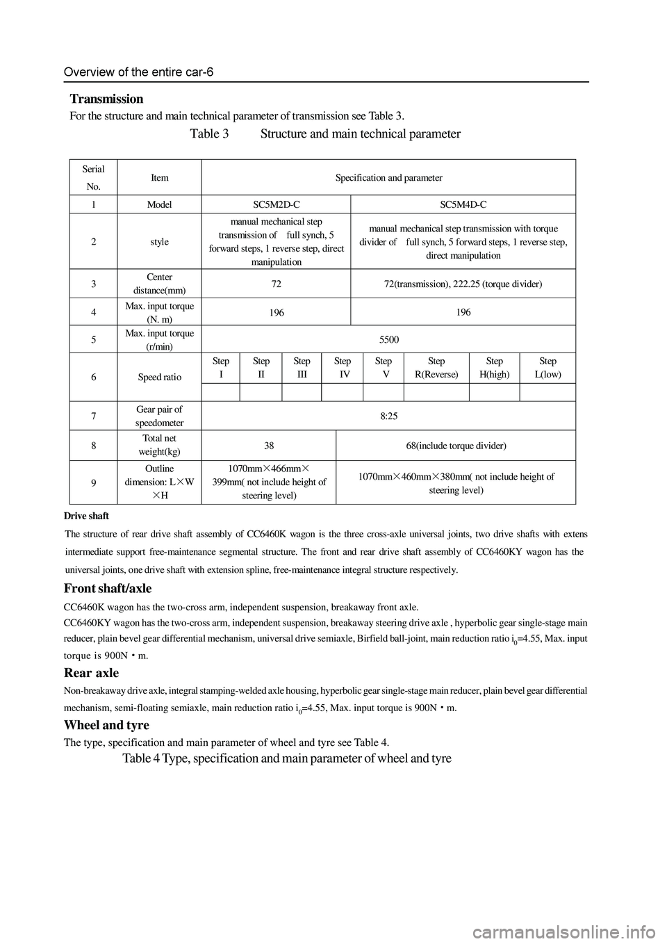
Transmission
For the structure and main technical parameter of transmission see Table 3.
Table 3 Structure and main technical parameter
Serial
No. Item Specification and parameter
1 Model SC5M2D-C SC5M4D-C
2 style manual mechanical step
transmission of full synch, 5
forward steps, 1 revers e step, direct
manipulation manual mechanical step transmission with torque
divider of full synch, 5 forward steps, 1 reverse step,
direct manipulation
3 Cent er
distance(mm) 72 72(transmission), 222.25 (torque divider)
4 Max. input torque
(N. m) 196 196
5 Max. input torque
(r/min) 5500
Step
I Step
II Step
III St ep
IV Step
V Step
R(Reverse) Step
H(high) St ep
L(low)
6 Speed ratio
7 Gear pair of
speedometer 8:25
8 To t a l n et
weight(kg) 38 68(include torque divider)
9 Outline
dimension: L×W
×H 1070mm×466mm×
399mm( not include height of
steering level) 1070mm×460mm×380mm( not include height of
steering level)
Drive shaft
The structure of rear drive shaft assembly of CC6460K wagon is the three cross-axle universal joints, two drive shafts with exten
s
intermediat e support free-maint enance segmental structure. The front and rear dr ive shaft assembly of CC6 460KY wa gon has the
universal joints, one drive shaft with extension spline, free-maintenance integral structure respectively.
Page 16 of 425

Overview of the entire car-7
Suspension
The front suspension is the torsion bar spring, double-cylinder inflatable hydraulic damper, transverse stabilizer rod, double
cross-arm independent suspension. The distance between the center of front shaft of lower arm fixing nut and level ground is
295mm±1mm.
The rear suspension is the four-connecting rod, coil spring, double-cylinder inflatable hydraulic damper, transverse stabilizer
rod, no indep endent suspension.
Carriage
Peripheral trapezoidal structure; welded by two box section longitudinal beams and several box or tube section cross beams.
Steering system
Pinion-and-rack power steering-gear, hydraulic assists steering. Breakaway front steering trapezoidal structure. Diameter of
quadriradistus steering disc φ380mm, adjustable angle, power-absorbing steering pipe. For main technical parameters of
steering s ystem refer to Table 5.
Table 5 Main technical parameter of steering system
Serial No. Item Parameter Serial No. Item Parameter
1 wheel camber 0°±30′ 6 Rotary round of
steering disc n 3.64
2 kingpin inclination 12°30′±30′ 7 Angle drive ratio of
steering system i0ω 18.2
3 kingpin castor 3°30′±30′ 8 Force drive ratio of
steering s ystem i0p 198.0
4 toe (mm) 0~2 9 Normal efficiency of
steering gear η+ ≥75%
5 Steering angle of
internal and external
wheel (°) 32/28 10 Revers e efficiency of
steering gear η- ≥60%
1.Adjustment of .4-Wheel Alignment
Test and adjust the front wheel alignment value and adjust the toe on the 4-Wheel Alignment meter.
a. Adjustment of kingpin castor: The standard value is 3°30′±30′(adjust the difference of left and right kingpin
castor to within 30′);
b. Adjustment of toe: The toe with standard value of 0~2mm is adjusted by rotating the steering cross rod. When adjust
the toe, it should rotate the cross brace in left and right side evenly. Tighten the lock nut after adjustment, the torque is
55 - 65N·m.
c. Centering and fix of steering wheel: according to the display of the alignment gauge, turn the front wheel to right
ahead, after removing the steering wheel without changing the position of steering lever, mount the steering wheel
with center aligned, the radials of the steering wheel shall be in the bilateral symmetry position, and the symbol of
Great wall on the steering wheel shall be in the confrontation position of the driver, tighten the nut, with a tightening
torque of 25 - 35N·m.
Left wheel left steering: 32, right wheel left steering:28;
Left wheel right steering:
28, right wheel right steering: 32;
b. Under the light condition of the car, the height between the center of front axis fixed bolt of the lower suspension arm to the
ground is 295
1mm, if the dimension is not within this scope, reach it through adjusting the torsion bar adjustment arm
bolt;
c. The reference dimension of the height of the car is : the left and right deviation is less than 10mm;
3. Checking the free gap of steering wheel:
Turn the orientation of the car to front, stop the engine, exert a force of about 4.9N on the steering wheel along the circumferential
direction to make the it turning to the left, there is resistance force, stop turning when the resistance force is growing; then turn
the steering wheel to the right, stop turning when the resistance force is felt to be growing; the radian value that the external edge
of steering wheel runs is the free gap of the steering wheel, its standard value shall be less than or equal to 20
, and the corner
from the central position to the left or right shall be no larger than 10.
Page 17 of 425

Brake system
The front wheel brake is ventilation coil type, the rear wheel brake is disk and drum type. The service brake type is that the double-
loop vacuum assist hydraulic brake is applied on the front and rear disc brake. The parking brake is mechanical dragline acting on the
drum brake of the rear wheel.
The free stroke of brake pedal is 20mm
30mm, and the operating stroke of the pedal is 120mm. The operating stroke of the brake
handle is 17
(3 teeth)30(8 teeth).
1. The adjustment of brake pedal
Measure the operating stroke of the brake pedal, the standard value is 120mm. When the eighth is no in compliance with the
requirement, make adjustment according to the following procedures:
a. Separate the brake lamp switch wire connector, loosen the blocking nut, and turn the brake lamp switch to the position that the
stopper is not touched;
b. Unscrew the blocking nut of the operation connecting rod, use the thinnose pliers to turn the operation connecting rod, adjust
the brake pedal height to standard value, after reaching the standard value, tighten the lock nut;
c. Turn the brake lamp switch to the position that the stopper of brake pedal is just touched, continue the turning for 1/2
1 circle,
and tighten the blocking nut;
d. Connect the brake lamp switch wire connector;
e. The brake lamp should not be light when the brake pedal is in release status.
2. Standard value of brake pedal free stroke: 20-30 mm
a. Under the stopping status of the engine, step on the brake pedal for 2
3 times, clear the influence of brake assistor, then use
hand to push the brake pedal to the position that there is resistance, measure the amount of movement (free stroke). It shall
be in compliance with the regulation of standard value;
b. If the gap is less than the regulation value, check to see whether the gap between the carrier rod of brake lamp switch and the
brake pedal is in compliance with the regulation. If this gap is exceeding the regulation, it means that the gap between the drive
rod clevis pin and the brake pedal arm is exceeding the regulated value.
3. Start the engine, step down the brake pedal with a force of about 700N,ehck the main brake pump, whether there is oil
leakage on the connection positions of the brake pipeline. If there is, maintain it.
4. Operating status test of brake assistor
Conduct the operation status test of the brake assistor according to the following methods:
a. Start the engine, stop if after operating for 1
2 minutes. Step on the brake pedal for several times with normal force. Expect
that the pedal can be fully stepped down a the first stepping, the height of the brake pedal shall be raised on and on with the
stepping, thus means that the brake assistor operates normally, if the height of the pedal is not changed, it means that the brake
assistor is damaged;
b. Under the stopping status of the engine, step on the brake pedal for several times, confirms that the height of brake pedal is
elevated on and on, under the status that the brake pedal is stepped down, start the engine. At this time, the brake pedal will
move down a bit, it means that the brake assistor is working normally. If the brake pedal is moving upwards, it means that the
brake assistor is damaged;
c. Under the operation status of the engine, step down the brake pedal to stop the operation of the engine. AT this time, the there
shall be no change of the height of brake pedal within 30 seconds, it means that the brake assistor is working normally. If the
brake pedal is moving upwards, it means that the brake pedal assistor is damaged.
5. Adjustment of the parking brake system:
a.For positioning, pull the brake bar to the limit position for over 3 times, use a force of about 400N to pull the brake parking
lever, count the number of knocking teeth. The standard value of stroke of parking brake : 17
(3 teeth) 30(8 teeth);
b.If the stroke of brake parking lever is too big and not in compliance with the requirement, adjust it with the following methods:
Loosen the brake parking lever, unscrew the adjusting nut.
Remove the adjuster hole cap from the brake assembly, use screwdriver to turn the adjustor in the arrow direction to the limit
that the brake drum cannot turn.
Rotate 5 teeth in the counter arrow direction.
Rotate the adjusting nut, adjust the brake parking lever stroke to the standard value.
c. If the stroke is less than the standard value, unscrew the adjusting nut to make it reach the standard value.
d. Check to see whether the adjusting nut and the rod are loosened, whether the adjusting nut is fixed in the fixed seat.
e. After adjustment, jack up the rear part of the car. Loosen the brake parking lever, the brake disc shall not be dragged when
checking the rear wheel.
f. The breaking in of the parking brake: use the force of about 200-250N to pull the brake parking lever,drive the car for about
400m with a speed of about 60km/h, repeat for 2-3 times, then test on the slope of 30%, the car shall be able to be parked.
Page 36 of 425

Clutch-6
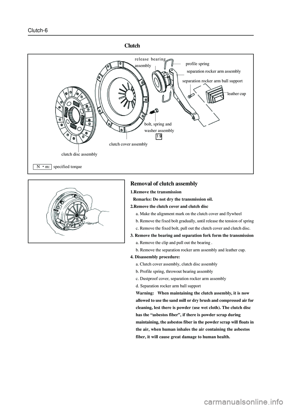
Clutch
4. Disassembly procedure:
a. Clutch cover assembly, clutch disc assembly
b. Profile spring, throwout bearing assembly
c. Dustproof cover, separation rocker arm assembly
d. Separation rocker arm ball support
Warning: When maintaining the clutch assembly, it is now
allowed to use the sand mill or dry brush and compressed air for
cleaning, lest there is powder (use wet cloth). The clutch disc
has the “asbestos fiber”, if there is powder scrap during
maintaining, the asbestos fiber in the powder scrap will floats in
the air, when human inhales the air containing the asbestos
fiber, it will cause great damage to human health.
Removal of clutch assembly
1.Remove the transmission
Remarks: Do not dry the transmission oil.
2.Remove the clutch cover and clutch disc
a. Make the alignment mark on the clutch cover and flywheel
b. Remove the fixed bolt gradually, until release the tension of spring
c. Remove the fixed bolt, pull out the clutch cover and clutch disc.
3. Remove the bearing and separation fork form the transmission
a. Remove the clip and pull out the bearing .
b. Remove the separation rocker arm assembly and leather cup.
clutch disc assembly
clutch cover assembly
bolt, spring and
washer assembly release bearing
assembly
profile spring
separation rocker arm assembly
separation rocker arm ball support
leather cup
N m: specified torque
Page 37 of 425

Clutch-7
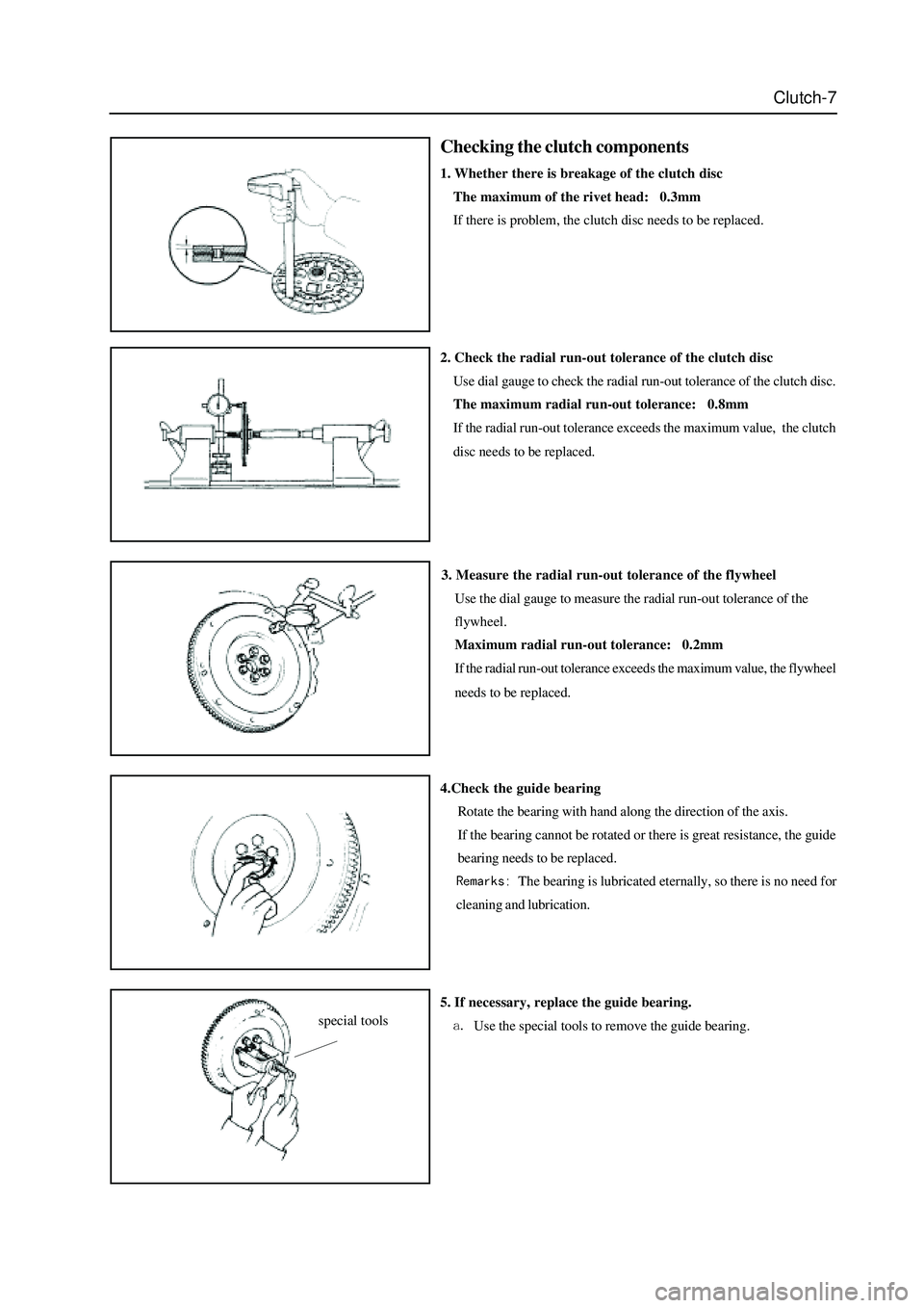
Checking the clutch components
1. Whether there is breakage of the clutch disc
The maximum of the rivet head: 0.3mm
If there is problem, the clutch disc needs to be replaced.
3. Measure the radial run-out tolerance of the flywheel
Use the dial gauge to measure the radial run-out tolerance of the
flywheel.
Maximum radial run-out tolerance: 0.2mm
If the radial run-out tolerance exceeds the maximum value, the flywheel
needs to be replaced.
4.Check the guide bearing
Rotate the bearing with hand along the direction of the axis.
If the bearing cannot be rotated or there is great resistance, the guide
bearing needs to be replaced.
The bearing is lubricated eternally, so there is no need for
cleaning and lubrication. 2. Check the radial run-out tolerance of the clutch disc
Use dial gauge to check the radial run-out tolerance of the clutch disc.
The maximum radial run-out tolerance: 0.8mm
If the radial run-out tolerance exceeds the maximum value, the clutch
disc needs to be replaced.
5. If necessary, replace the guide bearing.
Use the special tools to remove the guide bearing.special tools