Page 23 of 425

Fuel supply system
N m: specified torque
adjustment nut
throttle pull wire
accelerator pedal assembly
carbon tank exhaust rubber tube
snap fitting
steel strip type elastic hoop
generator oil-in rubber tube
generator of return rubber tube
soft tube fixing clipper
carbon
tankcarbon tank
air inlet
rubber tubeb type
worm drive
type hoop
vaporizer tube 2
back part of fuel tank
oil-out tube
back part of fuel tank
oil return tubefuel filter
filter rubber tube
for gas out
hard tube bracketvaporizer soft tube 2 cleaner bracket
filter rubber
tube for gas-in
fuel tank vaporizer
rubber tube
front part of the oil-out
tube of fuel tank
vaporizer soft
tube1vaporizer tube1
fuel tank gland the middle connection rubber
tube of the oil return tube
front taps of fuel tankfuel pumpfuel tank gland
fuel tank protection plateseal packing
ringfuel tank assembly
fuel tank oil return tube
fuel tank lock
refill opening cushion
pressing board
refill opening cushion
oil filing port assembly
steel strip type elastic hoop
fuel tank protection plate
Page 167 of 425

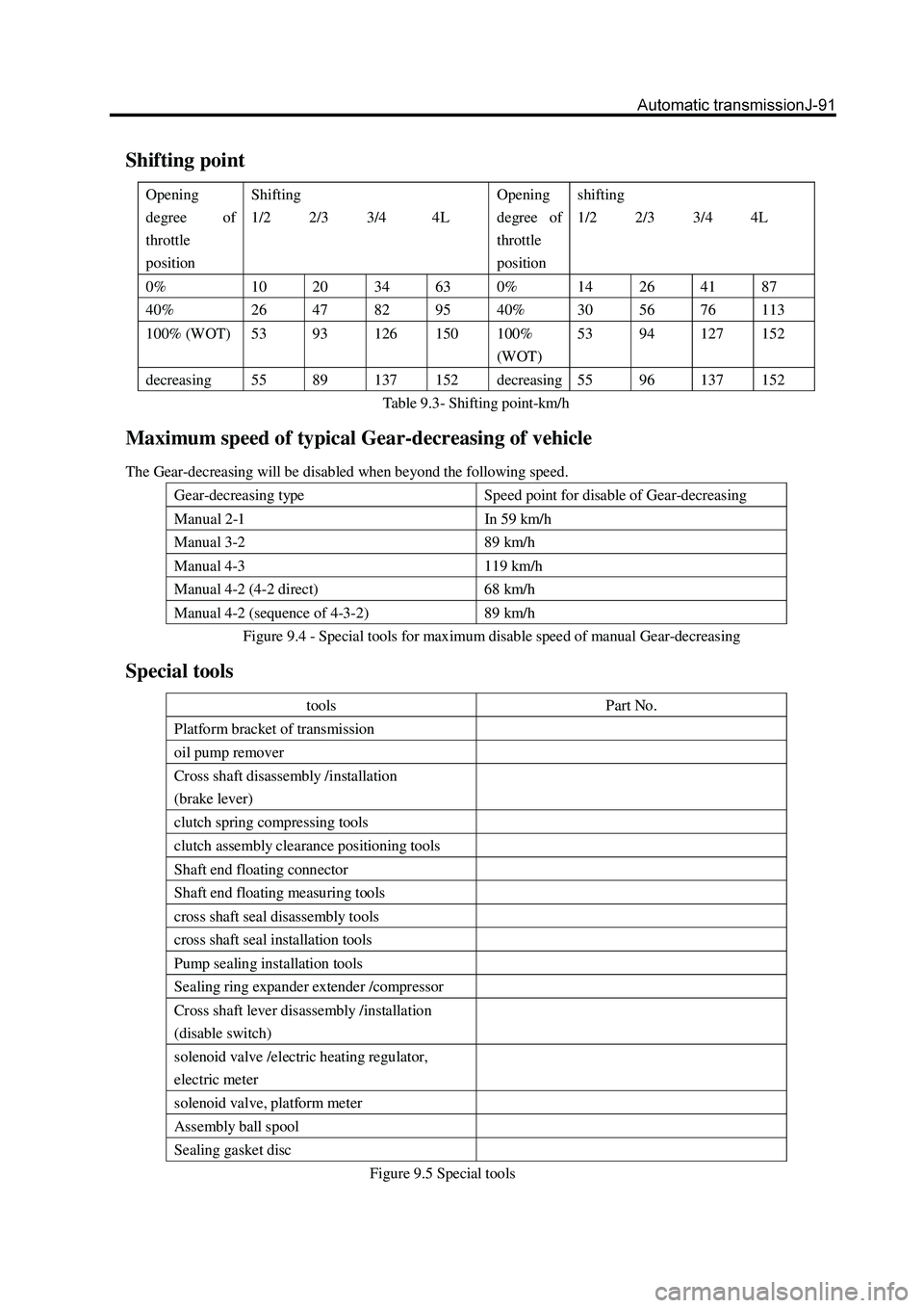
Shifting point
Opening
degree of
throttle
position Shifting
1/2 2/3 3/4 4L Opening
degree of
throttle
position shifting
1/2 2/3 3/4 4L
0% 10 20 34 63 0% 14 26 41 87
40% 26 47 82 95 40% 30 56 76 113
100% (WOT) 53 93 126 150 100%
(WOT) 53
94 127 152
decreasing 55 89 137 152 decreasing 55 96 137 152
Table 9.3- Shifting point-km/h
Maximum speed of typical Gear-decreasing of vehicle
The Gear-decreasing will be disabled when beyond the following speed.
Gear-decreasing type Speed point for disable of Gear-decreasing
Manual 2-1 In 59 km/h
Manual 3-2 89 km/h
Manual 4-3 119 km/h
Manual 4-2 (4-2 direct) 68 km/h
Manual 4-2 (sequence of 4-3-2) 89 km/h
Figure 9.4 - Special tools for maximum disable speed of manual Gear-decreasing
Special tools
tools Part No.
Platform bracket of transmission
oil pump remover
Cross shaft disassembly /installation
(brake lever)
clutch spring compressing tools
clutch assembly clearance positioning tools
Shaft end floating connector
Shaft end floating measuring tools
cross shaft seal disassembly tools
cross shaft seal installation tools
Pump sealing installation tools
Sealing ring expander extender /compressor
Cross shaft lever disassembly /installation
(disable switch)
solenoid valve /electric heating regulator,
electric meter
solenoid valve, platform meter
Assembly ball spool
Sealing gasket disc
Figure 9.5 Special tools
Page 308 of 425

Brake-22
2. Install the piston gasket in the tong body.
a. Screw the bleed screw into the bleed hole;
b. Install the square gasket in the sealing groove of two cylinders of
pump respectively after coat its working surface with proper
rubber lubricant.
Tightening torque 7
10Nm.
3. Connect the brake pipeline
Connect the brake oil pipe to the tong.
Tightening force: 50
5Nm
4. Fill up the brake system with the brake fluid and drain the air
in the brake system.
5. Check for leakage of brake fluid.
Rear parking brake
pull-out piece
spring draw bar
hand brake
stay wire
front brake shoe
lower tension spring
clearance-adjusting bolt
clearance-adjusting gear
clearance-adjusting
bolt head
pull-out piece
spring seat
pulling arm pin
rear brake shoe
brake shoe pulling arm
saddle type washer
push pedal
push pedal
release spring
stopper
upper release spring
rear brake disc
Used component which can not be used any more.
Removal of rear brake
Remarks: When the brake torque of the hand brake cannot meet
the brake requirement, the thickness of the brake shoe gasket
shall be tested. If it is less than the minimum value of brake show
gasket, the brake shoe shall be replaced.
minimum thickness: 1.0mm