2006 GREAT WALL HOVER differential
[x] Cancel search: differentialPage 15 of 425
Front shaft/axle
CC6460K wagon has the two-cross arm, independent suspension, breakaway front axle.
CC6460KY wagon has the two-cross arm, independent suspension, breakaway steering drive axle , hyperbolic gear single-stage main
reducer, plain bevel gear differential mechanism, universal drive semiaxle, Birfield ball-joint, main reduction ratio i
0=4.55, Max. input
torque is 900N
m.
Rear axle
Non-breakaway drive axle, integral stamping-welded axle housing, hyperbolic gear single-stage main reducer, plain bevel gear differential
mechanism, semi-floating semiaxle, main reduction ratio i
0=4.55, Max. input torque is 900Nm.
Wheel and tyre
The type, specification and main parameter of wheel and tyre see Table 4.
Table 4 Type, specification and main parameter of wheel and tyre
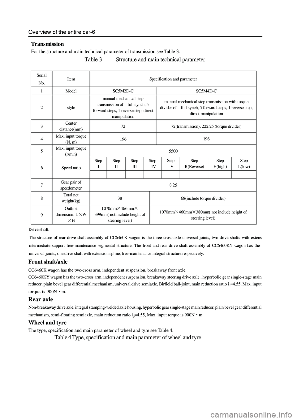
Transmission
For the structure and main technical parameter of transmission see Table 3.
Table 3 Structure and main technical parameter
Serial
No. Item Specification and parameter
1 Model SC5M2D-C SC5M4D-C
2 style manual mechanical step
transmission of full synch, 5
forward steps, 1 revers e step, direct
manipulation manual mechanical step transmission with torque
divider of full synch, 5 forward steps, 1 reverse step,
direct manipulation
3 Cent er
distance(mm) 72 72(transmission), 222.25 (torque divider)
4 Max. input torque
(N. m) 196 196
5 Max. input torque
(r/min) 5500
Step
I Step
II Step
III St ep
IV Step
V Step
R(Reverse) Step
H(high) St ep
L(low)
6 Speed ratio
7 Gear pair of
speedometer 8:25
8 To t a l n et
weight(kg) 38 68(include torque divider)
9 Outline
dimension: L×W
×H 1070mm×466mm×
399mm( not include height of
steering level) 1070mm×460mm×380mm( not include height of
steering level)
Drive shaft
The structure of rear drive shaft assembly of CC6460K wagon is the three cross-axle universal joints, two drive shafts with exten
s
intermediat e support free-maint enance segmental structure. The front and rear dr ive shaft assembly of CC6 460KY wa gon has the
universal joints, one drive shaft with extension spline, free-maintenance integral structure respectively.
Page 174 of 425
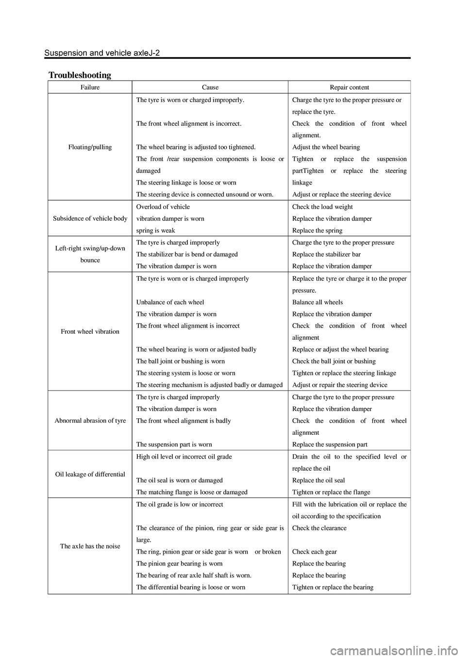
Troubleshooting
Failure Cause Repair cont ent
Floating/pulling The t yre is worn or charged improperly.
The front wheel alignment is incorrect.
The wheel bearing is adjusted too tightened.
The front /rear suspension components is loose or
damaged
The steering linkage is loose or worn
The steering device is connect ed unsound or worn. Charge the t yre to the prop er pressur e or
repla ce the t yre.
Check the condition of front wheel
alignment.
Adjust the wheel bearing
Tighten or replace the suspension
partTighten or replace the steering
linkage
Adjust or replace the steering device
Subsidence of vehicle body Overload of vehicle
vibration damper is worn
spring is weak Check the load weight
Replace the vibration damper
Replace the spring
Left-right swing/up-down
bounce The t yre is charged improperly
The stabilizer bar is bend or damaged
The vibration damper is worn Charge the t yre to the prop er pressur e
Replace the stabilizer bar
Replace the vibration damper
Front wheel vibration The t yre is worn or is charged improperly
Unbalance of each wheel
The vibration damper is worn
The front wheel alignment is incorrect
The wheel bearing is worn or adjusted badly
The ball joint or bushing is worn
The steering system is loose or worn
The steering mechanism is adjusted badly or damaged Repla ce the t yr e or char ge it to the prop er
pressure.
Balance all wheels
Replace the vibration damper
Check the condition of front wheel
alignment
Replace or adjust the wheel bearing
Check the ball joint or bushing
Tighten or replace the steering linkage
Adjust or repair the steering device
Abnormal abrasion of tyre The t yre is charged improperly
The vibration damper is worn
The front wheel alignment is badly
The suspension part is worn Charge the t yre to the prop er pressur e
Replace the vibration damper
Check the condition of front wheel
alignment
Replace the suspension part
Oil leakage of differential High oil level or incorrect oil grade
The oil seal is worn or damaged
The matching flange is loose or damaged Drain the oil to the specified level or
repla ce the oil
Replace the oil seal
Tighten or replace the flange
The axle has the nois e The oil grade is low or incorrect
The clearance of the pinion, ring gear or side gear is
large.
The ring, pinion gear or side gear is worn or broken
The pinion gear bearing is worn
The b earing of rear axle half shaft is worn.
The differential b earing is loos e or worn Fill with the lubrication oil or replace the
oil according to the specification
Check the clearance
Check each gear
Replace the bearing
Replace the bearing
Tighten or replace the bearing
Page 233 of 425
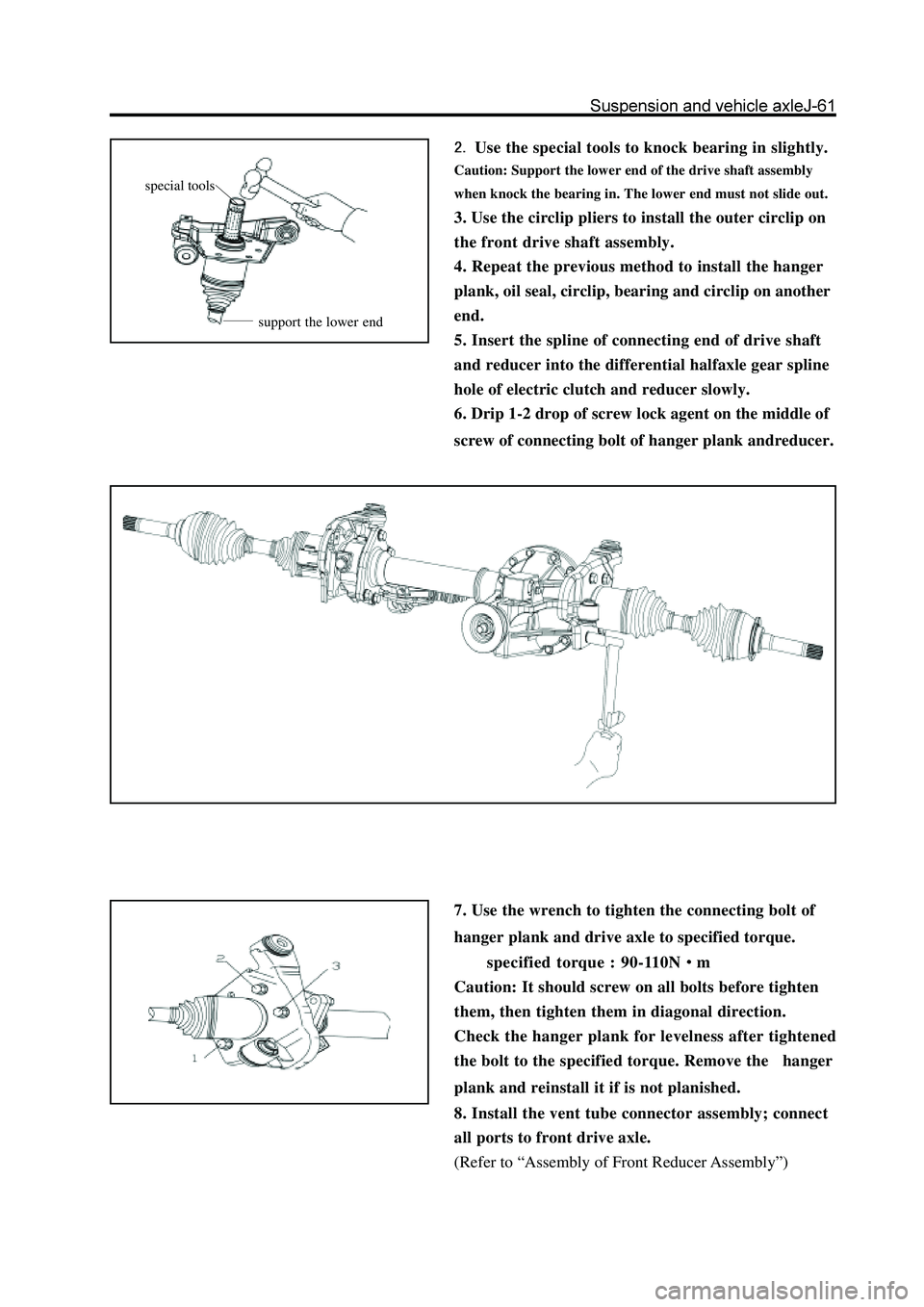
Use the special tools to knock bearing in slightly.
Caution: Support the lower end of the drive shaft assembly
when knock the bearing in. The lower end must not slide out.
3. Use the circlip pliers to install the outer circlip on
the front drive shaft assembly.
4. Repeat the previous method to install the hanger
plank, oil seal, circlip, bearing and circlip on another
end.
5. Insert the spline of connecting end of drive shaft
and reducer into the differential halfaxle gear spline
hole of electric clutch and reducer slowly.
6. Drip 1-2 drop of screw lock agent on the middle of
screw of connecting bolt of hanger plank andreducer.
7. Use the wrench to tighten the connecting bolt of
hanger plank and drive axle to specified torque.
specified torque : 90-110N
m
Caution: It should screw on all bolts before tighten
them, then tighten them in diagonal direction.
Check the hanger plank for levelness after tightened
the bolt to the specified torque. Remove the hanger
plank and reinstall it if is not planished.
8. Install the vent tube connector assembly; connect
all ports to front drive axle.
(Refer to “Assembly of Front Reducer Assembly”)
special tools
support the lower end
Page 235 of 425

Replacement of drive gear oil seal of front reducer assembly
1. Support the front of car; remove the left and right
front wheel and the beam under the reducer.
2. Drain the lubricant oil in the front reducer; remove
the left and right steering knuckle
3. Disconnect the front reducer assembly flange from
the drive shaft and use the jack to remove the front
drive axle
Caution: Make the assembly mark on the reducer and
drive shaft before separate them.
4. Remove the front differential assembly
(Caution: Drain the oil in front differential before the
disassembly)
front reducer
assembly
washer
spacer drive
bevel gear
bearing
oil seal
front reducer drive gear flange,
main gear flange and dustproof
cover assembly
Used component which can not be used
any more.
N m: specified torque
assembly mark
Page 248 of 425

Disassembly and assembly of front reducer assembly and electric clutch
adjusting shim
bearing gland
differential housing
driven bevel gear
front drive axle housing
washer
oil filling plug
vent tube
clip
front axle vents tube
connector assembly
major semiaxle
needle bearingelectric clutch
location pin
vent tube
mechanical wheel of separator
declutch shift sleeve
electric clutch housing
oil filling plug
circlip
major semiaxle oil seal
half axle gear thrust plate
half axle gear
planetary gear shaft
planetary gear
bolt clump
weight bracketclump weight and bush
assembly
clump weight bracket
welded assembly
front reducer
housing
adjusting washerspacer
drive bevel gear
small bearingoil sealfront drive gear flange and
dustproof cover assembly
drive bevel gearadjusting washer
Pregummed component
N m: Specified torque
Used component which
can not be used any more.bearing
circlip
big bearing
Page 253 of 425

25. Use the special tools to remove the small
bearing inner race, and then reverse the reducer
to slide out the spacer.
Remarks: The bearing should be replaced by new
one if damaged.
26. Use the wrench to remove two bearing glands.
Remarks: It should distinguish the left and right of
the bearing gland when remove it to avoid the
confusion.
Remove the side bearing outer race and marked
with L and R.
29. Remove the left and right adjusting washer; mea-
sure its thickness; marked with left and right. 27. Use the brass rod to vibrate the differential
assembly upwardly, then take out the differential
assembly.
holding
pliers
special tools
rotate the wrench in clockwise
24. Use the special tools to remove the drive gear oil
seal.
Page 255 of 425
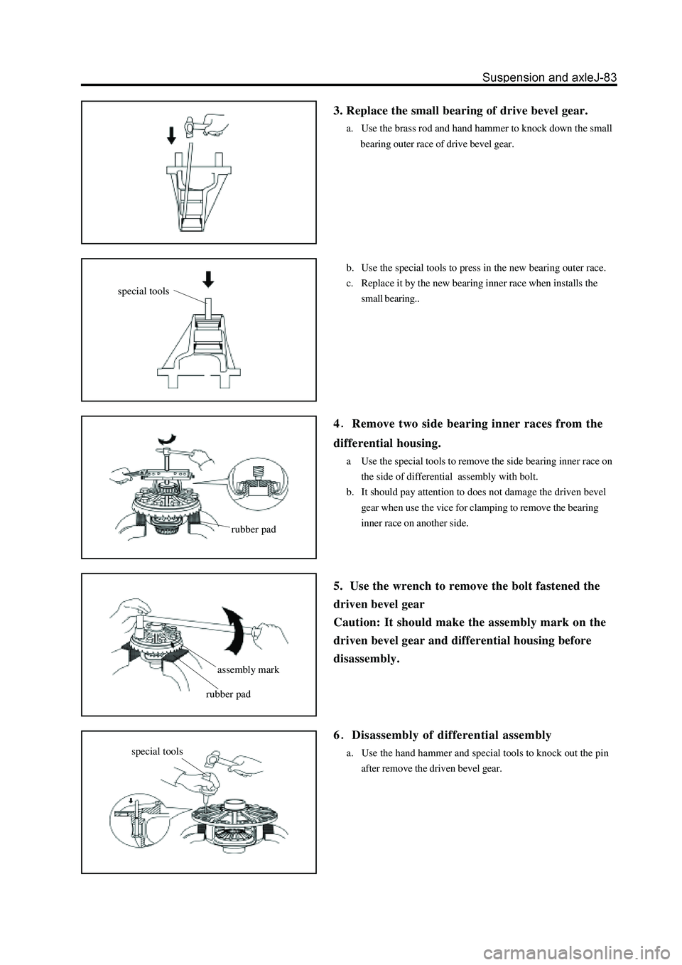
3. Replace the small bearing of drive bevel gear.
a. Use the brass rod and hand hammer to knock down the small
bearing outer race of drive bevel gear.
b. Use the special tools to press in the new bearing outer race.
c. Replace it by the new bearing inner race when installs the
small bearing..
4Remove two side bearing inner races from the
differential housing.
a Use the special tools to remove the side bearing inner race on
the side of differential assembly with bolt.
b. It should pay attention to does not damage the driven bevel
gear when use the vice for clamping to remove the bearing
inner race on another side.
5. Use the wrench to remove the bolt fastened the
driven bevel gear
Caution: It should make the assembly mark on the
driven bevel gear and differential housing before
disassembly.
6
Disassembly of differential assembly
a. Use the hand hammer and special tools to knock out the pin
after remove the driven bevel gear.
special tools
rubber pad
assembly mark
rubber pad
special tools
Page 256 of 425
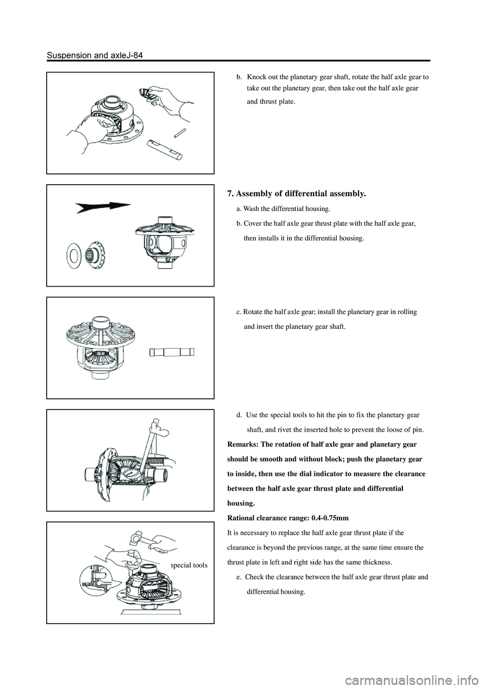
b. Knock out the planetary gear shaft, rotate the half axle gear to
take out the planetary gear, then take out the half axle gear
and thrust plate.
7. Assembly of differential assembly.
a. Wash the differential housing.
b. Cover the half axle gear thrust plate with the half axle gear,
then installs it in the differential housing.
c. Rotate the half axle gear; install the planetary gear in rolling
and insert the planetary gear shaft.
d. Use the special tools to hit the pin to fix the planetary gear
shaft, and rivet the inserted hole to prevent the loose of pin.
Remarks: The rotation of half axle gear and planetary gear
should be smooth and without block; push the planetary gear
to inside, then use the dial indicator to measure the clearance
between the half axle gear thrust plate and differential
housing.
Rational clearance range: 0.4-0.75mm
It is necessary to replace the half axle gear thrust plate if the
clearance is beyond the previous range, at the same time ensure the
thrust plate in left and right side has the same thickness.
e. Check the clearance between the half axle gear thrust plate and
differential housing.
special tools