Page 257 of 425

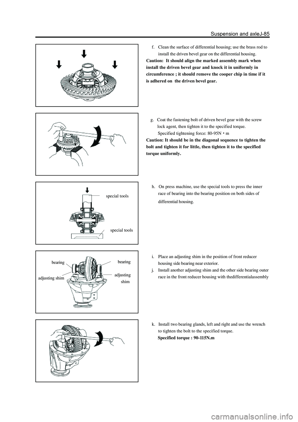
f. Clean the surface of differential housing; use the brass rod to
install the driven bevel gear on the differential housing.
Caution: It should align the marked assembly mark when
install the driven bevel gear and knock it in uniformly in
circumference ; it should remove the cooper chip in time if it
is adhered on the driven bevel gear.
g. Coat the fastening bolt of driven bevel gear with the screw
lock agent, then tighten it to the specified torque.
Specified tightening force: 80-95N
m
Caution: It should be in the diagonal sequence to tighten the
bolt and tighten it for little, then tighten it to the specified
torque uniformly.
h. On press machine, use the special tools to press the inner
race of bearing into the bearing position on both sides of
differential housing.
i. Place an adjusting shim in the position of front reducer
housing side bearing near exterior.
j. Install another adjusting shim and the other side bearing outer
race in the front reducer housing with thedifferentialassembly
k. Install two bearing glands, left and right and use the wrench
to tighten the bolt to the specified torque.
Specified torque : 90-115N.m
special tools
special tools
bearingbearing
adjusting shimadjusting
shim
Page 259 of 425
8. Place the differential assembly on the corresponding
position of front reducer housing.
9.Select an adjusting shim and insert it in a side of
side bearing outer race; push the differential assem-
bly to the side with adjusting shim.
10. Use the dial indicator to measure the gear side
clearance of driven bevel gear and drive bevel gear;
select out the adjusting shim in the side which meets
the rational clearance of 0.15mm.
11.Measure the thickness of the adjusting shim.
12. After select out one side adjusting shim, then
select theadjusting of another side according to that
the theoreticthickness of the adjusting shimofanother
side equals to subtracting the thickness of selected
shim and oppositiondistance L2 between outer race of
two side bearings of differential assembly from the
opposition distance L1 between two side bearings of
front reducer housing.
Page 260 of 425

13. Place an adjusting shim in the position of front
reducer housing side bearing and close to exterior.
14. Install the other adjusting shim and the bearing
outer race of another side with the differential
assembly into the front reducer housing.
Remarks: Ensure the selected adjusting shim has
not gap with front reducer housing.
15. Rotate the driven bevel gear to make the differ-
ential assembly closed to the front reducer housing.
16. Use the dial indicator to measure the tooth side
gap between the drive and driven bevel gear.
The rational range of gap is: 0.15-0.25mm.
If the measured gap is beyond the range, then adjust it by
adding or reducing the thickness of shim. ( When add in
one side, the other side should be reduced with same
thickness)
Caution: Ensure the selected adjusting shim is
without clearance form front reducer housing.
17. Adjust the pre-applled axial load of side bearing.
a. Remove two adjusting shim, remeasure the thickness of two
adjusting shims.
b. Install the new adjusting shim with thickness 0.06-0.09mm
more than that of removed adjusting shim, then install it with
the differential in the reducer housing.
c. Remeasure the tooth side clearance between the drive bevel
gear and driven bevel gear.
Rational range of clearance: 0.15-0.25mm
Remarks: If the measured gap is beyond the range, then adjust
it by adding or reducing the thickness of shim. ( When add in
one side, the other side should be reduced with same
thickness)
Caution: Ensure the selected adjusting shim has not the
clearance with the front reducer housing.
18. Install the bearing gland of both sides and use
the wrench to tighten it to the specified torque.
specified torque : 90-115Nm
Remarks: Distinguish the left and right during assembly.
Page 271 of 425
Reducer
Replace the oil seal on the car
1. Disconnect the reducer from the drive shaft.
a. Make the assembly mark on two flanges.
b. Remove four bolts and nuts.
2. Remove the flange and dustproof cover assembly
3. Remove the oil seal
Use the special tools to remove the oil seal.
bearing spacer
adjusting washer
rear bearing
drive bevel gear
adjusting ring
side bearingdriven bevel gear
differential housing
locking plate
plain washer
flange
dustproof cover
oil seal
oil baffle disc
front bearingbearing glandstop plate
lock washer with
double ears
N m: Specified torque
Used component which can not be used any more.
assembly mark
Page 273 of 425

Disassembly of reducer
Remarks: If the noise of differential is loud, process the follow-
ing inspection before disassembles the differential to determine
its reason. When the differential has serious problems, it can be
disassembled for repair if necessary.
1. Check the internal clearance of driven bevel gear.
If the clearance is beyond the specified range; adjust the preapplied
load of bearing or repair if necessary.
(Refer to step 13 “Assembly of Reducer”)
Standard internal clearance: 0.15-0.25mm
2. Check the intertooth contact of drive bevel gear
and driven bevel gear.
(Refer to Step 14 in “Assembly of Reducer”)
Record the contact position of tooth.
3. Check the clearance between the thrust plate of
axle shaft gear and differential housing.
Use the feeler to measure the clearance between the thrust plate
of axle shaft gear and differential housing.
Standard clearance: 0.45-0.75mm
It should be replaced by the proper thrust washer if the clearance
is beyond the specified range.
(Refer to Step 2 in “Replacement of Differential Components”)
4. Measure the pre-applied load of drive bevel gear
Use the torsion meter to measure the pre-applied load on the
internal clearance between the drive small gear and driven bevel
gear.
Pre-applied load: 0.4-0.6N
m
5. Total pre-applied load
Use the torsion meter to measure the total pre-applied load.
Pre-applied load : 0.9-1.3N
m
6. Remove the differential and driven bevel gear
a. Make the assembly mark on the differential bearing gland and
reducer housing.
b.Remove two stop plates.
c.Remove two bearing glands and two adjusting rings.
d.Remove the bearing outer race.
e.Remove the differential form the reducer housing.
Page 275 of 425
b.Use the press machine and special tools to install the reused
adjusting washer and new rear bearing on the drive bevel gear.
12. Replacement of front and rear bearing outer race
of drive bevel gear.
a. Use the hammer and brass bar to knock out the front and rear
bearing.
b. Use the press machine and special tools to install the new
bearing outer race by press.
13. Remove the side bearing form the differential
housing.
Use the special tools to pull out the side bearing from the differ
ential housing.
14. Remove the driven bevel gear
a.Remove the connecting bolt and lock plate of driven bevel gear.
b.Make the assembly mark on the driven bevel gear and differen
tial housing.
c.Use the rubber hammer or brass rod to knock down the driven
bevel gear.
Assembly of reducer
1. Install the bearing outer race of drive bevel gear.
(Refer to Step 12 in “Disassembly of Reducer”)
special tools
Page 277 of 425

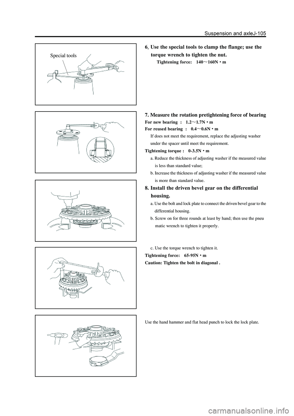
6Use the special tools to clamp the flange; use the
torque wrench to tighten the nut.
Tightening force: 140160Nm
7. Measure the rotation pretightening force of bearing
For new bearing : 1.21.7Nm
For reused bearing : 0.4
0.6Nm
If does not meet the requirement, replace the adjusting washer
under the spacer until meet the requirement.
Tightening torque : 0-3.5N
m
a. Reduce the thickness of adjusting washer if the measured value
is less than standard value;
b. Increase the thickness of adjusting washer if the measured value
is more than standard value.
8. Install the driven bevel gear on the differential
housing.
a. Use the bolt and lock plate to connect the driven bevel gear to the
differential housing.
b. Screw on for three rounds at least by hand; then use the pneu
matic wrench to tighten it properly.
c. Use the torque wrench to tighten it.
Tightening force: 65-95N
m
Caution: Tighten the bolt in diagonal .
Use the hand hammer and flat head punch to lock the lock plate.
Special tools
Page 278 of 425

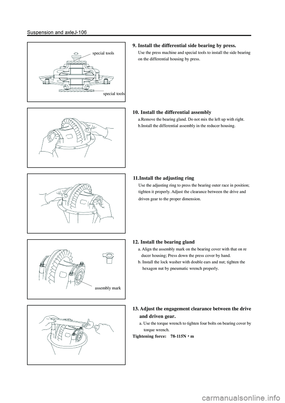
9. Install the differential side bearing by press.
Use the press machine and special tools to install the side bearing
on the differential housing by press.
10. Install the differential assembly
a.Remove the bearing gland. Do not mix the left up with right.
b.Install the differential assembly in the reducer housing.
11.Install the adjusting ring
Use the adjusting ring to press the bearing outer race in position;
tighten it properly. Adjust the clearance between the drive and
driven gear to the proper dimension.
12. Install the bearing gland
a. Align the assembly mark on the bearing cover with that on re
ducer housing; Press down the press cover by hand.
b. Install the lock washer with double ears and nut; tighten the
hexagon nut by pneumatic wrench properly.
13. Adjust the engagement clearance between the drive
and driven gear.
a. Use the torque wrench to tighten four bolts on bearing cover by
torque wrench.
Tightening force: 78-115N
m
special tools
special tools
assembly mark