2006 GREAT WALL HOVER transmission
[x] Cancel search: transmissionPage 2 of 425

Preface
Since the Great Wall Hover is put into the market, it has won the favor from the customers for its
elegant appearance, excellent performance&price ratio,concept of double area and eternal safety.The car is
furnished with Mitsubishi 4G64 engine.It has both the type of five shifts manual transmission and the type of
automatic transmission as an option. At the same time, there are also options of ABS and safety airbag, etc.
Before of its complex structure, high technical intervention and difficulty of maintenance, its maintenance
needs the reference of related documents. Upon the request of the after-sale maintenance technical personnel
of Great Wall, we have prepared this Hover Maintenance Manual. The manual is oriented towards the after-
sale maintenance technical personnel of the Great Wall, and mainly introduces the disassembly of the various
systems of Hover (refer to the maintenance manual of motor for the introduction of the motor), the
troubleshooting, matters needing attention for maintenance and the related technical parameters.
During the preparation of this book, a lot of professional personnel have given support and help, here we
would like to express our sincere thanks.
Though we have made efforts to prepare this manual earnestly, we cannot guarantee that the content in
the manual is totally accurate and without error. The user cannot raise improper request to the Great Wall
Company with the manual as legal basis. We cannot bear any responsibility for the losses caused by using
this manual. Confined to the knowledge of the editor, the fault and errors are inevitable, your advice and
comment are appreciated.
The final authority for the interpretation of this manual belongs to the Great Wall Motor Co., Ltd.
Page 9 of 425

Preface
Table of Contents
Instruction How to use the manual
Chapter 1 Overview of the entire car (parameters)
Chapter 2 Fuel supply system and exhaust air system
Chapter 3 Clutch
Chapter 4 Transmission
Chapter 5 Automatic transmission
Chapter 6 Driving shaft
Chapter 7 Suspension and vehicle axle
Chapter 8 Brake (ABS)
Chapter 9 Steering
Chapter 10 Car body electric appliance
Chapter 11 CD player and air-conditioning system
Chapter 12 Safety airbag
Annex:
Important components guarantee and requirement
List of non-metal material consumption
Special tools
D Important working components and tightening torque
E Electric wiring diagram
Page 10 of 425

Overview of the entire car-1
Chapter 1
Overview of the entire car
Basic parameter....................................................... 2
Engine..................................................................... 4
Air inlet system........................................................ 5
Exhaust air system................................................... 5
Fuel supply system................................................... 5
Cooling system........................................................ 5
Clutch..................................................................... 5
Transmission............................................................ 6
Drive shaft............................................................... 6
Front shaft/axle........................................................ 6
Rear axle................................................................. 6
Wheel tyre............................................................... 6
Suspension.............................................................. 7
Frame..................................................................... 7
Steering system........................................................ 7
Brake system........................................................... 8
Car body................................................................. 9
Electrical system.................................................... 10
Air-conditioning system …………………..............12
Page 15 of 425

Front shaft/axle
CC6460K wagon has the two-cross arm, independent suspension, breakaway front axle.
CC6460KY wagon has the two-cross arm, independent suspension, breakaway steering drive axle , hyperbolic gear single-stage main
reducer, plain bevel gear differential mechanism, universal drive semiaxle, Birfield ball-joint, main reduction ratio i
0=4.55, Max. input
torque is 900N
m.
Rear axle
Non-breakaway drive axle, integral stamping-welded axle housing, hyperbolic gear single-stage main reducer, plain bevel gear differential
mechanism, semi-floating semiaxle, main reduction ratio i
0=4.55, Max. input torque is 900Nm.
Wheel and tyre
The type, specification and main parameter of wheel and tyre see Table 4.
Table 4 Type, specification and main parameter of wheel and tyre
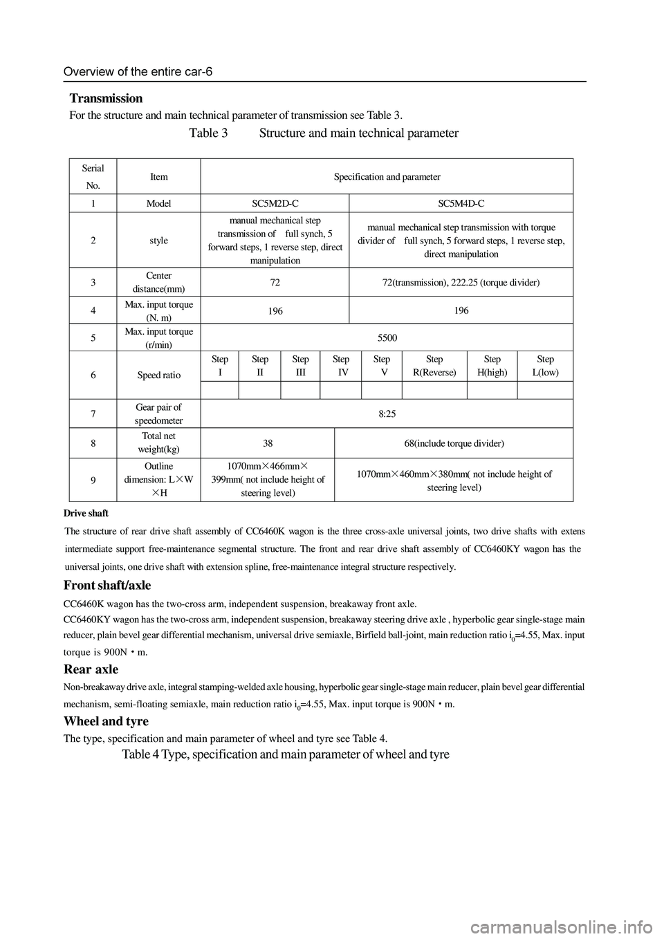
Transmission
For the structure and main technical parameter of transmission see Table 3.
Table 3 Structure and main technical parameter
Serial
No. Item Specification and parameter
1 Model SC5M2D-C SC5M4D-C
2 style manual mechanical step
transmission of full synch, 5
forward steps, 1 revers e step, direct
manipulation manual mechanical step transmission with torque
divider of full synch, 5 forward steps, 1 reverse step,
direct manipulation
3 Cent er
distance(mm) 72 72(transmission), 222.25 (torque divider)
4 Max. input torque
(N. m) 196 196
5 Max. input torque
(r/min) 5500
Step
I Step
II Step
III St ep
IV Step
V Step
R(Reverse) Step
H(high) St ep
L(low)
6 Speed ratio
7 Gear pair of
speedometer 8:25
8 To t a l n et
weight(kg) 38 68(include torque divider)
9 Outline
dimension: L×W
×H 1070mm×466mm×
399mm( not include height of
steering level) 1070mm×460mm×380mm( not include height of
steering level)
Drive shaft
The structure of rear drive shaft assembly of CC6460K wagon is the three cross-axle universal joints, two drive shafts with exten
s
intermediat e support free-maint enance segmental structure. The front and rear dr ive shaft assembly of CC6 460KY wa gon has the
universal joints, one drive shaft with extension spline, free-maintenance integral structure respectively.
Page 32 of 425

Clutch-2
Troubleshooting
failure cause inspection content
Shift difficulty or can not shift
Large free stroke of clut ch pedal clutch Pipe
has air
Failure of clutch cylinder
Failure of clutch master cylinder
The installation position of clutch disc is not
in position; large deviation; oil on the friction
lining or broken
The clutch disc is dirty or with foreign
material
Failure of clutch cover Adjust the free stroke of pedal
Discharge the air in clutch system
Replace
replace
Inspect the clutch disc; replace
Repair if necessary
Replace
Disengagement of transmission The clutch guide bearing is worn. Replace the guide bearing
Slide of clut ch
insufficient free stroke of clutch pedal
oil on the clutch disc friction lining or broken
failure of press disc
separation rocker arm assembly is blocked Adjust the free stroke of pedal
Inspect the clutch disc and replace it
Replace the clut ch cover
Check the separation rocker arm assembly
clutch clamping
stagnation/vibration oil on the clutch disc friction lining or broken
failure of press disc clutch membrane spring
is bend
loose of engine bracket Inspect the clutch disc and replace
Replace the clut ch cover
Correct the clutch membrane
Repair if necessary
Soft of clutch pedal clutch pip e has air
failure of clutch cylinder
failure of clutch master cylinder Discharge the air in clutch
replace
replace
Loud noise of clut ch
Component in clutch housing is loose
Throw-out bearing is worn or dirty
guide bearing is worn
separation rocker arm assembly or pull-rod is
blocked Repair if necessary
replace
replace
Repair if necessary
Page 36 of 425

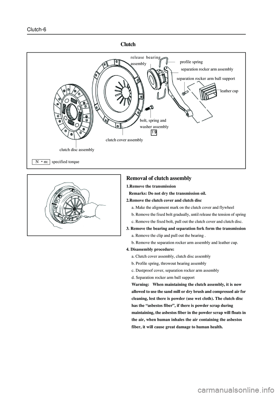
Clutch-6
Clutch
4. Disassembly procedure:
a. Clutch cover assembly, clutch disc assembly
b. Profile spring, throwout bearing assembly
c. Dustproof cover, separation rocker arm assembly
d. Separation rocker arm ball support
Warning: When maintaining the clutch assembly, it is now
allowed to use the sand mill or dry brush and compressed air for
cleaning, lest there is powder (use wet cloth). The clutch disc
has the “asbestos fiber”, if there is powder scrap during
maintaining, the asbestos fiber in the powder scrap will floats in
the air, when human inhales the air containing the asbestos
fiber, it will cause great damage to human health.
Removal of clutch assembly
1.Remove the transmission
Remarks: Do not dry the transmission oil.
2.Remove the clutch cover and clutch disc
a. Make the alignment mark on the clutch cover and flywheel
b. Remove the fixed bolt gradually, until release the tension of spring
c. Remove the fixed bolt, pull out the clutch cover and clutch disc.
3. Remove the bearing and separation fork form the transmission
a. Remove the clip and pull out the bearing .
b. Remove the separation rocker arm assembly and leather cup.
clutch disc assembly
clutch cover assembly
bolt, spring and
washer assembly release bearing
assembly
profile spring
separation rocker arm assembly
separation rocker arm ball support
leather cup
N m: specified torque
Page 39 of 425

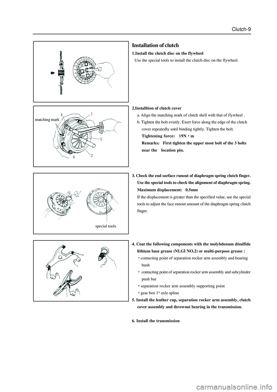
Clutch-9
2.Installtion of clutch cover
a. Align the matching mark of clutch shell with that of flywheel .
b. Tighten the bolt evenly. Exert force along the edge of the clutch
cover repeatedly until binding tightly. Tighten the bolt.
Tightening force: 19N
m
Remarks: First tighten the upper most bolt of the 3 bolts
near thelocation pin.
3. Check the end surface runout of diaphragm spring clutch finger.
Use the special tools to check the alignment of diaphragm spring.
Maximum displacement: 0.5mm
If the displacement is greater than the specified value, use the special
tools to adjust the face runout amount of the diaphragm spring clutch
finger.
4. Coat the following components with the molybdenum disulfide
lithium base grease (NLGI NO.2) or multi-purpose grease :
contacting point of separation rocker arm assembly and bearing
bush
contacting point of separation rocker arm assembly and subcylinder
push bar
separation rocker arm assembly supporting point
gear box 1st axle spline
5. Install the leather cup, separation rocker arm assembly, clutch
cover assembly and throwout bearing in the transmission.
6. Install the transmission
matching mark
Installation of clutch
1.Install the clutch disc on the flywheel
Use the special tools to install the clutch disc on the flywheel.
special tools
Page 40 of 425

Chapter 4
Specification of transmission.......................................................................2
Repair of transmission (SC5M2D
C).....................................................4
Disassembly of transmission (SC5M2D
C)............................................6
Disassembly of transmission housing assembly/bearing housing assembly....18
Operating instruction of transmission (SC5M4D
C).............................24
Repair of transmission (SC5M4D
C)...................................................25
Disassembly of rear housing assembly ......................................................28
Disassembly of transfer case assembly......................................................30
Rear output shaft assembly .......................................................................35