Page 286 of 425
Removal of connecting rod of stabilizer bar:
1.Shown as figure, firstly screw off the nut in the con
necting place between the connecting rod of stabi
lizer bar and carriage. (Need the inner hexagon
spanner ).
2.Screw off the nut connected to stabilizer bar in same
method; screw off the connecting rod.
Installation of connecting rod of stabilizer bar:
Tighten it to the specified torque during installation:
63
5Nm
Page 290 of 425

Brake-4
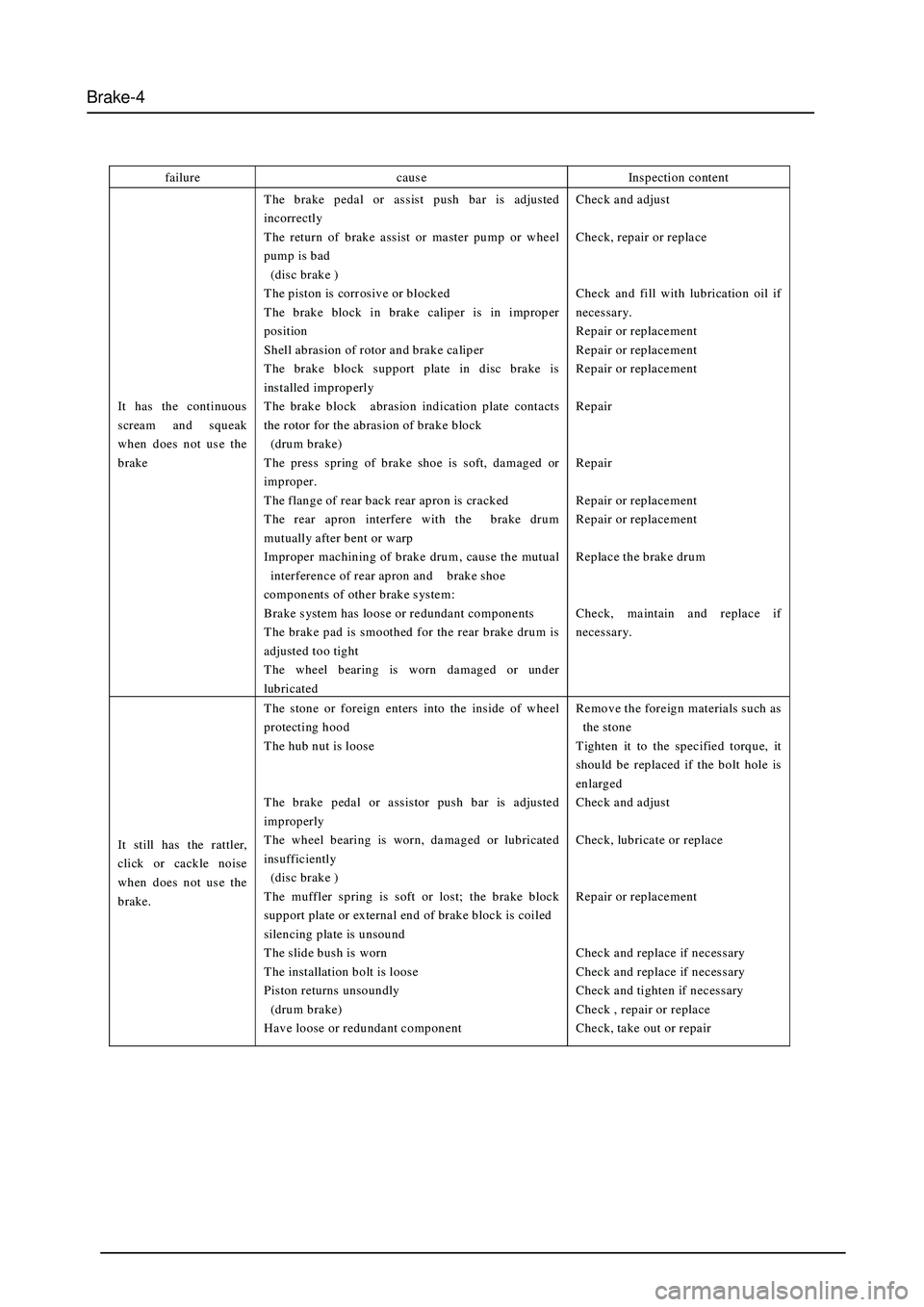
failure caus e Inspection content
It has the continuous
scream and squeak
when does not us e the
brake The brake pedal or assist push bar is adjusted
incorrectly
The return of brake assist or master pump or wheel
pump is bad
(dis c brake )
T he piston is corr osive or blocked
T he brake block in brake calip er is in improp er
position
Shell abrasion of rotor and brake caliper
The brake block support plate in disc brake is
installed improperly
The brake block abrasion indication plate contacts
the rotor for the abrasion of brake block
(drum brake)
The press spring of brake shoe is soft, damaged or
improper.
The flange of rear back rear apron is cracked
T he rear apron interfer e with the brake drum
mutually after bent or warp
Improper machining of brake drum , caus e the mutual
interference of rear apron and brake shoe
components of other brake s ystem :
Brake system has loose or redundant components
T he brake pad is smoothed for the rear brake drum is
adjusted too tight
The wheel bearing is worn damaged or under
lubricated Check and adjust
Check, repair or replace
Check and fill with lubrication oil if
necessary.
Repair or replacement
Repair or replacement
Repair or replacement
Repair
Repair
Repair or replacement
Repair or replacement
Replace the brake drum
Check, maintain and replace if
necessary.
It still has the rattler,
click or cackle noise
when does not us e the
brake. The stone or foreign enters into the inside of wheel
protecting hood
The hub nut is loose
The brake pedal or assistor push bar is adjusted
improperly
The wheel bearing is worn, damaged or lubricated
insufficiently
(dis c brake )
T he muffler spring is soft or lost; the brake block
support plate or external end of brake block is coiled
silencing plate is unsound
T he slide bush is worn
T he installation bolt is loos e
Piston returns unsoundly
(drum brake)
Have loose or redundant component Remove the foreign materials such as
the stone
Tighten it to the specified torque, it
should be replaced if the bolt hole is
enlarged
Check and adjust
Check, lubricate or replace
Repair or replacement
Check and replace if necessary
Check and replace if necessary
Check and tighten if necessary
Check , repair or replace
Check, take out or repair
Page 293 of 425

Brake-7
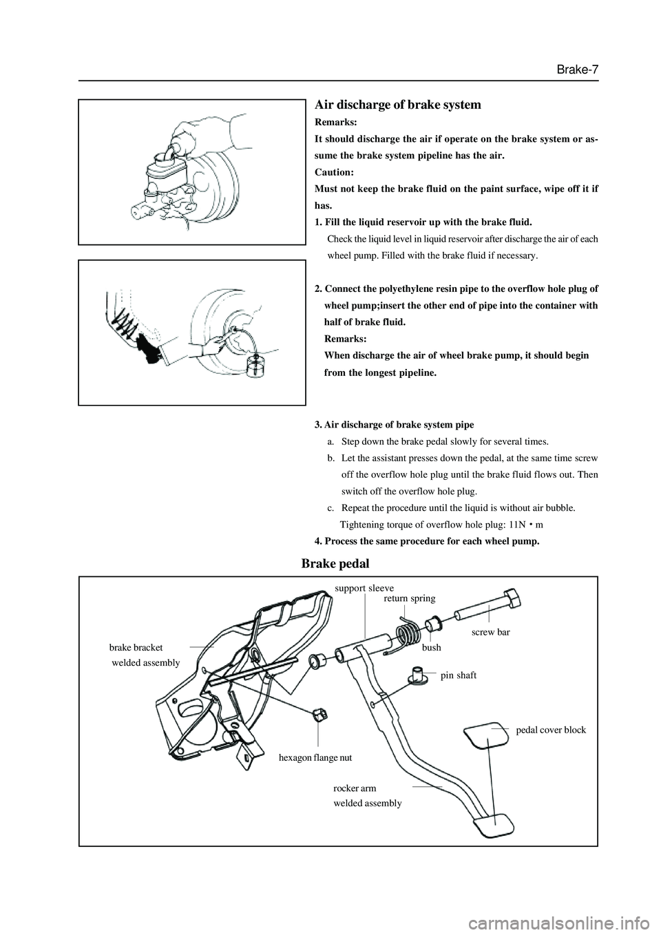
Air discharge of brake system
Remarks:
It should discharge the air if operate on the brake system or as-
sume the brake system pipeline has the air.
Caution:
Must not keep the brake fluid on the paint surface, wipe off it if
has.
1. Fill the liquid reservoir up with the brake fluid.
Check the liquid level in liquid reservoir after discharge the air of each
wheel pump. Filled with the brake fluid if necessary.
2. Connect the polyethylene resin pipe to the overflow hole plug of
wheel pump;insert the other end of pipe into the container with
half of brake fluid.
Remarks:
When discharge the air of wheel brake pump, it should begin
from the longest pipeline.
3. Air discharge of brake system pipe
a. Step down the brake pedal slowly for several times.
b. Let the assistant presses down the pedal, at the same time screw
off the overflow hole plug until the brake fluid flows out. Then
switch off the overflow hole plug.
c. Repeat the procedure until the liquid is without air bubble.
Tightening torque of overflow hole plug: 11N
m
4. Process the same procedure for each wheel pump.
hexagon flange nut
brake bracket
welded assembly
support sleevereturn spring
bush
screw bar
pin shaft
pedal cover block
rocker arm
welded assembly
Brake pedal
Page 294 of 425
Brake-8
Replacement of pin shaft
Remarks:
When the connecting fork pin shaft and pin hole is over worn, it
should replace the pin shaft bush.
Remarks:
When the clearance between the brake pedal shaft and bush is
large, it should remove the pedal and replace the bush.
push barlock nut
inner distance
fork pin shaft
Parking brake
parking crank assembly
switch assembly
rear parking brake pull wire (R)
rear parking brake pull wire (L)
brake pull wire clip
1. Adjust the parking crank assembly in position, 6
8 teeth.
2. When the parking brake pull wire is tightened, the torque should
be no more than 400N
m.
Page 295 of 425

Brake-9
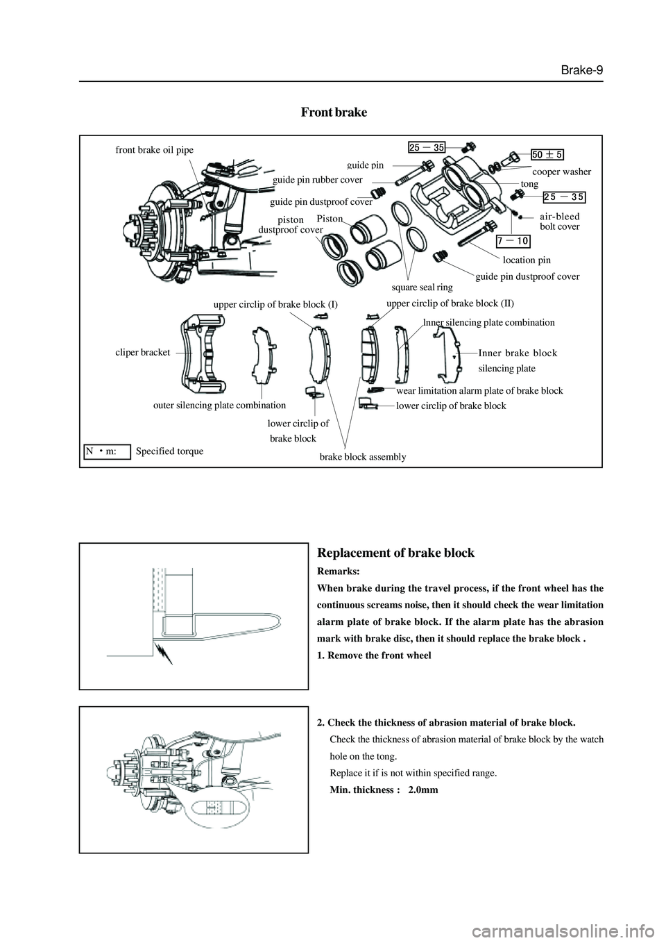
Front brake
front brake oil pipe
cliper bracket
outer silencing plate combination
lower circlip of
brake block
brake block assembly
lower circlip of brake block
wear limitation alarm plate of brake block
lnner silencing plate combination
Inner brake block
silencing plate
upper circlip of brake block (I)upper circlip of brake block (II)
piston
dustproof cover
guide pin dustproof cover
guide pin rubber covercooper washer
tong
air-bleed
bolt cover
location pin
guide pin dustproof coversquare seal ring
N
m: Specified torque
Piston
Replacement of brake block
Remarks:
When brake during the travel process, if the front wheel has the
continuous screams noise, then it should check the wear limitation
alarm plate of brake block. If the alarm plate has the abrasion
mark with brake disc, then it should replace the brake block .
1. Remove the front wheel
2. Check the thickness of abrasion material of brake block.
Check the thickness of abrasion material of brake block by the watch
hole on the tong.
Replace it if is not within specified range.
Min. thickness : 2.0mm
Page 299 of 425

Brake-13
Check the component of front brake
1. Measure the thickness of the brake block bush.
standard thickness: 9.0mm
minimum thickness: 2.0mm
It should replace the brake block if less than minimum thickness or
has uneven abrasion.
2. Measure the thickness of the brake disc.
standard thickness: 26.0mm
minimum thickness: 24.0mm
It should repair or replace the brake disc if the brake disc is damaged
or worn or its thickness is
less than minimum thickness.
3. Measure the circular runout of the brake disc.
Remarks: It should ensure that the bearing is adjusted correctly
before the measurement . maximum circular runout : 0.11mm
4. Replace the brake disc if necessary.
a. Remove the tong bracket form the steering knuckle.
b. Remove the hub and brake disc. (Refer to section “Front hub”)
c. Install the new brake disc; tighten the connecting bolt to the
specified torque.
Tightening force: 90
100Nm.
d. Install the hub and brake disassembly. (Refer to section “Front
hub”)
e. Install the tong bracket on the steering knuckle; tighten the
connecting bolt to the specified torque.
Tightening torque 140
10Nm.
Page 300 of 425

Brake-14
Assembly of brake pump
1. Preparation work
All components should be washed, dried by wind and without foreign
material before the assembly. During the assembly, cost the guide pin
and location pin with proper vacuum silicon based grease; coat the
working surface of piston and square gasket with proper rubber
lubricant.
2. Install the piston gasket in the tong body.
a. Screw the bleed screw into the bleed hole;
tightening torque 7
10Nm.
b. Install the square gasket in the sealing groove of two cylinders of
pump respectively after coat its working surface with proper
rubber lubricant.
3. Install the piston with dustproof cover in the tong
a. Cover the dustproof cover on the piston.
b. Lengthen the dustproof cover to expose the bottom of piston
from the dustproof cover clip ring; use the tool (for example: steel
wire about
2mm ) to assist insert the clip ring into the cylinder
hole clip ring groove.
Caution: The used tools must not be sharp to prevent the damage
of dustproof cover.
c. Press the piston to the bottom of cylinder hole by hand.
4. Pre Install the guide pin and location pin on the tong bracket.
a. Install the guide pin dustproof cover on the guide pin and location
pin respectively.
b. Screw the guide pin and location pin in the tong bracket
respectively.
Caution: Do not damage the guide pin dustproof cover.
Page 302 of 425

Brake-16
Rear brake (Disk-and-drum type)
tong bracket
pin rubber cover
brake caliper locking bolt 100
silencing plate
combination
outside brake block
inside brake block
brake block wearing
indication plate
cylinder hole
dustproof cover
wire clip
rectangle seal ring
piston
tong body (left)
copper washer
brake oil pipe fastening blot 55
location pin 2530
bleed screw
bleed screw dustproof cover
guide pin 2530
rear brake oil pipeline
N
m: specified torque
peepholesilencing
plate
Replacement of brake block
Remarks: if the rear wheel generates the cheep during the braking,
it should check the abrasion indication plate of brake block. If the
indication plate has the abrasion mark with brake disc, then it
should replace the brake block .
1. Remove the rear wheel
2. Check the thickness of brake block bush.
Measure the thickness of the brake block bush (abrasion material)
from the eyehole of tong. If the thickness is not within the specified
range, then it should replace the brake block.
minimum thickness: 2.0mm.