2006 DODGE RAM SRT-10 air condition
[x] Cancel search: air conditionPage 3458 of 5267
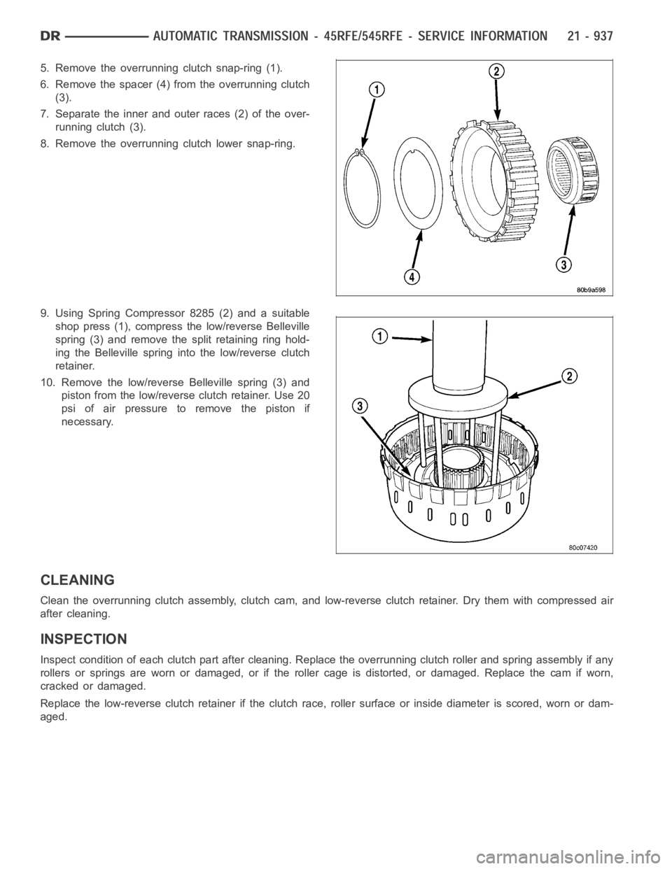
5. Remove the overrunning clutch snap-ring (1).
6. Remove the spacer (4) from the overrunning clutch
(3).
7. Separate the inner and outer races (2) of the over-
running clutch (3).
8. Remove the overrunning clutch lower snap-ring.
9. Using Spring Compressor 8285 (2) and a suitable
shop press (1), compress the low/reverse Belleville
spring (3) and remove the split retaining ring hold-
ing the Belleville spring into the low/reverse clutch
retainer.
10. Remove the low/reverse Belleville spring (3) and
piston from the low/reverse clutch retainer. Use 20
psi of air pressure to remove the piston if
necessary.
CLEANING
Cleantheoverrunningclutchassembly,clutchcam,andlow-reverseclutch retainer. Dry them with compressed air
after cleaning.
INSPECTION
Inspect condition of each clutch part after cleaning. Replace the overrunning clutch roller and spring assembly if any
rollers or springs are worn or damaged, or if the roller cage is distorted, or damaged. Replace the cam if worn,
cracked or damaged.
Replace the low-reverse clutch retainer if the clutch race, roller surface or inside diameter is scored, worn or dam-
aged.
Page 3478 of 5267
DISASSEMBLY
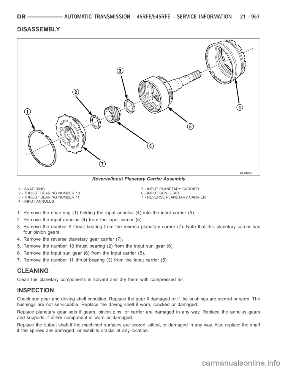
1. Remove the snap-ring (1) holding the input annulus (4) into the input carrier (5).
2. Remove the input annulus (4) from the input carrier (5).
3. Remove the number 9 thrust bearing from the reverse planetary carrier (7). Note that this planetary carrier has
four pinion gears.
4. Remove the reverse planetary gear carrier (7).
5. Remove the number 10 thrust bearing (2) from the input sun gear (6).
6. Remove the input sun gear (6) from the input carrier (5).
7. Remove the number 11 thrust bearing (3) from the input carrier (5).
CLEANING
Clean the planetary components in solvent and dry them with compressed air.
INSPECTION
Check sun gear and driving shell condition. Replace the gear if damaged or if the bushings are scored or worn. The
bushings are not serviceable. Replace the driving shell if worn, cracked or damaged.
Replace planetary gear sets if gears, pinion pins, or carrier are damaged in any way. Replace the annulus gears
and supports if either component is worn or damaged.
Replace the output shaft if the machined surfaces are scored, pitted, or damaged in any way. Also replace the shaft
if the splines are damaged, or exhibits cracks at any location.
Reverse/Input Planetary Carrier Assembly
1 - SNAP-RING 5 - INPUT PLANETARY CARRIER
2 - THRUST BEARING NUMBER 10 6 - INPUT SUN GEAR
3 - THRUST BEARING NUMBER 11 7 - REVERSE PLANETARY CARRIER
4 - INPUT ANNULUS
Page 3513 of 5267
Turn the ignition off to the lock position.
Remove the Transmission Oil Pan per the Service Information. (Refer to 21 -TRANSMISSION/TRANSAXLE/AU-
TOMATIC - 48RE/FLUID - STANDARD PROCEDURE)
Disconnect the Governor Pressure Sensor harness connector internal to the transmission.
NOTE: Check connectors - Clean/repair as necessary
Measure the resistance of the Transmission Temperature Sensor between the (T54) Transmission Temperature Sen-
sor Signal circuit and the (K900) Sensor Ground circuit.
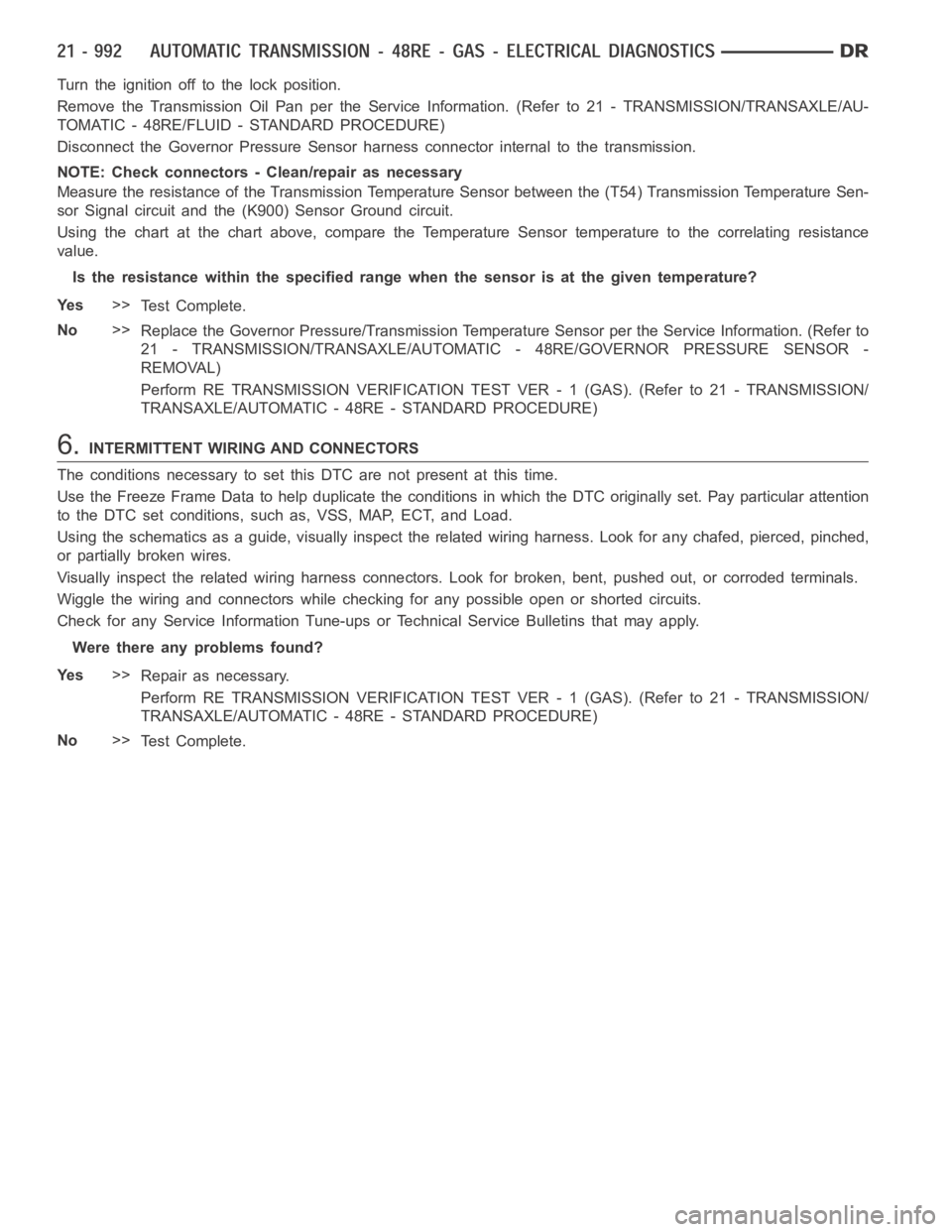
Using the chart at the chart above, compare the Temperature Sensor temperature to the correlating resistance
value.
Is the resistance within the specified range when the sensor is at the giventemperature?
Ye s>>
Te s t C o m p l e t e .
No>>
Replace the Governor Pressure/Transmission Temperature Sensor per the Service Information. (Refer to
21 - TRANSMISSION/TRANSAXLE/AUTOMATIC - 48RE/GOVERNOR PRESSURE SENSOR-
REMOVAL)
Perform RE TRANSMISSION VERIFICATION TEST VER - 1 (GAS). (Refer to 21 - TRANSMISSION/
TRANSAXLE/AUTOMATIC - 48RE - STANDARD PROCEDURE)
6.INTERMITTENT WIRING AND CONNECTORS
The conditions necessary to set this DTC are not present at this time.
Use the Freeze Frame Data to help duplicate the conditions in which the DTC originally set. Pay particular attention
to the DTC set conditions, such as, VSS, MAP, ECT, and Load.
Using the schematics as a guide, visually inspect the related wiring harness. Look for any chafed, pierced, pinched,
or partially broken wires.
Visually inspect the related wiring harness connectors. Look for broken,bent, pushed out, or corroded terminals.
Wiggle the wiring and connectors while checking for any possible open or shorted circuits.
Check for any Service Information Tune-ups or Technical Service Bulletins that may apply.
Were there any problems found?
Ye s>>
Repair as necessary.
Perform RE TRANSMISSION VERIFICATION TEST VER - 1 (GAS). (Refer to 21 - TRANSMISSION/
TRANSAXLE/AUTOMATIC - 48RE - STANDARD PROCEDURE)
No>>
Te s t C o m p l e t e .
Page 3519 of 5267
8 - ELECTRICAL/ELECTRONIC CONTROL MODULES/POWERTRAIN CONTROL MODULE -
REMOVAL)
Perform RE TRANSMISSION VERIFICATION TEST VER - 1 (GAS). (Refer to 21 - TRANSMISSION/
TRANSAXLE/AUTOMATIC - 48RE - STANDARD PROCEDURE)
8.INTERMITTENT WIRING AND CONNECTORS
The conditions necessary to set this DTC are not present at this time.
Use the Freeze Frame Data to help duplicate the conditions in which the DTC originally set. Pay particular attention
to the DTC set conditions, such as, VSS, MAP, ECT, and Load
Using the schematics as a guide, visually inspect the related wiring harness. Look for any chafed, pierced, pinched,
or partially broken wires.
Visually inspect the related wiring harness connectors. Look for broken,bent, pushed out, or corroded terminals.
Wiggle the wiring and connectors while checking for any possible open or shorted circuits.
Check for any Service Information Tune-ups or Technical Service Bulletins that may apply.
Were there any problems found?
Ye s>>
Repair as necessary.
Perform RE TRANSMISSION VERIFICATION TEST VER - 1 (GAS). (Refer to 21 - TRANSMISSION/
TRANSAXLE/AUTOMATIC - 48RE - STANDARD PROCEDURE)
No>>
Te s t C o m p l e t e .
Page 3527 of 5267
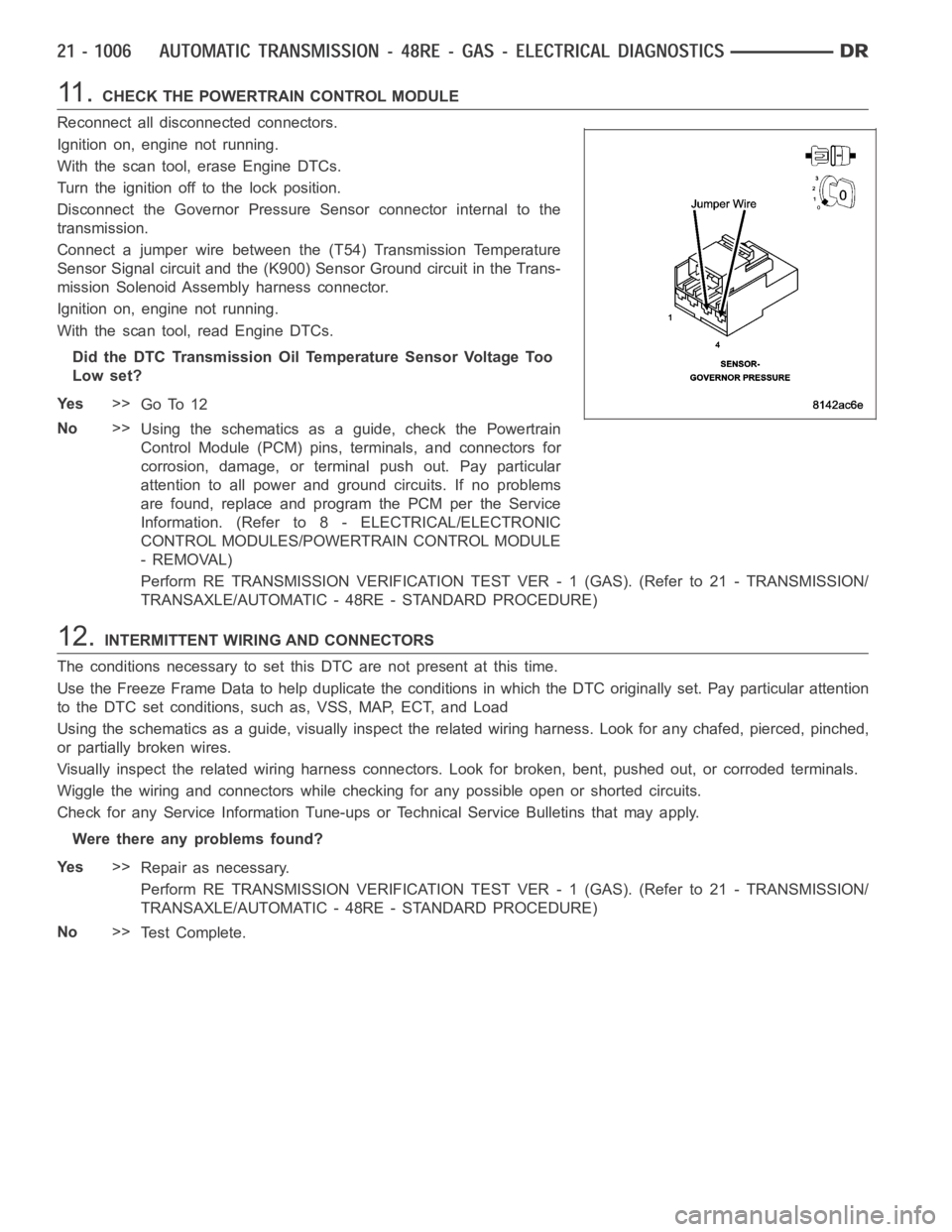
11 .CHECK THE POWERTRAIN CONTROL MODULE
Reconnect all disconnected connectors.
Ignition on, engine not running.
With the scan tool, erase Engine DTCs.
Turn the ignition off to the lock position.
Disconnect the Governor Pressure Sensor connector internal to the
transmission.
Connect a jumper wire between the (T54) Transmission Temperature
Sensor Signal circuit and the (K900) Sensor Ground circuit in the Trans-
mission Solenoid Assembly harness connector.
Ignition on, engine not running.
With the scan tool, read Engine DTCs.
Did the DTC Transmission Oil Temperature Sensor Voltage Too
Low set?
Ye s>>
Go To 12
No>>
Using the schematics as a guide, check the Powertrain
Control Module (PCM) pins, terminals, and connectors for
corrosion, damage, or terminal push out. Pay particular
attention to all power and ground circuits. If no problems
are found, replace and program the PCM per the Service
Information. (Refer to 8 - ELECTRICAL/ELECTRONIC
CONTROL MODULES/POWERTRAIN CONTROL MODULE
- REMOVAL)
Perform RE TRANSMISSION VERIFICATION TEST VER - 1 (GAS). (Refer to 21 - TRANSMISSION/
TRANSAXLE/AUTOMATIC - 48RE - STANDARD PROCEDURE)
12.INTERMITTENT WIRING AND CONNECTORS
The conditions necessary to set this DTC are not present at this time.
Use the Freeze Frame Data to help duplicate the conditions in which the DTC originally set. Pay particular attention
to the DTC set conditions, such as, VSS, MAP, ECT, and Load
Using the schematics as a guide, visually inspect the related wiring harness. Look for any chafed, pierced, pinched,
or partially broken wires.
Visually inspect the related wiring harness connectors. Look for broken,bent, pushed out, or corroded terminals.
Wiggle the wiring and connectors while checking for any possible open or shorted circuits.
Check for any Service Information Tune-ups or Technical Service Bulletins that may apply.
Were there any problems found?
Ye s>>
Repair as necessary.
Perform RE TRANSMISSION VERIFICATION TEST VER - 1 (GAS). (Refer to 21 - TRANSMISSION/
TRANSAXLE/AUTOMATIC - 48RE - STANDARD PROCEDURE)
No>>
Te s t C o m p l e t e .
Page 3533 of 5267
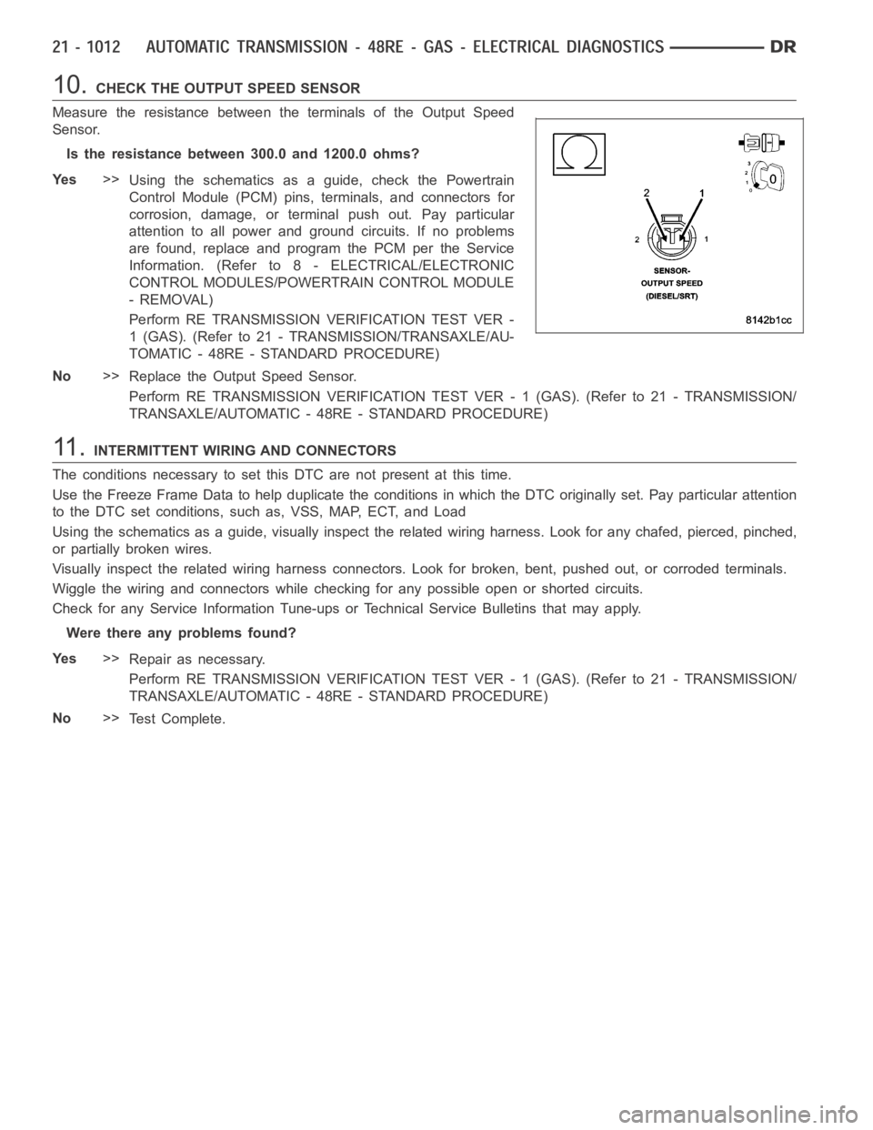
10.CHECK THE OUTPUT SPEED SENSOR
Measure the resistance between the terminals of the Output Speed
Sensor.
Is the resistance between 300.0 and 1200.0 ohms?
Ye s>>
Using the schematics as a guide, check the Powertrain
Control Module (PCM) pins, terminals, and connectors for
corrosion, damage, or terminal push out. Pay particular
attention to all power and ground circuits. If no problems
are found, replace and program the PCM per the Service
Information. (Refer to 8 - ELECTRICAL/ELECTRONIC
CONTROL MODULES/POWERTRAIN CONTROL MODULE
- REMOVAL)
Perform RE TRANSMISSION VERIFICATION TEST VER -
1 (GAS). (Refer to 21 - TRANSMISSION/TRANSAXLE/AU-
TOMATIC - 48RE - STANDARD PROCEDURE)
No>>
Replace the Output Speed Sensor.
Perform RE TRANSMISSION VERIFICATION TEST VER - 1 (GAS). (Refer to 21 - TRANSMISSION/
TRANSAXLE/AUTOMATIC - 48RE - STANDARD PROCEDURE)
11 .INTERMITTENT WIRING AND CONNECTORS
The conditions necessary to set this DTC are not present at this time.
Use the Freeze Frame Data to help duplicate the conditions in which the DTC originally set. Pay particular attention
to the DTC set conditions, such as, VSS, MAP, ECT, and Load
Using the schematics as a guide, visually inspect the related wiring harness. Look for any chafed, pierced, pinched,
or partially broken wires.
Visually inspect the related wiring harness connectors. Look for broken,bent, pushed out, or corroded terminals.
Wiggle the wiring and connectors while checking for any possible open or shorted circuits.
Check for any Service Information Tune-ups or Technical Service Bulletins that may apply.
Were there any problems found?
Ye s>>
Repair as necessary.
Perform RE TRANSMISSION VERIFICATION TEST VER - 1 (GAS). (Refer to 21 - TRANSMISSION/
TRANSAXLE/AUTOMATIC - 48RE - STANDARD PROCEDURE)
No>>
Te s t C o m p l e t e .
Page 3535 of 5267
Theory of Operation
The Torque Converter Clutch (TCC) solenoid is used to engage the TCC which improves fuel economy.
When Monitored:
Continuously with the ignition on.
Set Condition:
This DTC will set if the Torque Convertor Clutch (TCC) can not achieve the desired engine RPM drop when
the TCC Solenoid is near the maximum duty cycle after three consecutive test failures.
Possible Causes
TRANSMISSION FLUID LEVEL LOW OR CONTAMINATED
WORN OR DAMAGED REACTION SHAFT, INPUT SHAFT OR INPUT SHAFT SEALS
BLOCKED OR LEAK IN THE TCC HYDRAULIC CIRCUIT IN THE VALVE BODY
TORQUE CONVERTER CLUTCH SOLENOID
TORQUE CONVERTER
Always perform the Pre-Diagnostic Troubleshooting procedure before proceeding. (Refer to 21 - TRANSMIS-
SION/TRANSAXLE/AUTOMATIC - 48RE - STANDARD PROCEDURE)
1.CHECK IF THERE ANY ENGINE DTCS PRESENT
Ignition on, engine not running.
With the scan tool, read Engine DTCs.
Is the DTC P0743 also present?
Ye s>>
Refer to the Transmission category and perform the appropriate symptom(s). (Refer to 21 - TRANS-
MISSION/TRANSAXLE/AUTOMATIC - 48RE - DIAGNOSIS AND TESTING)
No>>
Go To 2
2.CHECK TRANSMISSION FLUID LEVEL
Check the transmission fluid level.
Is the Transmission fluid level low?
Ye s>>
Inspect the transmission, cooler, and lines for leakage and repair as necessary. With the scan tool read
and record the Freeze Frame data for the reported DTC. Erase DTCs and test drive the vehicle to the
conditions in which the DTC originally set. Recheck for DTCs. If the DTC resets, follow the “No” path in
this test procedure and proceed to the next step.
If the DTC does not reset, test is complete, perform RE TRANSMISSION VERIFICATION TEST VER -
1 (GAS). (Refer to 21 - TRANSMISSION/TRANSAXLE/AUTOMATIC - 48RE - STANDARD PROCE-
DURE)
No>>
Go To 3
3.CHECK TRANSMISSION FLUID
Check the transmission fluid for contamination or a burnt condition.
Is the Transmission fluidcontaminated or burnt?
Ye s>>
Remove the valve body and inspect the components related to the Torque Converter Clutch. (Refer to
21 - TRANSMISSION/TRANSAXLE/AUTOMATIC - 48RE/VALVE BODY - REMOVAL) Check the valves
for sticking or binding in its bore, internal valve body leakage, or the TCChydraulic circuits plugged with
debris. Repair as necessary. If no problems are found in the Valve Body, replace the Torque Convertor.
(Refer to 21 - TRANSMISSION/TRANSAXLE/AUTOMATIC - 48RE/TORQUE CONVERTER-
REMOVAL)
Perform RE TRANSMISSION VERIFICATION TEST VER - 1 (GAS). (Refer to 21 - TRANSMISSION/
TRANSAXLE/AUTOMATIC - 48RE - STANDARD PROCEDURE)
No>>
Go To 4
Page 3536 of 5267
4.CHECK IF THE DTC IS CURRENT
With the scan tool, read Engine DTCs.
Record the Freeze Frame data for the reported DTC.
With the scan tool, erase DTCs.
Turn the ignition off to the lock position.
Using the Freeze Frame data recorded earlier, try to duplicate the conditions in which the DTC originally set.
NOTE: It may be necessary to road test the vehicle to duplicate the originalset conditions.
With the scan tool, read Engine DTCs.
Did the DTC reset?
Ye s>>
Go To 5
No>>
Go To 9
5.PERFORM TCC SYSTEM TEST
With the scan tool, perform the TCC System Test.
Follow the instructions on the screen.
Did the engine stall?
Ye s>>
Go To 6
No>>
Go To 7
6.PERFORM GOV AND 3-4 SHIFT VALVE SYSTEM TEST
With the scan tool, perform the Gov and 3-4 Shift Valve System Test.
Follow the instructions on the screen.
Did the engine stall?
Ye s>>
Go To 8
No>>
Go To 7
7.CHECK THE COOLER OUT PRESSURE
Turn the ignition off to the lock position.
Connect a pressure gauge to the transmission cooler out port with a “T” connector. (Refer to 21 - TRANSMISSION/
TRANSAXLE/AUTOMATIC - 48RE - DIAGNOSIS AND TESTING)
Start the engine, with the scan tool, perform the TCC System Test.
Did the cooler out pressure on the gauge increase when the TCC was actuated?
Ye s>>
Remove the transmission oil pump and inspect the reaction shaft, input shaft and input shaft seals for
damage or wear and repair or replace as necessary. Replace the Torque Convertor.
Perform RE TRANSMISSION VERIFICATION TEST VER - 1 (GAS). (Refer to 21 - TRANSMISSION/
TRANSAXLE/AUTOMATIC - 48RE - STANDARD PROCEDURE)
No>>
Remove the Valve Body and inspect for an internal blockage or an internal leak in the TCC hydraulic
circuit. Repair as necessary. (Refer to 21 - TRANSMISSION/TRANSAXLE/AUTO M AT I C - 4 8 R E / VA LV E
BODY - REMOVAL)
Perform RE TRANSMISSION VERIFICATION TEST VER - 1 (GAS). (Refer to 21 - TRANSMISSION/
TRANSAXLE/AUTOMATIC - 48RE - STANDARD PROCEDURE)