2006 DODGE RAM SRT-10 air condition
[x] Cancel search: air conditionPage 3271 of 5267
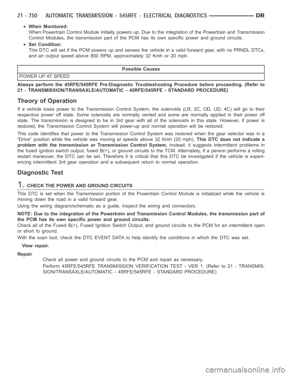
When Monitored:
When Powertrain Control Module initially powers up. Due to the integration of the Powertrain and Transmission
Control Modules, the transmission part of the PCM has its own specific power and ground circuits.
Set Condition:
This DTC will set if the PCM powers up and senses the vehicle in a valid forwardgear,withnoPRNDLDTCs,
and an output speed above 800 RPM, approximately 32 Kmh or 20 mph.
Possible Causes
POWER UP AT SPEED
Always perform the 45RFE/545RFE Pre-Diagnostic Troubleshooting Procedure before proceeding. (Refer to
21 - TRANSMISSION/TRANSAXLE/AUTOMATIC - 45RFE/545RFE - STANDARD PROCEDURE)
Theory of Operation
If a vehicle loses power to the Transmission Control System, the solenoids(LR, 2C, OD, UD, 4C) will go to their
respective power off state. Some solenoids are normally vented and some are normally applied in their power off
state. The transmission is designed to be in 3rd gear with all of the solenoids in this state. However, if power is
restored, the Transmission Control System will power-up and normal operation will be restored.
This code identifies that power to the Transmission Control System was restored when the gear selector was in a
Driveposition while the vehicle was moving at speeds above 32 Kmh (20 mph).This DTC does not indicate a
problem with the transmission or Transmission Control System,instead, it suggests intermittent problems in
the fused ignition switch output, fused B(+), or ground circuits to the TCM. Alternately, if a person performs a rolling
restart maneuver, the DTC can be set. Therefore it is critical that this DTCbe investigated if the vehicle is experi-
encing intermittent 3rd gear operation and a subsequent return to normal operation.
Diagnostic Test
1.CHECK THE POWER AND GROUND CIRCUITS
This DTC is set when the Transmission portion of the Powertrain Control Module is initialized while the vehicle is
movingdowntheroadinavalidforwardgear.
Using the wiring diagram/schematic as a guide, inspect the wiring and connectors.
NOTE: Due to the integration of the Powertrain and Transmission Control Modules, the transmission part of
the PCM has its own specific power and ground circuits.
Check all of the Fused B(+), Fused Ignition Switch Output, and ground circuits to the PCM for an intermittent open
or short to ground.
With the scan tool, check the DTC EVENT DATA to help identify the conditionsin which the DTC was set.
View repair.
Repair
Check all power and ground circuits to the PCM and repair as necessary.
Perform 45RFE/545RFE TRANSMISSION VERIFICATION TEST - VER 1. (Refer to 21- TRANSMIS-
SION/TRANSAXLE/AUTOMATIC - 45RFE/545RFE - STANDARD PROCEDURE)
Page 3275 of 5267

5.CHECK THE WIRING AND CONNECTORS
The conditions necessary to set this DTC are not present at this time.
Using the schematics as a guide, inspect the wiring and connectors specifictothiscircuit.
Wiggle the wires while checking for shorted and open circuits.
With the scan tool, check the DTC EVENT DATA to help identify the conditionsin which the DTC was set.
Where there any problems found?
Ye s>>
Repair as necessary.
Perform 45RFE/545RFE TRANSMISSION VERIFICATION TEST - VER 1. (Refer to 21- TRANSMIS-
SION/TRANSAXLE/AUTOMATIC - 45RFE/545RFE - STANDARD PROCEDURE)
No>>
Te s t C o m p l e t e .
Page 3278 of 5267
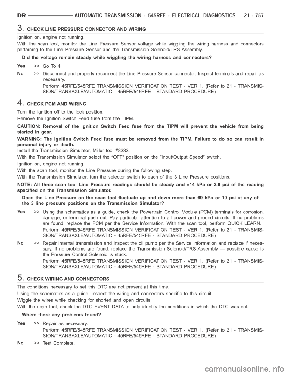
3.CHECK LINE PRESSURE CONNECTOR AND WIRING
Ignition on, engine not running.
With the scan tool, monitor the Line Pressure Sensor voltage while wiggling the wiring harness and connectors
pertaining to the Line Pressure Sensor and the Transmission Solenoid/TRSAssembly.
Did the voltage remain steady while wiggling the wiring harness and connectors?
Ye s>>
Go To 4
No>>
Disconnect and properly reconnect the Line Pressure Sensor connector. Inspect terminals and repair as
necessary.
Perform 45RFE/545RFE TRANSMISSION VERIFICATION TEST - VER 1. (Refer to 21- TRANSMIS-
SION/TRANSAXLE/AUTOMATIC - 45RFE/545RFE - STANDARD PROCEDURE)
4.CHECK PCM AND WIRING
Turn the ignition off to the lock position.
Remove the Ignition Switch Feed fuse from the TIPM.
CAUTION: Removal of the Ignition Switch Feed fuse from the TIPM will prevent the vehicle from being
startedingear.
WARNING: The Ignition Switch Feed fuse must be removed from the TIPM. Failure to do so can result in
personal injury or death.
Install the Transmission Simulator, Miller tool #8333.
With the Transmission Simulator select the
OFFposition on theInput/Output Speedswitch.
Ignition on, engine not running.
With the scan tool, monitor the Line Pressure during the following step.
With the Transmission Simulator, turn the selector switch to each of the 3 Line Pressure positions.
NOTE: All three scan tool Line Pressure readings should be steady and ±14 kPa or 2.0 psi of the reading
specified on the Transmission Simulator.
Does the Line Pressure on the scan tool fluctuate up and down more than 69 kPaor 10 psi at any of
the 3 line pressure positions on the Transmission Simulator?
Ye s>>
Using the schematics as a guide, check the Powertrain Control Module (PCM)terminals for corrosion,
damage, or terminal push out. Pay particular attention to all power and ground circuits. If no problems
are found, replace the PCM per the Service Information. With the scan tool,perform QUICK LEARN.
Perform 45RFE/545RFE TRANSMISSION VERIFICATION TEST - VER 1. (Refer to 21- TRANSMIS-
SION/TRANSAXLE/AUTOMATIC - 45RFE/545RFE - STANDARD PROCEDURE)
No>>
Repair internal transmission and inspect the oil pump per the Service information and replace if neces-
sary. If no problems are found, replace the Transmission Solenoid/TRS Assembly — possible cause is
the Pressure Control Solenoid is stuck.
Perform 45RFE/545RFE TRANSMISSION VERIFICATION TEST - VER 1. (Refer to 21- TRANSMIS-
SION/TRANSAXLE/AUTOMATIC - 45RFE/545RFE - STANDARD PROCEDURE)
5.CHECK WIRING AND CONNECTORS
The conditions necessary to set this DTC are not present at this time.
Using the schematics as a guide, inspect the wiring and connectors specifictothiscircuit.
Wiggle the wires while checking for shorted and open circuits.
With the scan tool, check the DTC EVENT DATA to help identify the conditionsin which the DTC was set.
Where there any problems found?
Ye s>>
Repair as necessary.
Perform 45RFE/545RFE TRANSMISSION VERIFICATION TEST - VER 1. (Refer to 21- TRANSMIS-
SION/TRANSAXLE/AUTOMATIC - 45RFE/545RFE - STANDARD PROCEDURE)
No>>
Te s t C o m p l e t e .
Page 3283 of 5267

6.INTERMITTENT WIRING AND CONNECTORS
The conditions necessary to set this DTC are not present at this time.
Using the schematics as a guide, inspect the wiring and connectors specifictothiscircuit.
Wiggle the wires while checking for shorted and open circuits.
With the scan tool, check the DTC EVENT DATA to help identify the conditionsin which the DTC was set.
Where there any problems found?
Ye s>>
Repair as necessary.
Perform 45RFE/545RFE TRANSMISSION VERIFICATION TEST - VER 1. (Refer to 21- TRANSMIS-
SION/TRANSAXLE/AUTOMATIC - 45RFE/545RFE - STANDARD PROCEDURE)
No>>
Te s t C o m p l e t e .
Page 3288 of 5267

6.CHECK WIRING AND CONNECTORS
The conditions necessary to set this DTC are not present at this time.
Using the schematics as a guide, inspect the wiring and connectors specifictothiscircuit.
Wiggle the wires while checking for shorted and open circuits.
With the scan tool, check the DTC EVENT DATA to help identify the conditionsin which the DTC was set.
Where there any problems found?
Ye s>>
Repair as necessary.
Perform 45RFE/545RFE TRANSMISSION VERIFICATION TEST - VER 1. (Refer to 21- TRANSMIS-
SION/TRANSAXLE/AUTOMATIC - 45RFE/545RFE - STANDARD PROCEDURE)
No>>
Te s t C o m p l e t e .
Page 3290 of 5267
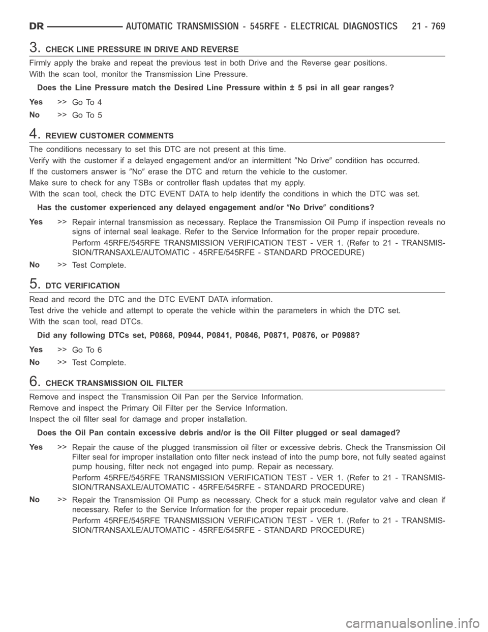
3.CHECK LINE PRESSURE IN DRIVE AND REVERSE
Firmly apply the brake and repeat the previous test in both Drive and the Reverse gear positions.
With the scan tool, monitor the Transmission Line Pressure.
Does the Line Pressure match the Desired Line Pressure within ± 5 psi in all gear ranges?
Ye s>>
Go To 4
No>>
Go To 5
4.REVIEW CUSTOMER COMMENTS
The conditions necessary to set this DTC are not present at this time.
Verify with the customer if a delayed engagement and/or an intermittent
No Drivecondition has occurred.
If the customers answer is
Noerase the DTC and return the vehicle to the customer.
Make sure to check for any TSBs or controller flash updates that my apply.
With the scan tool, check the DTC EVENT DATA to help identify the conditionsin which the DTC was set.
Has the customer experienced any delayed engagement and/or
No Driveconditions?
Ye s>>
Repair internal transmission as necessary. Replace the Transmission OilPump if inspection reveals no
signs of internal seal leakage. Refer to the Service Information for the proper repair procedure.
Perform 45RFE/545RFE TRANSMISSION VERIFICATION TEST - VER 1. (Refer to 21- TRANSMIS-
SION/TRANSAXLE/AUTOMATIC - 45RFE/545RFE - STANDARD PROCEDURE)
No>>
Te s t C o m p l e t e .
5.DTC VERIFICATION
Read and record the DTC and the DTC EVENT DATA information.
Test drive the vehicle and attempt to operate the vehicle within the parameters in which the DTC set.
With the scan tool, read DTCs.
Did any following DTCs set, P0868, P0944, P0841, P0846, P0871, P0876, or P0988?
Ye s>>
Go To 6
No>>
Te s t C o m p l e t e .
6.CHECK TRANSMISSION OIL FILTER
Remove and inspect the Transmission Oil Pan per the Service Information.
Remove and inspect the Primary Oil Filter per the Service Information.
Inspect the oil filter seal for damage and proper installation.
Does the Oil Pan contain excessive debris and/or is the Oil Filter plugged or seal damaged?
Ye s>>
Repair the cause of the plugged transmission oil filter or excessive debris. Check the Transmission Oil
Filter seal for improper installation onto filter neck instead of into thepump bore, not fully seated against
pump housing, filter neck not engaged into pump. Repair as necessary.
Perform 45RFE/545RFE TRANSMISSION VERIFICATION TEST - VER 1. (Refer to 21- TRANSMIS-
SION/TRANSAXLE/AUTOMATIC - 45RFE/545RFE - STANDARD PROCEDURE)
No>>
Repair the Transmission Oil Pump as necessary. Check for a stuck main regulator valve and clean if
necessary. Refer to the Service Information for the proper repair procedure.
Perform 45RFE/545RFE TRANSMISSION VERIFICATION TEST - VER 1. (Refer to 21- TRANSMIS-
SION/TRANSAXLE/AUTOMATIC - 45RFE/545RFE - STANDARD PROCEDURE)
Page 3298 of 5267
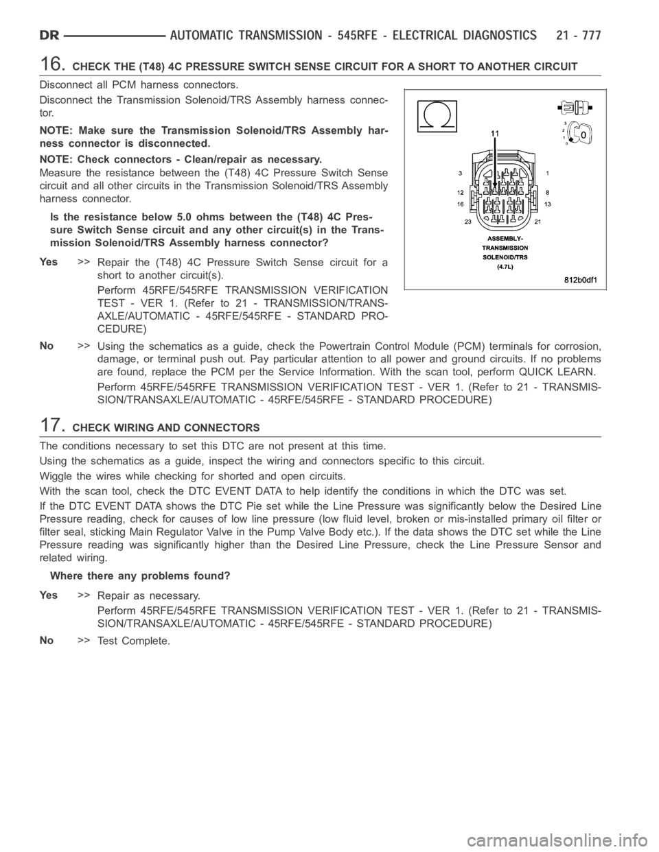
16.CHECK THE (T48) 4C PRESSURE SWITCH SENSE CIRCUIT FOR A SHORT TO ANOTHER CIRCUIT
Disconnect all PCM harness connectors.
Disconnect the Transmission Solenoid/TRS Assembly harness connec-
tor.
NOTE: Make sure the Transmission Solenoid/TRS Assembly har-
ness connector is disconnected.
NOTE: Check connectors - Clean/repair as necessary.
Measure the resistance between the (T48) 4C Pressure Switch Sense
circuit and all other circuits in the Transmission Solenoid/TRS Assembly
harness connector.
Is the resistance below 5.0 ohms between the (T48) 4C Pres-
sure Switch Sense circuit and any other circuit(s) in the Trans-
mission Solenoid/TRS Assembly harness connector?
Ye s>>
Repair the (T48) 4C Pressure Switch Sense circuit for a
short to another circuit(s).
Perform 45RFE/545RFE TRANSMISSION VERIFICATION
TEST - VER 1. (Refer to 21 - TRANSMISSION/TRANS-
AXLE/AUTOMATIC - 45RFE/545RFE - STANDARD PRO-
CEDURE)
No>>
Using the schematics as a guide, check the Powertrain Control Module (PCM)terminals for corrosion,
damage, or terminal push out. Pay particular attention to all power and ground circuits. If no problems
are found, replace the PCM per the Service Information. With the scan tool,perform QUICK LEARN.
Perform 45RFE/545RFE TRANSMISSION VERIFICATION TEST - VER 1. (Refer to 21- TRANSMIS-
SION/TRANSAXLE/AUTOMATIC - 45RFE/545RFE - STANDARD PROCEDURE)
17.CHECK WIRING AND CONNECTORS
The conditions necessary to set this DTC are not present at this time.
Using the schematics as a guide, inspect the wiring and connectors specifictothiscircuit.
Wiggle the wires while checking for shorted and open circuits.
With the scan tool, check the DTC EVENT DATA to help identify the conditionsin which the DTC was set.
If the DTC EVENT DATA shows the DTC Pie set while the Line Pressure was significantly below the Desired Line
Pressure reading, check for causes of low line pressure (low fluid level, broken or mis-installed primary oil filter or
filter seal, sticking Main Regulator Valve in the Pump Valve Body etc.). IfthedatashowstheDTCsetwhiletheLine
Pressure reading was significantly higher than the Desired Line Pressure, check the Line Pressure Sensor and
related wiring.
Where there any problems found?
Ye s>>
Repair as necessary.
Perform 45RFE/545RFE TRANSMISSION VERIFICATION TEST - VER 1. (Refer to 21- TRANSMIS-
SION/TRANSAXLE/AUTOMATIC - 45RFE/545RFE - STANDARD PROCEDURE)
No>>
Te s t C o m p l e t e .
Page 3306 of 5267
When Monitored:
With the ignition on. Battery voltage greater than 10 volts.
Set Condition:
A shorted condition is detected in the Transmission Control Output circuit.
Possible Causes
(T16) TRANSMISSION CONTROL OUTPUT CIRCUIT SHORT TO GROUND
(T16) TRANSMISSION CONTROL OUTPUT CIRCUIT FOR AN OPEN
TOTALLY INTEGRATED POWER MODULE (TIPM)
Diagnostic Test
1.CHECK IF THE DTC IS ACTIVE
Ignition on, engine not running.
With the scan tool, check TIPM DTCs.
Is the status Active for this DTC?
Ye s>>
Go to 2
No>>
Go to 5
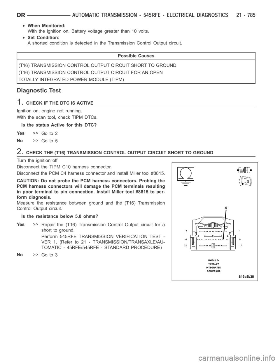
2.CHECK THE (T16) TRANSMISSION CONTROL OUTPUT CIRCUIT SHORT TO GROUND
Turn the ignition off
Disconnect the TIPM C10 harness connector.
Disconnect the PCM C4 harness connector and install Miller tool #8815.
CAUTION: Do not probe the PCM harness connectors. Probing the
PCM harness connectors will damage the PCM terminals resulting
in poor terminal to pin connection. Install Miller tool #8815 to per-
form diagnosis.
Measure the resistance between ground and the (T16) Transmission
Control Output circuit.
Is the resistance below 5.0 ohms?
Ye s>>
Repair the (T16) Transmission Control Output circuit for a
short to ground.
Perform 545RFE TRANSMISSION VERIFICATION TEST -
VER 1. (Refer to 21 - TRANSMISSION/TRANSAXLE/AU-
TOMATIC - 45RFE/545RFE - STANDARD PROCEDURE)
No>>
Go to 3