2006 DODGE RAM SRT-10 lock
[x] Cancel search: lockPage 2897 of 5267
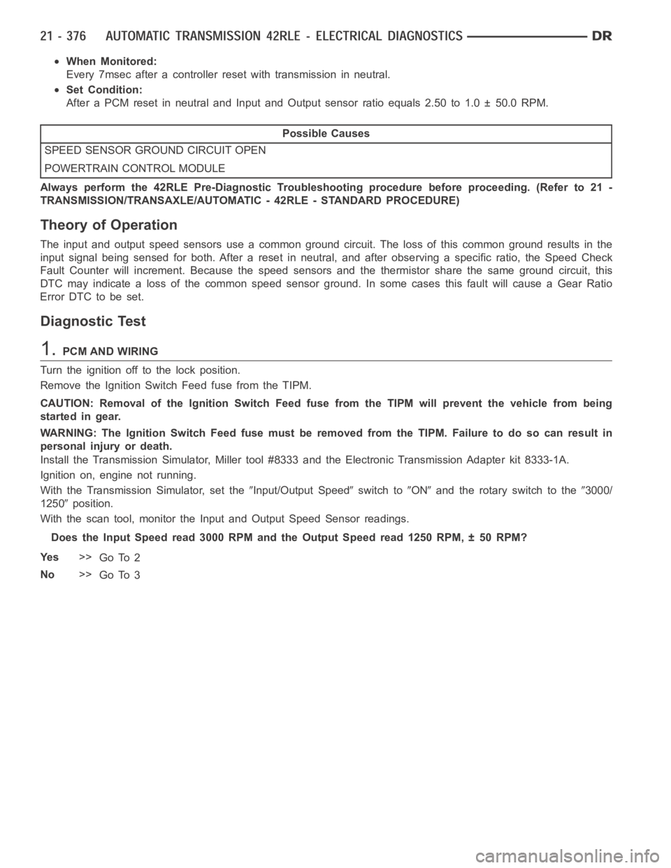
When Monitored:
Every 7msec after a controller reset with transmission in neutral.
Set Condition:
After a PCM reset in neutral and Input and Output sensor ratio equals 2.50 to1.0 ± 50.0 RPM.
Possible Causes
SPEED SENSOR GROUND CIRCUIT OPEN
POWERTRAIN CONTROL MODULE
Always perform the 42RLE Pre-Diagnostic Troubleshooting procedure before proceeding. (Refer to 21 -
TRANSMISSION/TRANSAXLE/AUTOMATIC - 42RLE - STANDARD PROCEDURE)
Theory of Operation
The input and output speed sensors use a common ground circuit. The loss of this common ground results in the
input signal being sensed for both. After a reset in neutral, and after observing a specific ratio, the Speed Check
Fault Counter will increment. Because the speed sensors and the thermistor share the same ground circuit, this
DTC may indicate a loss of the common speed sensor ground. In some cases thisfault will cause a Gear Ratio
Error DTC to be set.
Diagnostic Test
1.PCM AND WIRING
Turn the ignition off to the lock position.
Remove the Ignition Switch Feed fuse from the TIPM.
CAUTION: Removal of the Ignition Switch Feed fuse from the TIPM will prevent the vehicle from being
startedingear.
WARNING: The Ignition Switch Feed fuse must be removed from the TIPM. Failure to do so can result in
personal injury or death.
Install the Transmission Simulator,Miller tool #8333 and the ElectronicTransmission Adapter kit 8333-1A.
Ignition on, engine not running.
With the Transmission Simulator, set the
Input/Output Speedswitch toONand the rotary switch to the3000/
1250
position.
With the scan tool, monitor the Input and Output Speed Sensor readings.
Does the Input Speed read 3000 RPM and the Output Speed read 1250 RPM, ± 50 RPM?
Ye s>>
Go To 2
No>>
Go To 3
Page 2898 of 5267

2.(T13) SPEED SENSOR GROUND CIRCUIT OPEN
Turn the ignition off to the lock position.
Disconnect the PCM C4 harness connector.
Disconnect the Input and Output Speed Sensor harness connectors.
CAUTION: Do not probe the PCM harness connectors. Probing the
PCM harness connectors will damage the PCM terminals resulting
in poor terminal to pin connection. Install Miller tool #8815 to per-
form diagnosis.
Measure the resistance of both of the (T13) Speed Sensor Ground cir-
cuits from the appropriate terminal of special tool #8815 to the Input
and Output Speed Sensor harness connectors.
Is the resistance above 5.0 ohms on either circuit?
Ye s>>
Repair the (T13) Speed Sensor Ground circuit for an open.
Perform 42RLE TRANSMISSION VERIFICATION TEST -
VER 1. (Refer to 21 - TRANSMISSION/TRANSAXLE/AU-
TOMATIC - 42RLE - STANDARD PROCEDURE)
No>>
Using the schematics as a guide, check the Powertrain
Control Module (PCM) terminals for corrosion, damage, or
terminal push out. Pay particular attention to all power and
ground circuits. If no problems are found, replace the PCM
per the Service Information.With the scan tool, perform
QUICK LEARN
Perform 42RLE TRANSMISSION VERIFICATION TEST - VER 1. (Refer to 21 - TRANSMISSION/
TRANSAXLE/AUTOMATIC - 42RLE - STANDARD PROCEDURE)
3.INTERMITTENT WIRING AND CONNECTORS
The conditions necessary to set the DTC are not present at this time.
Using the schematics as a guide, inspect the wiring and connectors specifictothiscircuit.
Wiggle the wires while checking for shorted and open circuits.
With the scan tool, check the DTC EVENT DATA to help identify the conditionsin which the DTC was set.
Were there any problems found?
Ye s>>
Repair as necessary.
Perform 42RLE TRANSMISSION VERIFICATION TEST - VER 1. (Refer to 21 - TRANSMISSION/
TRANSAXLE/AUTOMATIC - 42RLE - STANDARD PROCEDURE)
No>>
Te s t C o m p l e t e .
Page 2910 of 5267
page page
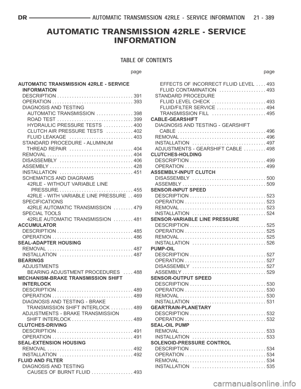
AUTOMATIC TRANSMISSION 42RLE - SERVICE
INFORMATION
DESCRIPTION ............................... 391
OPERATION ................................. 393
DIAGNOSIS AND TESTING
AUTOMATIC TRANSMISSION ............... 398
ROAD TEST ............................... 399
HYDRAULIC PRESSURE TESTS............ 400
CLUTCH AIR PRESSURE TESTS........... 402
FLUID LEAKAGE.......................... 403
STANDARD PROCEDURE - ALUMINUM
THREAD REPAIR .......................... 404
REMOVAL ................................... 404
DISASSEMBLY .............................. 406
ASSEMBLY .................................. 428
INSTALLATION .............................. 451
SCHEMATICS AND DIAGRAMS
42RLE - WITHOUT VARIABLE LINE
PRESSURE............................... 455
42RLE - WITH VARIABLE LINE PRESSURE . . 469
SPECIFICATIONS
42RLE AUTOMATIC TRANSMISSION ........ 479
SPECIAL TOOLS
42RLE AUTOMATIC TRANSMISSION ........ 481
ACCUMULATOR
DESCRIPTION ............................... 485
OPERATION ................................. 486
SEAL-ADAPTER HOUSING
REMOVAL ................................... 487
INSTALLATION .............................. 487
BEARINGS
ADJUSTMENTS
BEARING ADJUSTMENT PROCEDURES.... 488
MECHANISM-BRAKE TRANSMISSION SHIFT
INTERLOCK
DESCRIPTION ............................... 489
OPERATION ................................. 489
DIAGNOSIS AND TESTING - BRAKE
TRANSMISSION SHIFT INTERLOCK ......... 489
ADJUSTMENTS - BRAKE TRANSMISSION
SHIFT INTERLOCK ......................... 489
CLUTCHES-DRIVING
DESCRIPTION ............................... 491
OPERATION ................................. 491
SEAL-EXTENSION HOUSING
REMOVAL ................................... 492
INSTALLATION .............................. 492
FLUID AND FILTER
DIAGNOSIS AND TESTING
CAUSES OF BURNT FLUID ................. 493EFFECTS OF INCORRECT FLUID LEVEL . . . . 493
FLUID CONTAMINATION ................... 493
STANDARD PROCEDURE
FLUID LEVEL CHECK...................... 493
FLUID/FILTER SERVICE .................... 494
TRANSMISSION FILL ...................... 495
CABLE-GEARSHIFT
DIAGNOSIS AND TESTING - GEARSHIFT
CABLE .................................... 496
REMOVAL ................................... 496
INSTALLATION .............................. 497
ADJUSTMENTS - GEARSHIFT CABLE ......... 498
CLUTCHES-HOLDING
DESCRIPTION ............................... 499
OPERATION ................................. 499
ASSEMBLY-INPUT CLUTCH
DISASSEMBLY .............................. 500
ASSEMBLY .................................. 509
SENSOR-INPUT SPEED
DESCRIPTION ............................... 523
OPERATION ................................. 523
REMOVAL ................................... 523
INSTALLATION .............................. 524
SENSOR-VARIABLE LINE PRESSURE
DESCRIPTION ............................... 525
OPERATION ................................. 525
REMOVAL ................................... 525
INSTALLATION .............................. 526
PUMP-OIL
DESCRIPTION ............................... 527
OPERATION ................................. 527
DISASSEMBLY .............................. 527
ASSEMBLY .................................. 529
SENSOR-OUTPUT SPEED
DESCRIPTION ............................... 530
OPERATION ................................. 530
REMOVAL ................................... 530
INSTALLATION .............................. 531
GEARTRAIN-PLANETARY
DESCRIPTION ............................... 532
OPERATION ................................. 532
SEAL-OIL PUMP
REMOVAL ................................... 533
INSTALLATION .............................. 533
SOLENOID-PRESSURE CONTROL
DESCRIPTION ............................... 534
OPERATION ................................. 534
REMOVAL ................................... 534
INSTALLATION .............................. 535
Page 2917 of 5267
THIRDGEARPOWERFLOW
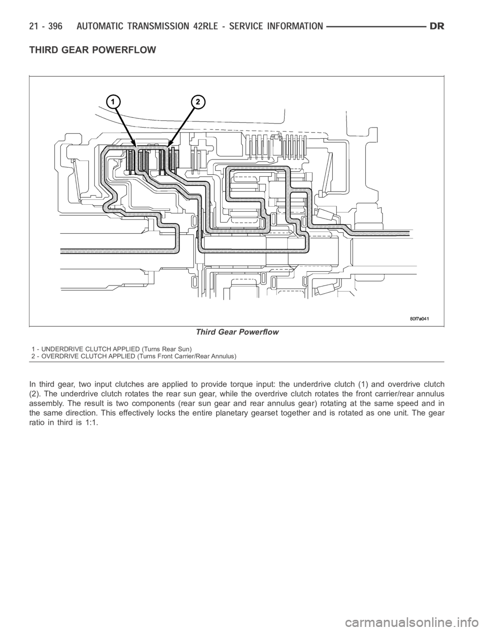
In third gear, two input clutches are applied to provide torque input: the underdrive clutch (1) and overdrive clutch
(2). The underdrive clutch rotates the rear sun gear, while the overdrive clutch rotates the front carrier/rear annulus
assembly. The result is two components (rear sun gear and rear annulus gear) rotating at the same speed and in
the same direction. This effectively locks the entire planetary gearset together and is rotated as one unit. The gear
ratio in third is 1:1.
Third Gear Powerflow
1 - UNDERDRIVE CLUTCH APPLIED (Turns Rear Sun)
2 - OVERDRIVE CLUTCH APPLIED (Turns Front Carrier/Rear Annulus)
Page 2924 of 5267
OVERDRIVE CLUTCH
Apply air pressure to the overdrive clutch apply passage and watch for the push/pull piston to move forward. The
piston should return to its starting position when the air pressure is removed.
REVERSE CLUTCH
Apply air pressure to the reverse clutch apply passage and watch for the push/pull piston to move rearward. The
piston should return to its starting position when the air pressure is removed.
LOW/REVERSE CLUTCH
Apply air pressure to the low/reverse clutch feed hole passage. Look in thearea where the low/reverse piston con-
tacts the first separator plate. Watch carefully for the piston to move forward. The piston should return to its original
position after the air pressure is removed.
UNDERDRIVE CLUTCH
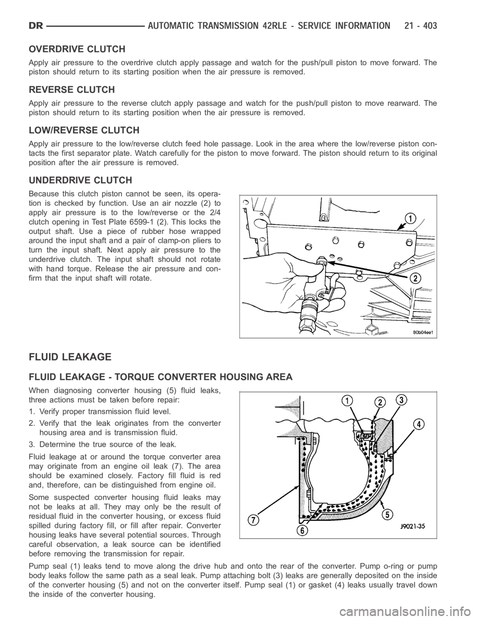
Because this clutch piston cannot be seen, its opera-
tion is checked by function. Use an air nozzle (2) to
apply air pressure is to the low/reverse or the 2/4
clutch opening in Test Plate 6599-1 (2). This locks the
output shaft. Use a piece of rubber hose wrapped
around the input shaft and a pair of clamp-on pliers to
turn the input shaft. Next apply air pressure to the
underdrive clutch. The input shaft should not rotate
with hand torque. Release the air pressure and con-
firm that the input shaft will rotate.
FLUID LEAKAGE
FLUID LEAKAGE - TORQUE CONVERTER HOUSING AREA
When diagnosing converter housing (5) fluid leaks,
three actions must be taken before repair:
1. Verify proper transmission fluid level.
2. Verify that the leak originates from the converter
housing area and is transmission fluid.
3. Determine the true source of the leak.
Fluid leakage at or around the torque converter area
may originate from an engine oil leak (7). The area
should be examined closely. Factory fill fluid is red
and, therefore, can be distinguished from engine oil.
Some suspected converter housing fluid leaks may
not be leaks at all. They may only be the result of
residual fluid in the converter housing, or excess fluid
spilled during factory fill, or fill after repair. Converter
housing leaks have several potential sources. Through
careful observation, a leak source can be identified
before removing the transmission for repair.
Pump seal (1) leaks tend to move along the drive hub and onto the rear of the converter. Pump o-ring or pump
body leaks follow the same path as a seal leak. Pump attaching bolt (3) leaksare generally deposited on the inside
of the converter housing (5) and not on the converter itself. Pump seal (1) or gasket (4) leaks usually travel down
the inside of the converter housing.
Page 2927 of 5267
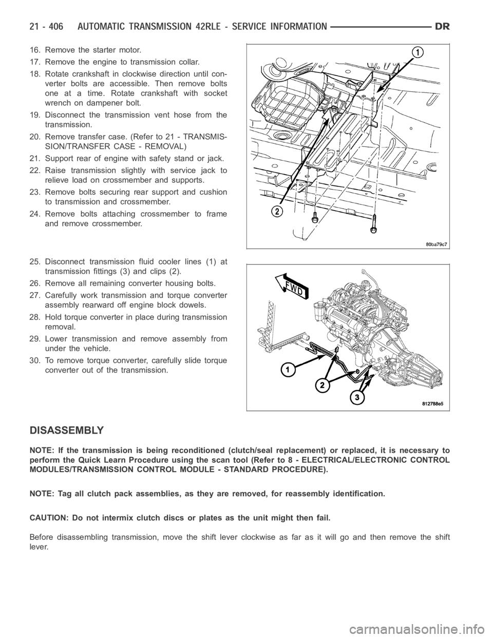
16. Remove the starter motor.
17. Remove the engine to transmission collar.
18. Rotate crankshaft in clockwise direction until con-
verter bolts are accessible. Then remove bolts
one at a time. Rotate crankshaft with socket
wrench on dampener bolt.
19. Disconnect the transmission vent hose from the
transmission.
20. Remove transfer case. (Refer to 21 - TRANSMIS-
SION/TRANSFER CASE - REMOVAL)
21. Support rear of engine with safety stand or jack.
22. Raise transmission slightly with service jack to
relieve load on crossmember and supports.
23. Remove bolts securing rear support and cushion
to transmission and crossmember.
24. Remove bolts attaching crossmember to frame
and remove crossmember.
25. Disconnect transmission fluid cooler lines (1) at
transmission fittings (3) and clips (2).
26. Remove all remaining converter housing bolts.
27. Carefully work transmission and torque converter
assembly rearward off engine block dowels.
28. Hold torque converter in place during transmission
removal.
29. Lower transmission and remove assembly from
under the vehicle.
30. To remove torque converter, carefully slide torque
converter out of the transmission.
DISASSEMBLY
NOTE: If the transmission is being reconditioned (clutch/seal replacement) or replaced, it is necessary to
perform the Quick Learn Procedure using the scan tool (Refer to 8 - ELECTRICAL/ELECTRONIC CONTROL
MODULES/TRANSMISSION CONTROL MODULE - STANDARD PROCEDURE).
NOTE: Tag all clutch pack assemblies, as they are removed, for reassembly identification.
CAUTION: Do not intermix clutch discs or plates as the unit might then fail.
Before disassembling transmission, move the shift lever clockwise as faras it will go and then remove the shift
lever.
Page 2941 of 5267
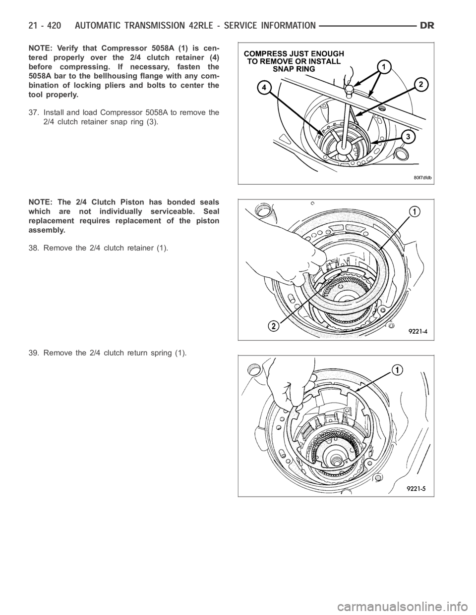
NOTE: Verify that Compressor 5058A (1) is cen-
tered properly over the 2/4 clutch retainer (4)
before compressing. If necessary, fasten the
5058A bar to the bellhousing flange with any com-
bination of locking pliers and bolts to center the
tool properly.
37. Install and load Compressor 5058A to remove the
2/4 clutch retainer snap ring (3).
NOTE: The 2/4 Clutch Piston has bonded seals
which are not individually serviceable. Seal
replacement requires replacement of the piston
assembly.
38. Remove the 2/4 clutch retainer (1).
39. Remove the 2/4 clutch return spring (1).
Page 2960 of 5267
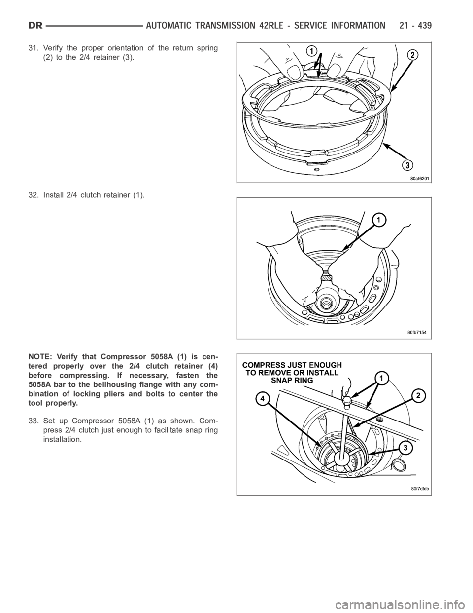
31. Verify the proper orientation of the return spring
(2) to the 2/4 retainer (3).
32. Install 2/4 clutch retainer (1).
NOTE: Verify that Compressor 5058A (1) is cen-
tered properly over the 2/4 clutch retainer (4)
before compressing. If necessary, fasten the
5058A bar to the bellhousing flange with any com-
bination of locking pliers and bolts to center the
tool properly.
33. Set up Compressor 5058A (1) as shown. Com-
press 2/4 clutch just enough to facilitate snap ring
installation.