Page 2741 of 5267

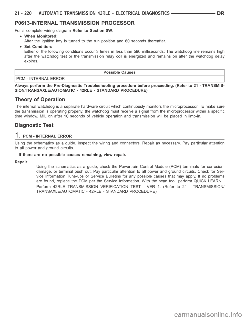
P0613-INTERNAL TRANSMISSION PROCESSOR
For a complete wiring diagramRefer to Section 8W.
When Monitored:
After the ignition key is turned to the run position and 60 seconds thereafter.
Set Condition:
Either of the following conditions occur 3 times in less than 590 milliseconds: The watchdog line remains high
after the watchdog test or the transmission relay coil is energized and remains on after the watchdog delay
expires.
Possible Causes
PCM - INTERNAL ERROR
Always perform the Pre-Diagnostic Troubleshooting procedure before proceeding. (Refer to 21 - TRANSMIS-
SION/TRANSAXLE/AUTOMATIC - 42RLE - STANDARD PROCEDURE)
Theory of Operation
The internal watchdog is a separate hardware circuit which continuously monitors the microprocessor. To make sure
the transmission is operating properly, the watchdog must receive a signal from the microprocessor within a specific
time window. MIL on after 10 seconds of vehicle operation and transmissionwill be placed in limp-in.
Diagnostic Test
1.PCM - INTERNAL ERROR
Using the schematics as a guide, inspect the wiring and connectors. Repairas necessary. Pay particular attention
to all power and ground circuits.
If there are no possible causes remaining, view repair.
Repair
Using the schematics as a guide, check the Powertrain Control Module (PCM)terminals for corrosion,
damage, or terminal push out. Pay particular attention to all power and ground circuits. Check for Ser-
vice Information Tune-ups or Service Bulletins for any possible causes that may apply. If no problems
are found, replace the PCM per the Service Information. With the scan tool,perform QUICK LEARN.
Perform 42RLE TRANSMISSION VERIFICATION TEST - VER 1. (Refer to 21 - TRANSMISSION/
TRANSAXLE/AUTOMATIC - 42RLE - STANDARD PROCEDURE)
Page 2742 of 5267
P0706-TRANSMISSION RANGE SENSOR RATIONALITY
For a complete wiring diagramRefer to Section 8W.
Page 2746 of 5267
P0711-TRANSMISSION TEMPERATURE SENSOR PERFORMANCE
For a complete wiring diagramRefer to Section 8W.
Page 2749 of 5267
P0712-TRANSMISSION TEMPERATURE SENSOR LOW
For a complete wiring diagramRefer to Section 8W.
Page 2752 of 5267
P0713-TRANSMISSION TEMPERATURE SENSOR HIGH
For a complete wiring diagramRefer to Section 8W.
Page 2756 of 5267
P0714-TRANSMISSION TEMPERATURE SENSOR INTERMITTENT
For a complete wiring diagramRefer to Section 8W.
Page 2759 of 5267
P0715-INPUT SPEED SENSOR 1 CIRCUIT
For a complete wiring diagramRefer to Section 8W.
Page 2764 of 5267
P0720-OUTPUT SPEED SENSOR CIRCUIT
For a complete wiring diagramRefer to Section 8W.