Page 898 of 5267
U0001-CAN C BUS
For a complete wiring diagramRefer to Section 8W.
Page 900 of 5267
U0121-LOST COMMUNICATION WITH ANTI-LOCK BRAKE MODULE
For a complete wiring diagramRefer to Section 8W.
Page 902 of 5267
U0141-LOST COMMUNICATION WITH TIP MODULE
For a complete wiring diagramRefer to Section 8W.
Page 904 of 5267

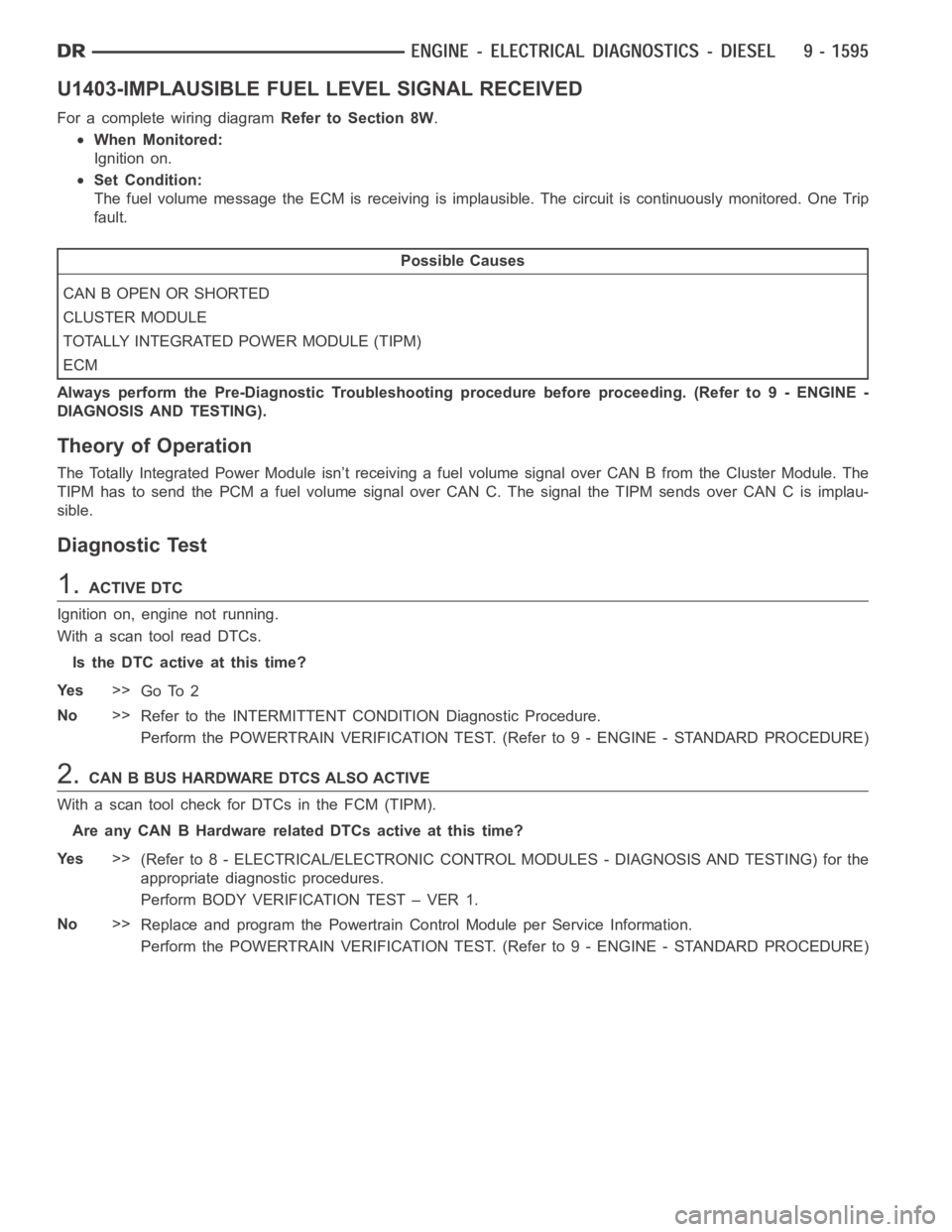
U1403-IMPLAUSIBLE FUEL LEVEL SIGNAL RECEIVED
For a complete wiring diagramRefer to Section 8W.
When Monitored:
Ignition on.
Set Condition:
The fuel volume message the ECM is receiving is implausible. The circuit iscontinuously monitored. One Trip
fault.
Possible Causes
CAN B OPEN OR SHORTED
CLUSTER MODULE
TOTALLY INTEGRATED POWER MODULE (TIPM)
ECM
Always perform the Pre-Diagnostic Troubleshooting procedure before proceeding. (Refer to 9 - ENGINE -
DIAGNOSIS AND TESTING).
Theory of Operation
The Totally Integrated Power Module isn’t receiving a fuel volume signal over CAN B from the Cluster Module. The
TIPM has to send the PCM a fuel volume signal over CAN C. The signal the TIPM sendsoverCANCisimplau-
sible.
Diagnostic Test
1.ACTIVE DTC
Ignition on, engine not running.
With a scan tool read DTCs.
Is the DTC active at this time?
Ye s>>
Go To 2
No>>
Refer to the INTERMITTENT CONDITION Diagnostic Procedure.
Perform the POWERTRAIN VERIFICATION TEST. (Refer to 9 - ENGINE - STANDARD PROCEDURE)
2.CAN B BUS HARDWARE DTCS ALSO ACTIVE
With a scan tool check for DTCs in the FCM (TIPM).
Are any CAN B Hardware related DTCs active at this time?
Ye s>>
(Refer to 8 - ELECTRICAL/ELECTRONIC CONTROL MODULES - DIAGNOSIS AND TESTING) for the
appropriate diagnostic procedures.
Perform BODY VERIFICATION TEST – VER 1.
No>>
Replace and program the Powertrain Control Module per Service Information.
Perform the POWERTRAIN VERIFICATION TEST. (Refer to 9 - ENGINE - STANDARD PROCEDURE)
Page 905 of 5267

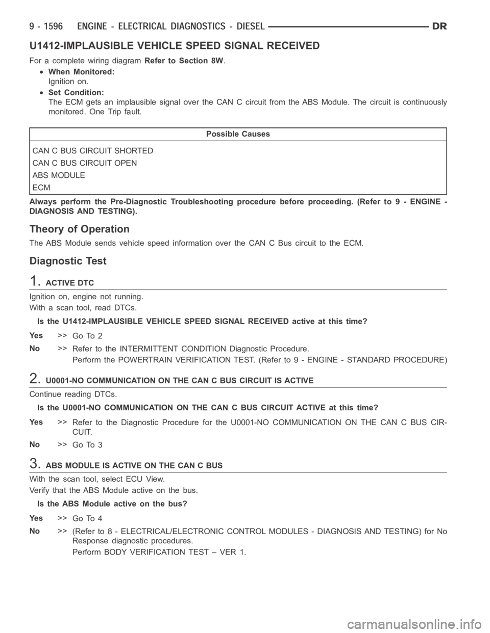
U1412-IMPLAUSIBLE VEHICLE SPEED SIGNAL RECEIVED
For a complete wiring diagramRefer to Section 8W.
When Monitored:
Ignition on.
Set Condition:
The ECM gets an implausible signal over the CAN C circuit from the ABS Module. The circuit is continuously
monitored. One Trip fault.
Possible Causes
CAN C BUS CIRCUIT SHORTED
CAN C BUS CIRCUIT OPEN
ABS MODULE
ECM
Always perform the Pre-Diagnostic Troubleshooting procedure before proceeding. (Refer to 9 - ENGINE -
DIAGNOSIS AND TESTING).
Theory of Operation
The ABS Module sends vehicle speed information over the CAN C Bus circuit tothe ECM.
Diagnostic Test
1.ACTIVE DTC
Ignition on, engine not running.
With a scan tool, read DTCs.
Is the U1412-IMPLAUSIBLE VEHICLE SPEED SIGNAL RECEIVED active at this time?
Ye s>>
Go To 2
No>>
Refer to the INTERMITTENT CONDITION Diagnostic Procedure.
Perform the POWERTRAIN VERIFICATION TEST. (Refer to 9 - ENGINE - STANDARD PROCEDURE)
2.U0001-NO COMMUNICATION ON THE CAN C BUS CIRCUIT IS ACTIVE
Continue reading DTCs.
Is the U0001-NO COMMUNICATION ON THE CAN C BUS CIRCUIT ACTIVE at this time?
Ye s>>
Refer to the Diagnostic Procedure for the U0001-NO COMMUNICATION ON THE CANCBUSCIR-
CUIT.
No>>
Go To 3
3.ABS MODULE IS ACTIVE ON THE CAN C BUS
With the scan tool, select ECU View.
Verify that the ABS Module active on the bus.
Is the ABS Module active on the bus?
Ye s>>
Go To 4
No>>
(Refer to 8 - ELECTRICAL/ELECTRONIC CONTROL MODULES - DIAGNOSIS AND TESTING) for No
Response diagnostic procedures.
Perform BODY VERIFICATION TEST – VER 1.
Page 907 of 5267
U0141-LOST COMMUNICATION WITH ECU
For a complete wiring diagramRefer to Section 8W.
Page 909 of 5267

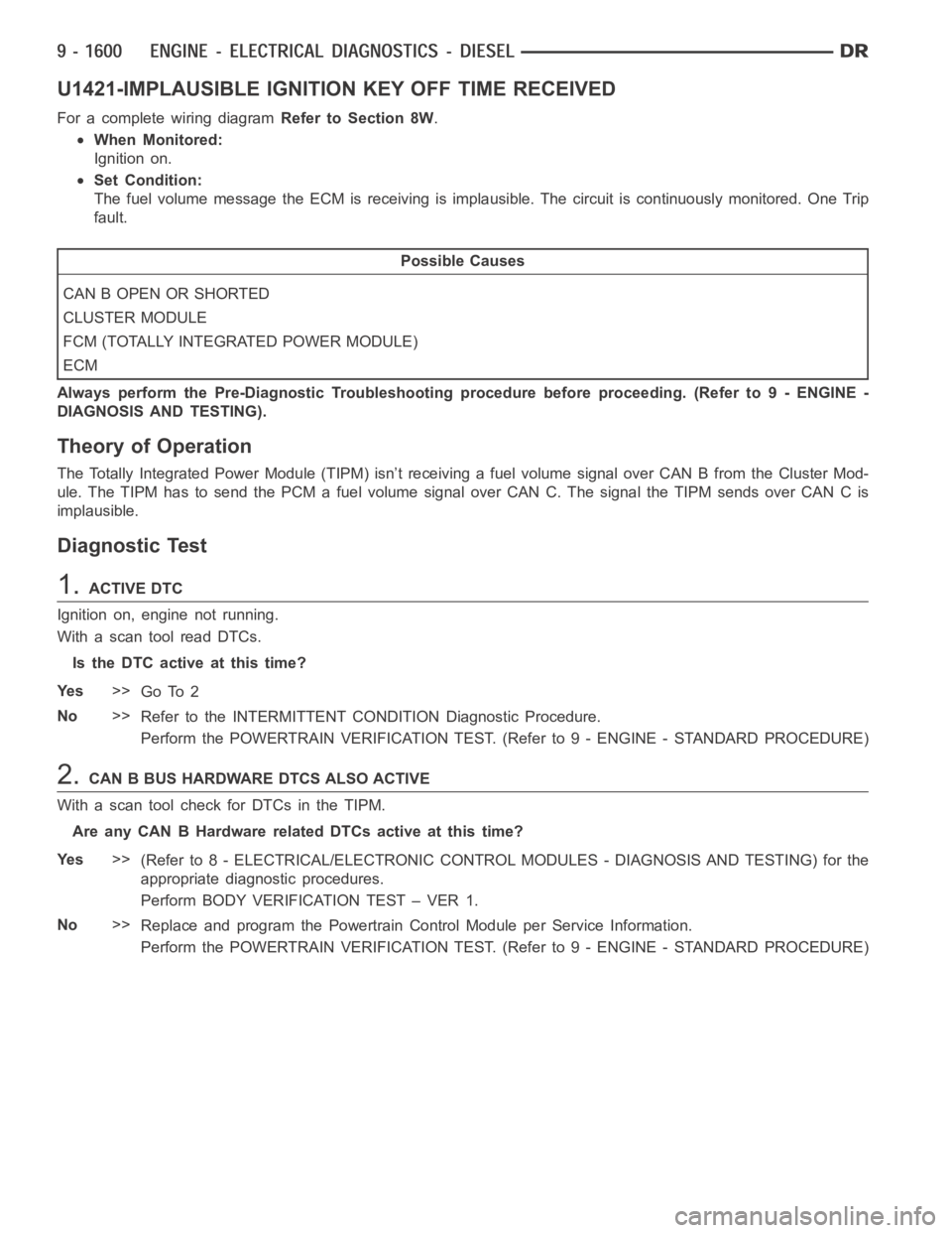
U1421-IMPLAUSIBLE IGNITION KEY OFF TIME RECEIVED
For a complete wiring diagramRefer to Section 8W.
When Monitored:
Ignition on.
Set Condition:
The fuel volume message the ECM is receiving is implausible. The circuit iscontinuously monitored. One Trip
fault.
Possible Causes
CAN B OPEN OR SHORTED
CLUSTER MODULE
FCM (TOTALLY INTEGRATED POWER MODULE)
ECM
Always perform the Pre-Diagnostic Troubleshooting procedure before proceeding. (Refer to 9 - ENGINE -
DIAGNOSIS AND TESTING).
Theory of Operation
The Totally Integrated Power Module (TIPM) isn’t receiving a fuel volume signal over CAN B from the Cluster Mod-
ule. The TIPM has to send the PCM a fuel volume signal over CAN C. The signal the TIPM sends over CAN C is
implausible.
Diagnostic Test
1.ACTIVE DTC
Ignition on, engine not running.
With a scan tool read DTCs.
Is the DTC active at this time?
Ye s>>
Go To 2
No>>
Refer to the INTERMITTENT CONDITION Diagnostic Procedure.
Perform the POWERTRAIN VERIFICATION TEST. (Refer to 9 - ENGINE - STANDARD PROCEDURE)
2.CAN B BUS HARDWARE DTCS ALSO ACTIVE
With a scan tool check for DTCs in the TIPM.
Are any CAN B Hardware related DTCs active at this time?
Ye s>>
(Refer to 8 - ELECTRICAL/ELECTRONIC CONTROL MODULES - DIAGNOSIS AND TESTING) for the
appropriate diagnostic procedures.
Perform BODY VERIFICATION TEST – VER 1.
No>>
Replace and program the Powertrain Control Module per Service Information.
Perform the POWERTRAIN VERIFICATION TEST. (Refer to 9 - ENGINE - STANDARD PROCEDURE)
Page 916 of 5267

INTERMITTENT CONDITION
For a complete wiring diagramRefer to Section 8W.
POSSIBLE CAUSES
INTERMITTENT CONDITION
Diagnostic Test
1.INTERMITTENT CONDITION
NOTE: The conditions that set the DTC are not present at this time. The following list may help in identi-
fying the intermittent condition.
WARNING: When the engine is operating, do not stand in direct line with the fan. Do not put your hands
near the pulleys, belts, or fan. Do notwear loose clothing. Failure to follow these instructions can result in
personal injury or death.
Refer to any Technical Service Bulletins (TSBs) that may apply.
Review the scan tool Freeze Frame information. If possible, try to duplicate the conditions under which the DTC set.
With the engine running at normal operating temperature, monitor the scantool parameters relatedtotheDTCwhile
wiggling the wire harness. Look for parameter values to change and/or a DTCto set.
Turn the ignition off.
Visually inspect the related wire harness. Disconnect all the related harness connectors. Look for any chafed,
pierced, pinched, partially broken wires and broken, bent, pushed out, orcorroded terminals.
Perform a voltage drop test on the related circuits between the suspected faulty component and the PCM.
Inspect and clean all PCM, engine, and chassis grounds that are related to the most current DTC.
If numerous trouble codes were set, use a wire schematic and look for any common ground or supply circuits.
For any Relay DTCs, actuate the Relay with the scan tool and wiggle the related wire harness to try to interrupt the
actuation.
For intermittent Evaporative Emission trouble codes perform a visual andphysical inspection of the related parts
including hoses and the Fuel Filler cap.
For intermittent Misfire DTC’s check for restrictions in the Intake and Exhaust system, proper installation of Sensors,
vacuum leaks, and binding components that are run by the accessory drive belt.
Use the scan tool to perform a System Test if one applies to failing component.
A co-pilot, data recorder, and/or lab scope should be used to help diagnoseintermittent conditions.
Were any problems found during the above inspections?
Ye s>>
Perform the necessary repairs.
Perform POWERTRAIN VERIFICATION TEST VER - 1.
No>>
Te s t C o m p l e t e .