2006 DODGE RAM SRT-10 air condition
[x] Cancel search: air conditionPage 969 of 5267
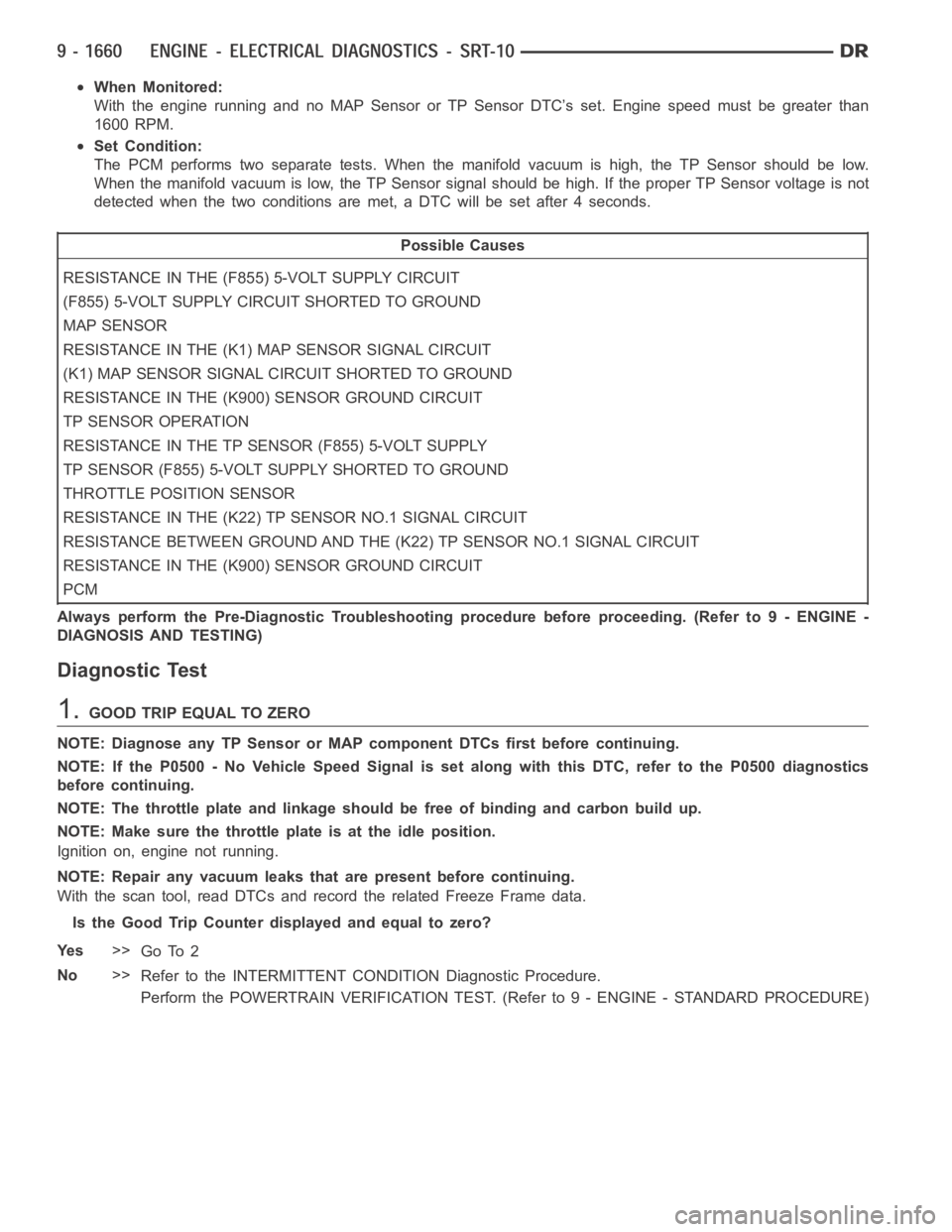
When Monitored:
With the engine running and no MAP Sensor or TP Sensor DTC’s set. Engine speed must be greater than
1600 RPM.
Set Condition:
The PCM performs two separate tests. When the manifold vacuum is high, the TP Sensor should be low.
When the manifold vacuum is low, the TP Sensor signal should be high. If the proper TP Sensor voltage is not
detected when the two conditions are met, a DTC will be set after 4 seconds.
Possible Causes
RESISTANCE IN THE (F855) 5-VOLT SUPPLY CIRCUIT
(F855) 5-VOLT SUPPLY CIRCUIT SHORTED TO GROUND
MAP SENSOR
RESISTANCE IN THE (K1) MAP SENSOR SIGNAL CIRCUIT
(K1) MAP SENSOR SIGNAL CIRCUIT SHORTED TO GROUND
RESISTANCE IN THE (K900) SENSOR GROUND CIRCUIT
TP SENSOR OPERATION
RESISTANCE IN THE TP SENSOR (F855) 5-VOLT SUPPLY
TP SENSOR (F855) 5-VOLT SUPPLY SHORTED TO GROUND
THROTTLE POSITION SENSOR
RESISTANCE IN THE (K22) TP SENSOR NO.1 SIGNAL CIRCUIT
RESISTANCE BETWEEN GROUND AND THE (K22) TP SENSOR NO.1 SIGNAL CIRCUIT
RESISTANCE IN THE (K900) SENSOR GROUND CIRCUIT
PCM
Always perform the Pre-Diagnostic Troubleshooting procedure before proceeding. (Refer to 9 - ENGINE -
DIAGNOSIS AND TESTING)
Diagnostic Test
1.GOOD TRIP EQUAL TO ZERO
NOTE: Diagnose any TP Sensor or MAP component DTCs first before continuing.
NOTE: If the P0500 - No Vehicle Speed Signal is set along with this DTC, referto the P0500 diagnostics
before continuing.
NOTE: The throttle plate and linkage should be free of binding and carbon build up.
NOTE: Make sure the throttle plate is at the idle position.
Ignition on, engine not running.
NOTE: Repair any vacuum leaks that are present before continuing.
With the scan tool, read DTCs and record the related Freeze Frame data.
Is the Good Trip Counter displayed and equal to zero?
Ye s>>
Go To 2
No>>
Refer to the INTERMITTENT CONDITION Diagnostic Procedure.
Perform the POWERTRAIN VERIFICATION TEST. (Refer to 9 - ENGINE - STANDARD PROCEDURE)
Page 970 of 5267
2.MAP SENSOR OPERATION
Start the engine.
With the scan tool, monitor the MAP Sensor voltage.
Snap the throttle.
Does the scan tool display MAP voltage from below 2.0 volts at idle to above 3.5 volts at WOT?
Ye s>>
Go To 3
No>>
Go To 10
3.TP SENSOR OPERATION
Ignition on, engine not running.
With the scan tool, monitor the TP Sensor voltage while slowly depressing the throttle pedal from the idle position
to the wide open throttle position.
Does voltage start at approximately 0.8 of a volt and go above 3.5 volts witha smooth transition?
Ye s>>
Refer to the INTERMITTENT CONDITION Diagnostic Procedure. (Refer to 9 - ENGINE - DIAGNOSIS
AND TESTING)
Perform the POWERTRAIN VERIFICATION TEST. (Refer to 9 - ENGINE - STANDARD PROCEDURE)
No>>
Go To 4
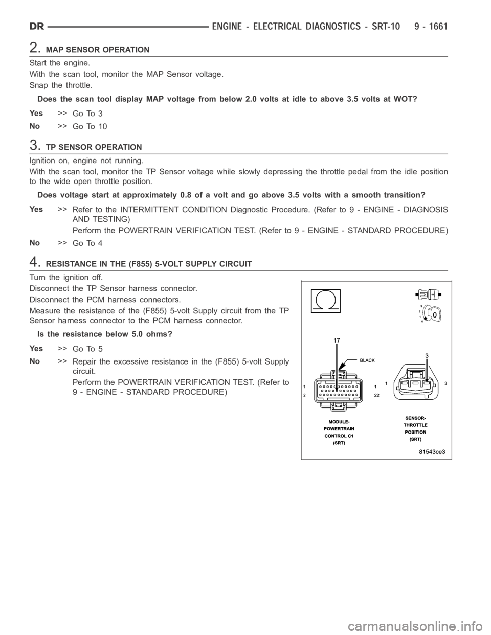
4.RESISTANCE IN THE (F855) 5-VOLT SUPPLY CIRCUIT
Turn the ignition off.
Disconnect the TP Sensor harness connector.
Disconnect the PCM harness connectors.
Measure the resistance of the (F855) 5-volt Supply circuit from the TP
Sensor harness connector to the PCM harness connector.
Is the resistance below 5.0 ohms?
Ye s>>
Go To 5
No>>
Repair the excessive resistance in the (F855) 5-volt Supply
circuit.
Perform the POWERTRAIN VERIFICATION TEST. (Refer to
9 - ENGINE - STANDARD PROCEDURE)
Page 987 of 5267

Theory of Operation
The engine coolant temperature sensor is a negative temperature coefficient thermistor-type sensor whose resis-
tance varies inversely with temperature. At cold temperatures the sensorresistance is high so the voltage is high.
As the coolant temperature increases the resistance decreases and the voltage becomes low. The INSUFFICIENT
COOLANT TEMP FOR CLOSED-LOOP FUEL CONTROL determines if the engine coolant temperature will reach
theclosedloopfuelingcontroltemperaturelimitinaregulatedtimeafterstart.
When Monitored:
With battery voltage greater than 10.4 volts and after engine is started.
Set Condition:
The engine temperature does not go above -10°C (15°F). Failure time depends on start-up coolant tempera-
ture and ambient temperature. (i.e. 2 minutes for a start temp of -10°C (15°F) or up to 10 minutes for a vehicle
with a start-up temp of -28°C (5°F). Two Trip Fault. Three good trips to turnoff the MIL.
Possible Causes
LOW COOLANT LEVEL
THERMOSTAT
ECT SENSOR
Always perform the Pre-Diagnostic Troubleshooting procedure before proceeding. (Refer to 9 - ENGINE -
DIAGNOSIS AND TESTING).
Diagnostic Test
1.CHECKING COOLANT LEVEL AND CONDITION
Ignition on, engine not running.
With a scan tool, read DTCs.
NOTE: If an Engine Coolant Temperature (ECT) DTC is set along with this code, diagnose the ECT DTC first.
NOTE: Inspect the ECT terminals and related PCM terminals. Make sure the terminals are free from corro-
sion and damage.
NOTE: The best way to diagnose this DTC is to allow the vehicle to sit overnight outside in order to have
a totally cold soaked engine.
NOTE: Extremely cold outside ambient temperatures may have caused this DTCtoset.
WARNING: Never open the cooling system when the engine is hot. The system isunder pressure. Extreme
burns or scalding may result. Failure to follow these instructions can result in personal injury or death.
Allow the engine to cool before opening the cooling system.
Inspect the coolant system for proper level and condition.
Is the coolant level and condition OK?
Ye s>>
Go To 2
No>>
Inspect the vehicle for a coolant leak, make the appropriate repairs, and add the correct amount of
coolant.
Perform the POWERTRAIN VERIFICATION TEST. (Refer to 9 - ENGINE - STANDARD PROCEDURE)
Page 993 of 5267

When Monitored:
With battery voltage greater than 10.4 volts, engine running for more than4 minutes and coolant temperature
above 180°F.
Set Condition:
The oxygen sensor voltage is above 1.5 volts.
Possible Causes
(K41) O2 1/1 SIGNAL CIRCUIT SHORTED TO VOLTAGE
(K99) O2 SENSOR 1/1 HEATER CONTROL CIRCUIT OPEN
(K41) O2 1/1 SIGNAL CIRCUIT OPEN
(K900) SENSOR GROUND CIRCUIT OPEN
(K343) ASD RELAY OUTPUT CIRCUIT OPEN
(K41) O2 1/1 SIGNAL CIRCUIT SHORTED TO THE (K343) ASD RELAY OUTPUT CIRCUIT
O2 SENSOR
PCM
Always perform the Pre-Diagnostic Troubleshooting procedure before proceeding. (Refer to 9 - ENGINE -
DIAGNOSIS AND TESTING).
Diagnostic Test
1.O2 SENSOR ABOVE 1.5 VOLTS
Ignition on, engine not running.
With the scan tool, read DTCs and record the related Freeze Frame data.
Start the engine.
Allow the engine to idle for 4 to 5 minutes.
With the scan tool, read the O2 Sensor voltage.
Is the voltage above 1.5 volts?
Ye s>>
Go To 2
No>>
Refer to the INTERMITTENT CONDITION Diagnostic Procedure.
Perform the POWERTRAIN VERIFICATION TEST. (Refer to 9 - ENGINE - STANDARD PROCEDURE)
2.(K41) O2 1/1 SIGNAL CIRCUIT SHORTED TO VOLTAGE
Turn the ignition off.
Disconnect the C1 PCM harness connector.
Ignition on, engine not running.
Using a 12-volt test light connected to ground, probe the (K41) O2 Sen-
sor 1/1 Signal circuit at the 1/1 O2 Sensor harness connector.
Does the test light illuminate brightly?
Ye s>>
Repair the short to voltage in the (K41) O2 Sensor 1/1 Sig-
nal circuit.
Perform the POWERTRAIN VERIFICATION TEST. (Refer to
9 - ENGINE - STANDARD PROCEDURE)
No>>
Go To 3
Page 998 of 5267

When Monitored:
With ECT greater than 147°F, after reaching a vehicle speed of 10 mph, and the throttle remaining open (off
idle) for 2 minutes, bring the vehicle to a stop and allow the engine to idle with the transmission in DRIVE.
Set Condition:
The oxygen sensor signal voltage is switching from below 0.27 of a volt to above 0.62 of a volt and back fewer
times than required.
Possible Causes
EXHAUST LEAK
(K41) O2 1/1 SIGNAL CIRCUIT
(K900) SENSOR GROUND CIRCUIT
O2 SENSOR
Always perform the Pre-Diagnostic Troubleshooting procedure before proceeding. (Refer to 9 - ENGINE -
DIAGNOSIS AND TESTING).
Diagnostic Test
1.ACTIVE DTC
NOTE: Check for contaminants that may have damaged the O2 Sensor: contaminated fuel, unapproved sil-
icone, oil and coolant.
Ignition on, engine not running.
NOTE: After the repairs have been made, verify proper O2 Sensor operation.If all the O2 Sensor voltage
readings have not returned to normal, follow the diagnostic procedure forthe remaining O2 Sensors.
With a scan tool, read DTCs.
Is the DTC active at this time?
Ye s>>
Go To 2
No>>
Refer to the INTERMITTENT CONDITION Symptom. (Refer to 9 - ENGINE - DIAGNOSIS AND TEST-
ING)
2.EXHAUST LEAK
Start the engine.
Inspect the exhaust system for leaks between the engine and the O2 Sensors.
Are there any exhaust leaks?
Ye s>>
Repair or replace the leaking exhaust parts as necessary.
Perform the POWERTRAIN VERIFICATION TEST. (Refer to 9 - ENGINE - STANDARD PROCEDURE)
No>>
Go To 3
3.(K41) O2 1/1 SIGNAL CIRCUIT VOLTAGE DROP
Turn the ignition off.
While backprobing, measure the voltage of the (K41) O2 Sensor 1/1 Signal circuit between the 1/1 O2 Sensor har-
ness connector and PCM harness connector.
NOTE: Make sure the voltmeter leads meet the terminals in the connector andthat there is good terminal to
wire connection and are connected for positive polarity.
Start the engine.
Page 1004 of 5267
When Monitored:
Ignition ON, with battery voltage greater than 10.4 volts.
Set Condition:
The state of the PCM relay control circuit, between the PCM and relay coil, does not match the desired state.
Possible Causes
O2 SENSOR HEATER RELAY
(K343) FUSED ASD RELAY OUTPUT CIRCUIT
(K127) O2 HEATER RELAY CONTROL CIRCUIT OPEN
(K127) O2 HEATER RELAY CONTROL CIRCUIT SHORTED TO GROUND
O2 SENSOR
PCM
Always perform the Pre-Diagnostic Troubleshooting procedure before proceeding. (Refer to 9 - ENGINE -
DIAGNOSIS AND TESTING)
1.GOOD TRIP EQUAL TO ZERO
Ignition on, engine not running.
With the Scan Tool, read DTCs and record the related Freeze Frame data.
Is the Good Trip Counter displayed and equal to zero?
Ye s>>
Go To 2
No>>
Refer to the INTERMITTENT CONDITION Diagnostic Procedure. (Refer to 9 - ENGINE - STANDARD
PROCEDURE)
2.O2 SENSOR HEATER RELAY
Turn the ignition off.
Remove the Heater Relay from the PDC.
Measurement is taken at the Heater Relay component.
Measure the resistance of the O2 Sensor Heater Relay Coil.
Is the resistance above 100 ohms?
Ye s>>
Replace the O2 Sensor Heater Relay.
Perform the POWERTRAIN VERIFICATION TEST. (Refer to 9 - ENGINE - STANDARD PROCEDURE)
No>>
Go To 3
3.(K344) FUSED ASD RELAY OUTPUT CIRCUIT
Ignition on, engine not running.
With the Scan Tool, actuate the ASD Relay.
Using a 12-volt test light connected to ground, probe the (K344) Fused ASD Relay Output circuit of the O2 Heater
Relay in the PDC.
Does the test light illuminate brightly when the relay actuates?
Ye s>>
Go To 4
No>>
Repair the open or short to ground in the ASD Relay Output circuit. Inspect the related fuse and repair
as necessary.
Perform the POWERTRAIN VERIFICATION TEST. (Refer to 9 - ENGINE - STANDARD PROCEDURE)
Page 1016 of 5267
Theory of Operation
The downstream O2 Sensor is located in the exhaust path behind the catalytic converter, is monitored for proper
response to assure optimum catalytic converter efficiency. The downstream O2 response monitor is intended to
diagnose a downstream O2 sensor that is not moving or stuck in a voltage window and to insure accurate infor-
mation for catalyst monitor diagnosis.
When Monitored:
Start engine. Allow engine to idle. For 1st part of test, if limits are exceeded, test passes. If not, 2nd part of
test runs. amb/batt temp >44°F, Baro >22.13
H2O, battery >10.5 volts, MAP >11.79 & <18.15H2O, RPM
>1350 & <2200 and vss >50 and <65.
Set Condition:
The oxygen sensor signal voltage is switching from below 0.39 of a volt to above 0.58 of a volt and back fewer
times than required.
Possible Causes
EXHAUST LEAK
(K141) O2 1/2 SIGNAL CIRCUIT
(K900) SENSOR GROUND CIRCUIT
O2 SENSOR
Always perform the Pre-Diagnostic Troubleshooting procedure before proceeding. (Refer to 9 - ENGINE -
DIAGNOSIS AND TESTING).
Diagnostic Test
1.ACTIVE DTC
NOTE: Check for contaminants that may have damaged the O2 Sensor: contaminated fuel, unapproved sil-
icone, oil and coolant.
Ignition on, engine not running.
NOTE: After the repairs have been made, verify proper O2 Sensor operation.If all the O2 Sensor voltage
readings have not returned to normal, follow the diagnostic procedure forthe remaining O2 Sensors.
With a scan tool, read DTCs.
Is the DTC active at this time?
Ye s>>
Go To 2
No>>
Refer to the INTERMITTENT CONDITION Symptom. (Refer to 9 - ENGINE - STANDARD PROCE-
DURE)
2.EXHAUST LEAK
Start the engine.
Inspect the exhaust system for leaks between the engine and the O2 Sensors.
Are there any exhaust leaks?
Ye s>>
Repair or replace the leaking exhaust parts as necessary.
Perform the POWERTRAIN VERIFICATION TEST. (Refer to 9 - ENGINE - STANDARD PROCEDURE)
No>>
Go To 3
Page 1026 of 5267
When Monitored:
With battery voltage greater than 10.4 volts, engine running for more than4 minutes and coolant temperature
above 180°F.
Set Condition:
The oxygen sensor voltage is above 1.5 volts.
Possible Causes
(K43) O2 2/1 SIGNAL CIRCUIT SHORTED TO VOLTAGE
(K199) O2 SENSOR 2/1 HEATER CONTROL CIRCUIT OPEN
(K43) O2 2/1 SIGNAL CIRCUIT OPEN
(K900) SENSOR GROUND CIRCUIT OPEN
(K343) ASD RELAY OUTPUT CIRCUIT OPEN
(K43) O2 2/1 SIGNAL CIRCUIT SHORTED TO THE (K343) ASD RELAY OUTPUT CIRCUIT
O2 SENSOR
PCM
Always perform the Pre-Diagnostic Troubleshooting procedure before proceeding. (Refer to 9 - ENGINE -
DIAGNOSIS AND TESTING).
Diagnostic Test
1.O2 SENSOR ABOVE 1.5 VOLTS
Ignition on, engine not running.
With the scan tool, read DTCs and record the related Freeze Frame data.
Start the engine.
Allow the engine to idle for 4 to 5 minutes.
With the scan tool, read the O2 Sensor voltage.
Is the voltage above 1.5 volts?
Ye s>>
Go To 2
No>>
Refer to the INTERMITTENT CONDITION Diagnostic Procedure.
Perform the POWERTRAIN VERIFICATION TEST. (Refer to 9 - ENGINE - STANDARD PROCEDURE)
2.(K43) O2 2/1 SIGNAL CIRCUIT SHORTED TO VOLTAGE
Turn the ignition off.
Disconnect the C1 PCM harness connector.
Ignition on, engine not running.
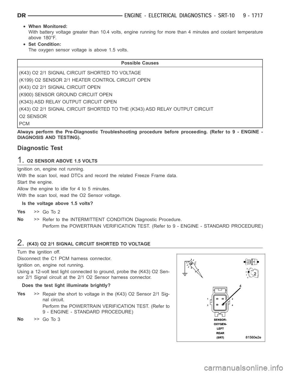
Using a 12-volt test light connected to ground, probe the (K43) O2 Sen-
sor 2/1 Signal circuit at the 2/1 O2 Sensor harness connector.
Does the test light illuminate brightly?
Ye s>>
Repair the short to voltage in the (K43) O2 Sensor 2/1 Sig-
nal circuit.
Perform the POWERTRAIN VERIFICATION TEST. (Refer to
9 - ENGINE - STANDARD PROCEDURE)
No>>
Go To 3