2006 DODGE RAM SRT-10 oil
[x] Cancel search: oilPage 113 of 5267

For a complete wiring diagramRefer to Section 8W.
Theory of Operation
When all criteria has been met, power is supplied to each MDS Solenoid when the engine is making a transition
from 8 cylinder mode to 4 cylinder mode. By actuating the solenoid, oil pressure is raised to the pair of lifters that
coincide with each particular solenoid. The oil pressure pushes in the locking pins that allows the lifter to collapse,
decoupling the valves and camshaft.
When Monitored:
Transition from 8 to 4 cylinder mode.
Set Condition:
The MDS fails to active and take place for cylinder 7. One trip fault.
Possible Causes
(K454) MDS SOLENOID NO.7 CONTROL SHORT TO GROUND
(K454) MDS SOLENOID NO.7 CONTROL OPEN
(Z42) GROUND CIRCUIT OPEN
INSUFFICIENT OIL PRESSURE ACTING ON THE LIFTER LOCKING PINS
OIL PASSAGES RESTRICTED
LIFTER
MDS SOLENOID NO.7
PCM
Always perform the Pre-Diagnostic Troubleshooting procedure before proceeding. (Refer to 9 - ENGINE -
DIAGNOSIS AND TESTING).
Diagnostic Test
1.ACTIVE DTC
Ignition on, engine not running.
With a scan tool, read DTCs.
Is the DTC active at this time?
Ye s>>
Go To 2
No>>
Refer to the INTERMITTENT CONDITION Diagnostic Procedure.
Perform the POWERTRAIN VERIFICATION TEST. (Refer to 9 - ENGINE - STANDARD PROCEDURE)
2.MDS SOLENOID NO.7
Turn the ignition off.
Gain access to the MDS Solenoid No.7.
Disconnect the MDS Solenoid No.7 harness connector.
Ignition on, engine not running.
Turn off all accessories.
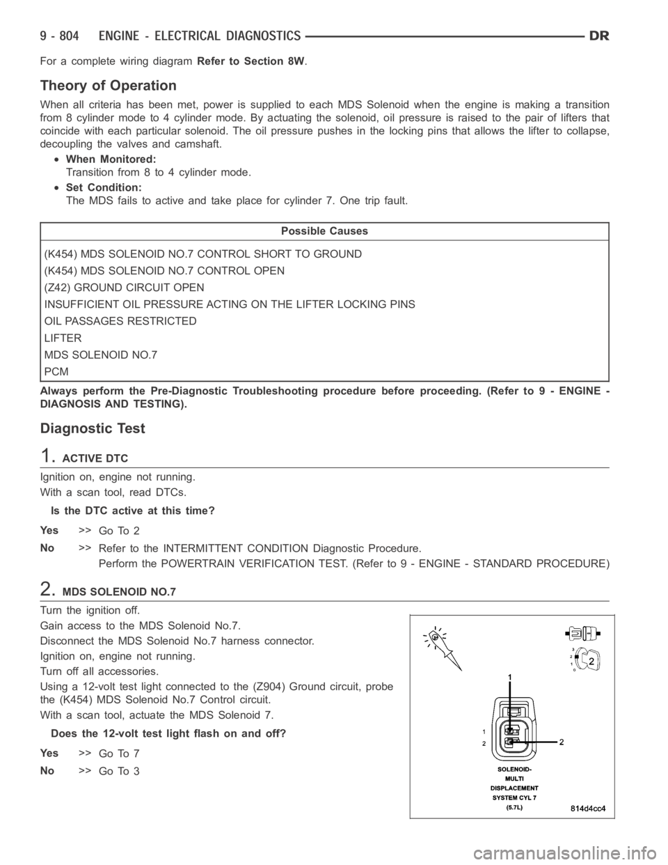
Using a 12-volt test light connected to the (Z904) Ground circuit, probe
the (K454) MDS Solenoid No.7 Control circuit.
With a scan tool, actuate the MDS Solenoid 7.
Does the 12-volt test light flash on and off?
Ye s>>
Go To 7
No>>
Go To 3
Page 116 of 5267

7.MDS SOLENOID 7
Turn the ignition off.
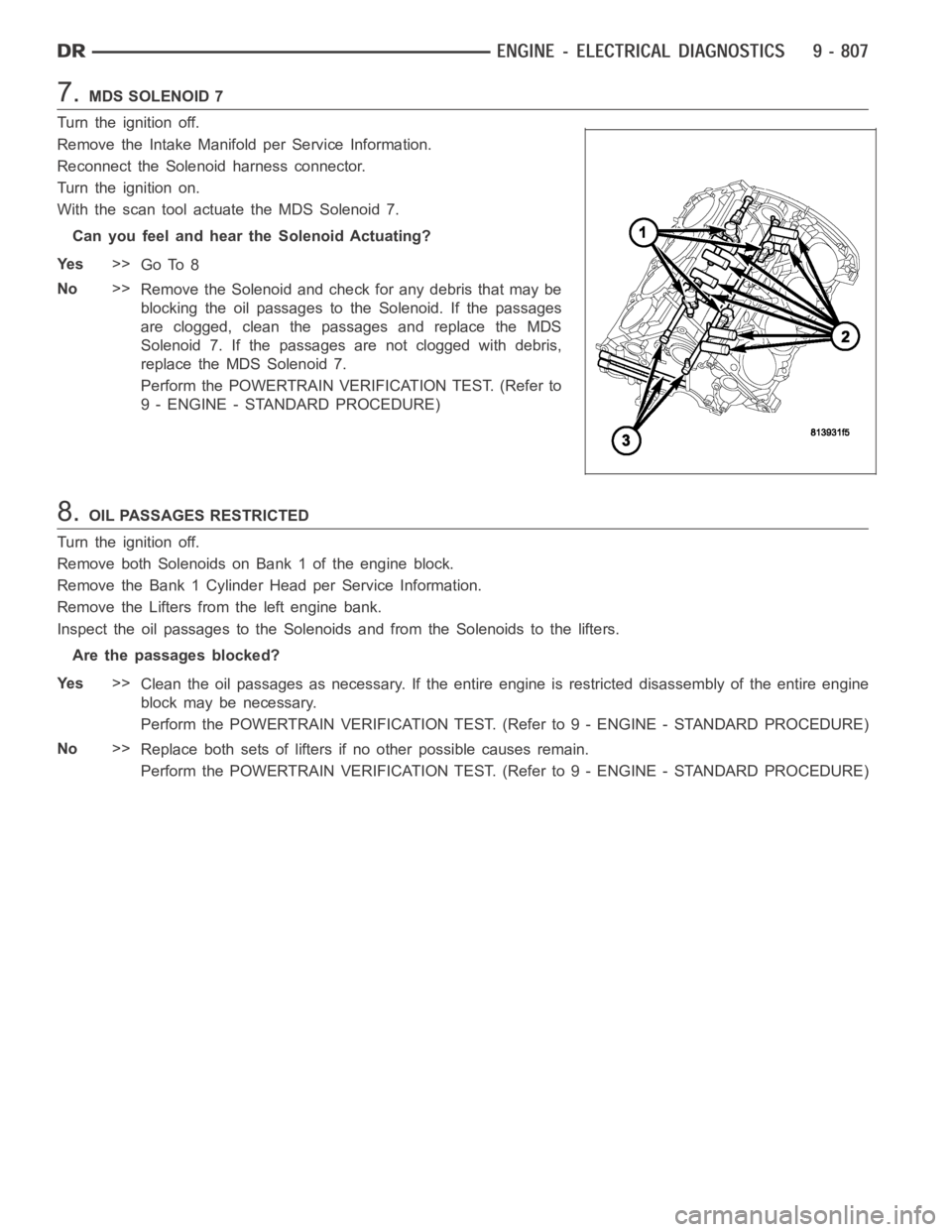
Remove the Intake Manifold per Service Information.
Reconnect the Solenoid harness connector.
Turn the ignition on.
With the scan tool actuate the MDS Solenoid 7.
Can you feel and hear the Solenoid Actuating?
Ye s>>
Go To 8
No>>
Remove the Solenoid and check for any debris that may be
blocking the oil passages to the Solenoid. If the passages
are clogged, clean the passages and replace the MDS
Solenoid 7. If the passages are not clogged with debris,
replace the MDS Solenoid 7.
Perform the POWERTRAIN VERIFICATION TEST. (Refer to
9 - ENGINE - STANDARD PROCEDURE)
8.OIL PASSAGES RESTRICTED
Turn the ignition off.
Remove both Solenoids on Bank 1 of the engine block.
Remove the Bank 1 Cylinder Head per Service Information.
Remove the Lifters from the left engine bank.
Inspect the oil passages to the Solenoids and from the Solenoids to the lifters.
Are the passages blocked?
Ye s>>
Clean the oil passages as necessary. If the entire engine is restricted disassembly of the entire engine
block may be necessary.
Perform the POWERTRAIN VERIFICATION TEST. (Refer to 9 - ENGINE - STANDARD PROCEDURE)
No>>
Replace both sets of lifters if no other possible causes remain.
Perform the POWERTRAIN VERIFICATION TEST. (Refer to 9 - ENGINE - STANDARD PROCEDURE)
Page 123 of 5267

P1521–INCORRECT ENGINE OIL TYPE
When Monitored:
Engine Running.
Set Condition:
Using the oil pressure, oil temperature and other vital engine inputs the PCM can determine the engine oil
viscosity. Incorrect viscosity will effect the operation of the MDS by delaying cylinder activation.
Possible Causes
INCORRECT ENGINE OIL TYPE
ENGINE OIL CONTAMINATION
ENGINE OIL
Always perform the Pre-Diagnostic Troubleshooting procedure before proceeding. (Refer to 9 - ENGINE -
DIAGNOSIS AND TESTING).
Diagnostic Test
1.ACTIVE DTC
NOTE: Review the customers oil change history. Make sure the customers is using the correct engine oil
viscosity. If the incorrect oil is being used, change the oil, using the correct engine oil viscosity.
Ignition on, engine off.
With the scan tool, read DTCs.
Is the DTC active at this time?
Ye s>>
Go to 2
No>>
Te s t C o m p l e t e .
2.ENGINE OIL
NOTE: If any engine oil pressure or oil temperature DTCs set along with P1521, repair them before continu-
ing with the P1521 diagnostics.
The following conditions must be checked.
OEM recommended oil viscosity is being used.
Customer is following the oil change schedule.
Check the engine oil for contamination. (i.e., fuel and/or engine coolant)
Internal engine condition that may effect oil pressure.
Were any of the above condition found?
Ye s>>
Repair as necessary.
Perform the POWERTRAIN VERIFICATION TEST. (Refer to 9 - ENGINE - STANDARD PROCEDURE)
No>>
Change the engine oil using the correct oil viscosity.
Perform the POWERTRAIN VERIFICATION TEST. (Refer to 9 - ENGINE - STANDARD PROCEDURE)
Page 175 of 5267

When Monitored:
With the engine running in closed loop mode, the ambient/battery temperature above (-7°C) 20°F, altitude
below 8500 ft.
Set Condition:
If the PCM multiplies short term compensation by long term adaptive as wellas a purge fuel multiplier and the
result is below a certain value for 30 seconds over two trips, a freeze frameis stored, the MIL illuminates and
a trouble code is stored. Two Trip Fault. Three good trips to turn off the MIL.
Possible Causes
EXHAUST LEAK
ENGINE MECHANICAL
1/2O2SENSOR
(K141) O2 SENSOR 1/2 SIGNAL CIRCUIT
(K299) O2 1/2 HEATER CONTROL CIRCUIT
(K904) O2 RETURN DOWNSTREAM CIRCUIT
FUEL CONTAMINATION
Always perform the Pre-Diagnostic Troubleshooting procedure before proceeding. (Refer to 9 - ENGINE -
DIAGNOSIS AND TESTING).
Diagnostic Test
1.ACTIVE DTC
NOTE: Check the vehicle repair history. If the 1/2 O2 has been replaced makesure that the O2 sensor was
properly installed and meets OEM specification.
NOTE: Check for contaminants that may have damaged the O2 Sensor: contaminated fuel, unapproved sil-
icone, oil and coolant.
Ignition on, engine not running.
With a scan tool, read DTCs.
Is the DTC active at this time?
Ye s>>
Go To 2
No>>
Refer to the INTERMITTENT CONDITION Diagnostic Procedure.
Perform the POWERTRAIN VERIFICATION TEST. (Refer to 9 - ENGINE - STANDARD PROCEDURE)
2.EXHAUST LEAK
Turn the ignition off.
WARNING: To avoid personal injury from the exhaust system being hot, allowthe exhaust to cool down to
a safe temperature before performing a physical inspection. Failure to follow these instructions can result in
personal injury or death.
Visually and Physically inspect the exhaust system for holes, cracks and blockage in the exhaust system.
Is the exhaust system is good condition?
Ye s>>
Go To 3
No>>
Repair or Replace as necessary.
Perform the POWERTRAIN VERIFICATION TEST. (Refer to 9 - ENGINE - STANDARD PROCEDURE)
Page 180 of 5267

When Monitored:
With the engine running in closed loop mode, the ambient/battery temperature above (-7°C) 20°F, altitude
below 8500 ft.
Set Condition:
If the PCM multiplies short term compensation by long term adaptive as wellas a purge fuel multiplier and the
result is below a certain value for 30 seconds over two trips, a freeze frameis stored, the MIL illuminates and
a trouble code is stored. Two Trip Fault. Three good trips to turn off the MIL.
Possible Causes
EXHAUST LEAK
ENGINE MECHANICAL
1/2O2SENSOR
(K141) O2 SENSOR 1/2 SIGNAL CIRCUIT
(K299) O2 HEATER 1/2 CONTROL CIRCUIT
(K904) O2 RETURN DOWNSTREAM CIRCUIT
FUEL CONTAMINATION
Always perform the Pre-Diagnostic Troubleshooting procedure before proceeding. (Refer to 9 - ENGINE -
DIAGNOSIS AND TESTING).
Diagnostic Test
1.ACTIVE DTC
NOTE: Check the vehicle repair history. If the 1/2 O2 has been replaced makesure that the O2 sensor was
properly installed and meets OEM specification.
NOTE: Check for contaminants that may have damaged the O2 Sensor: contaminated fuel, unapproved sil-
icone, oil and coolant.
Ignition on, engine not running.
With a scan tool, read DTCs.
Is the DTC active at this time?
Ye s>>
Go To 2
No>>
Refer to the INTERMITTENT CONDITION Diagnostic Procedure.
Perform the POWERTRAIN VERIFICATION TEST. (Refer to 9 - ENGINE - STANDARD PROCEDURE)
2.EXHAUST LEAK
Turn the ignition off.
WARNING: To avoid personal injury from the exhaust system being hot, allowthe exhaust to cool down to
a safe temperature before performing a physical inspection. Failure to follow these instructions can result in
personal injury or death.
Visually and Physically inspect the exhaust system for holes, cracks and blockage in the exhaust system.
Is the exhaust system is good condition?
Ye s>>
Go To 3
No>>
Repair or Replace as necessary.
Perform the POWERTRAIN VERIFICATION TEST. (Refer to 9 - ENGINE - STANDARD PROCEDURE)
Page 186 of 5267

When Monitored:
With the engine running in closed loop mode, the ambient/battery temperature above (-7°C) 20°F, altitude
below 8500 ft and fuel level greater than 15%.
Set Condition:
If the PCM multiplies short term compensation by long term adaptive and a certain percentage is exceeded for
two trips, a freeze frame is stored, the MIL illuminates and a trouble code is stored. Two Trip Fault. Three good
trips to turn off the MIL.
Possible Causes
EXHAUST LEAK
ENGINE MECHANICAL
2/2O2SENSOR
(K243) O2 2/2 SIGNAL CIRCUIT
(K399) O2 HEATER 2/2 CONTROL CIRCUIT
(K904) O2 RETURN DOWNSTREAM CIRCUIT
FUEL CONTAMINATION
Always perform the Pre-Diagnostic Troubleshooting procedure before proceeding. (Refer to 9 - ENGINE -
DIAGNOSIS AND TESTING).
Diagnostic Test
1.ACTIVE DTC
NOTE: Check the vehicle repair history. If the 2/2 O2 has been replaced makesure that the O2 sensor was
properly installed and meets OEM specification.
NOTE: Check for contaminants that may have damaged the O2 Sensor: contaminated fuel, unapproved sil-
icone, oil and coolant.
Ignition on, engine not running.
With a scan tool, read DTCs.
Is the DTC active at this time?
Ye s>>
Go To 2
No>>
Refer to the INTERMITTENT CONDITION Diagnostic Procedure.
Perform the POWERTRAIN VERIFICATION TEST. (Refer to 9 - ENGINE - STANDARD PROCEDURE)
2.EXHAUST LEAK
Turn the ignition off.
WARNING: To avoid personal injury from the exhaust system being hot, allowthe exhaust to cool down to
a safe temperature before performing a physical inspection. Failure to follow these instructions can result in
personal injury or death.
Visually and Physically inspect the exhaust system for holes, cracks and blockage in the exhaust system.
Is the exhaust system is good condition?
Ye s>>
Go To 3
No>>
Repair or Replace as necessary.
Perform the POWERTRAIN VERIFICATION TEST. (Refer to 9 - ENGINE - STANDARD PROCEDURE)
Page 191 of 5267

When Monitored:
With the engine running in closed loop mode, the ambient/battery temperature above (-7°C) 20°F, altitude
below 8500 ft.
Set Condition:
If the PCM multiplies short term compensation by long term adaptive as wellas a purge fuel multiplier and the
result is below a certain value for 30 seconds over two trips, a freeze frameis stored, the MIL illuminates and
a trouble code is stored. Two Trip Fault. Three good trips to turn off the MIL.
Possible Causes
EXHAUST LEAK
ENGINE MECHANICAL
2/2O2SENSOR
(K342) O2 SENSOR 2/2 SIGNAL CIRCUIT
(K399) O2 SENSOR 2/2 HEATER CONTROL CIRCUIT
(K904) O2 RETURN DOWNSTREAM CIRCUIT
FUEL CONTAMINATION
Always perform the Pre-Diagnostic Troubleshooting procedure before proceeding. (Refer to 9 - ENGINE -
DIAGNOSIS AND TESTING).
Diagnostic Test
1.ACTIVE DTC
NOTE: Check the vehicle repair history. If the 2/2 O2 has been replaced makesure that the O2 sensor was
properly installed and meets OEM specification.
NOTE: Check for contaminants that may have damaged the O2 Sensor: contaminated fuel, unapproved sil-
icone, oil and coolant.
Ignition on, engine not running.
With a scan tool, read DTCs.
Is the DTC active at this time?
Ye s>>
Go To 2
No>>
Refer to the INTERMITTENT CONDITION Diagnostic Procedure.
Perform the POWERTRAIN VERIFICATION TEST. (Refer to 9 - ENGINE - STANDARD PROCEDURE)
2.EXHAUST LEAK
Turn the ignition off.
WARNING: To avoid personal injury from the exhaust system being hot, allowthe exhaust to cool down to
a safe temperature before performing a physical inspection. Failure to follow these instructions can result in
personal injury or death.
Visually and Physically inspect the exhaust system for holes, cracks and blockage in the exhaust system.
Is the exhaust system is good condition?
Ye s>>
Go To 3
No>>
Repair or Replace as necessary.
Perform the POWERTRAIN VERIFICATION TEST. (Refer to 9 - ENGINE - STANDARD PROCEDURE)
Page 318 of 5267

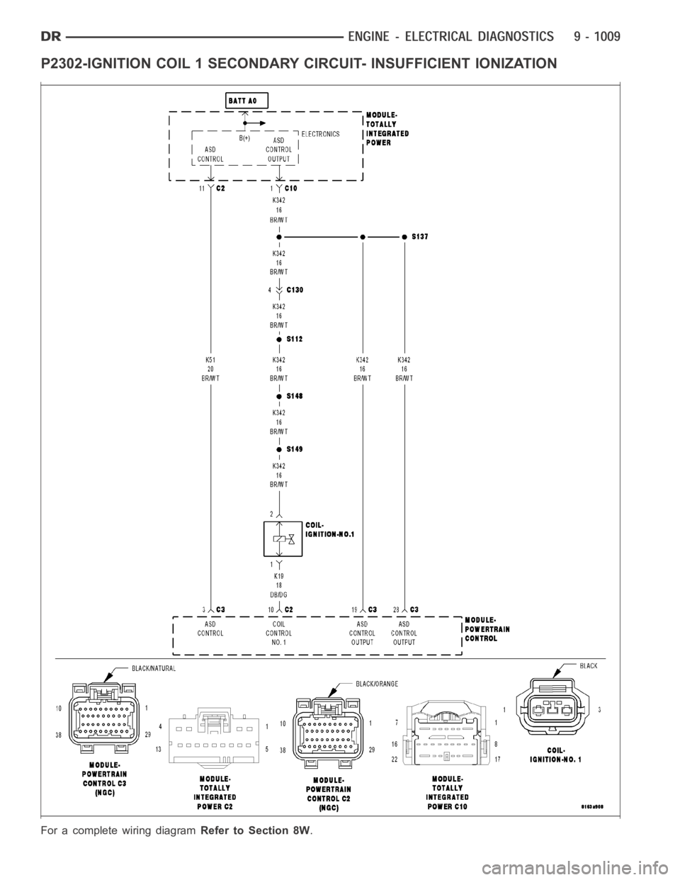
P2302-IGNITION COIL 1 SECONDARY CIRCUIT- INSUFFICIENT IONIZATION
For a complete wiring diagramRefer to Section 8W.