2006 DODGE RAM SRT-10 fuse diagram
[x] Cancel search: fuse diagramPage 657 of 5267

P0477-LOW VOLTAGE ON THE ENGINE BRAKE DRIVER
For a complete wiring diagramRefer to Section 8W.
When Monitored:
When the ignition is on.
Set Condition:
When the signal from the engine brake driver output does not match the signal from the engine brake driver
feedback.
Possible Causes
WIRING HARNESS
ENGINE BRAKE DRIVER RELAY
FUSED B+ OPEN
ENGINE BRAKE DRIVER SIGNAL CIRCUIT OPEN
INTERMITTENT CONDITION
ENGINE BRAKE DRIVER SIGNAL CIRCUIT SHORTED TO BATTERY NEGATIVE
ECM
Always perform the Pre-Diagnostic Troubleshooting procedure before proceeding. (Refer to 9 - ENGINE -
DIAGNOSIS AND TESTING)
Diagnostic Test
1.RELAY CLICKING
Turn the engine off (ignition on).
With the scan tool, actuate the exhaust brake relay.
Can you hear the Relay clicking?
Ye s>>
Go To 2
No>>
Go To 3
2.WIRING HARNESS
With the scan tool, actuate the exhaust brake relay.
While the relay is clicking, wiggle the wiring harness and connectors throughout the circuit.
Does this interrupt the clicking?
Ye s>>
Repair or replace the wiring harness.
Perform POWERTRAIN VERIFICATION TEST VER - 1 (DIESEL). (Refer to 8 - ELECTRICAL/ELEC-
TRONIC CONTROL MODULES/ENGINE CONTROL MODULE - DIAGNOSIS AND TESTING)
No>>
Go To 3
3.Engine Brake Driver Relay
Remove the Engine Brake Driver Relay.
Check connectors - Clean/repair as necessary.
Measure the resistance between terminals 86 and 85 of the engine brake relay.
Is the resistance less than 100 Ohms?
Ye s>>
Go To 4
No>>
Replace the Engine Brake Driver Relay.
Perform POWERTRAIN VERIFICATION TEST VER - 1 (DIESEL). (Refer to 8 - ELECTRICAL/ELEC-
TRONIC CONTROL MODULES/ENGINE CONTROL MODULE - DIAGNOSIS AND TESTING)
Page 882 of 5267
*CHECKING THE ECM POWER AND GROUNDS
For a complete wiring diagramRefer to Section 8W.
Possible Causes
ECM GROUND CIRCUIT(S) OPEN
FUSED B+ CIRCUIT OPEN
FUSED IGNITION SWITCH OUTPUT CIRCUIT OPEN
Diagnostic Test
1.ECM GROUND CIRCUIT(S) OPEN
Turn the ignition off.
Disconnect the ECM harness connectors.
Using a 12-volt test light connected to 12-volts, check each of the ECM ground circuits in ECM harness connector.
Did the test light illuminate for each cavity?
Ye s>>
Go To 2
No>>
Repair the ECM Ground circuit(s) for an open.
Perform POWERTRAIN VERIFICATION TEST VER - 1 (DIESEL). (Refer to 8 - ELECTRICAL/ELEC-
TRONIC CONTROL MODULES/ENGINE CONTROL MODULE - DIAGNOSIS AND TESTING)
2.FUSED IGNITION SWITCH OUTPUT CIRCUIT OPEN
Turn the ignition off.
Disconnect the ECM harness connectors.
Turn the ignition on.
Using a 12-volt test light connected to ground, check the Fused Ignition Switch Output circuit in ECM harness con-
nector.
Is the test light on?
Ye s>>
Go To 3
No>>
Repair the Fused Ignition Switch Output circuit for an open.
Perform POWERTRAIN VERIFICATION TEST VER - 1 (DIESEL). (Refer to 8 - ELECTRICAL/ELEC-
TRONIC CONTROL MODULES/ENGINE CONTROL MODULE - DIAGNOSIS AND TESTING)
3.FUSED B+ CIRCUIT OPEN
Turn the ignition off.
Disconnect the ECM harness connectors.
Using a 12-volt test light connected to ground, check each Fused B+ circuitin the ECM harness connector.
Does the test light illuminatebrightly for each circuit?
Ye s>>
Te s t C o m p l e t e .
Perform POWERTRAIN VERIFICATION TEST VER - 1 (DIESEL). (Refer to 8 - ELECTRICAL/ELEC-
TRONIC CONTROL MODULES/ENGINE CONTROL MODULE - DIAGNOSIS AND TESTING)
No>>
Repair the Fused B+ Output circuit for an open.
Perform POWERTRAIN VERIFICATION TEST VER - 1 (DIESEL). (Refer to 8 - ELECTRICAL/ELEC-
TRONIC CONTROL MODULES/ENGINE CONTROL MODULE - DIAGNOSIS AND TESTING)
Page 1460 of 5267
P1696-PCM FAILURE EEPROM WRITE DENIED
For a complete wiring diagramRefer to Section 8W.
When Monitored:
Ignition on and battery voltage greater than 10 volts.
Set Condition:
An attempt to program/write to the internal EEPROM failed, also checks at powerdown.
Possible Causes
SRI MILEAGE INVALID
PCM
Always perform the Pre-Diagnostic Troubleshooting procedure before proceeding. (Refer to 9 - ENGINE -
DIAGNOSIS AND TESTING)
Diagnostic Test
1.SCAN TOOL DISPLAYS WRITE FAILURE
Ignition on, engine not running.
With the scan tool, perform the SRI Memory Test.
Does the scan tool display Write Failure?
Ye s>>
Replace and program the Powertrain Control Module per Service Information.
Perform the POWERTRAIN VERIFICATION TEST. (Refer to 9 - ENGINE - STANDARD PROCEDURE)
No>>
Go To 2
2.SCAN TOOL DISPLAYS WRITE REFUSED
With the scan tool, perform the SRI Memory Test.
Does the scan tool display Write Refused?
Ye s>>
Go To 3
No>>
Go To 4
3.PCM REFUSED 2ND TEST
With the scan tool, perform the SRI Memory Test a second time.
NOTE: Retest the SRI Memory two more times.
Does the scan tool display Write Refused again?
Ye s>>
Replace and program the Powertrain Control Module per Service Information.
Perform the POWERTRAIN VERIFICATION TEST. (Refer to 9 - ENGINE - STANDARD PROCEDURE)
No>>
Te s t C o m p l e t e .
4.SCAN TOOL DISPLAYS SRI MILEAGE INVALID
With the scan tool, perform the SRI Memory Test.
Does the scan tool display SRI Mileage Invalid?
Ye s>>
Update the mileage and retest the SRI Memory.
Perform the POWERTRAIN VERIFICATION TEST. (Refer to 9 - ENGINE - STANDARD PROCEDURE)
No>>
Go To 5
Page 2845 of 5267
P0884-POWER UP AT SPEED
For a complete wiring diagramRefer to Section 8W.
When Monitored:
One time after each controller reset. Note: the Transmission Control Module is integrated with Powertrain Con-
trol Module. The Transmission Control Module has separate powers and grounds specifically to its portion of
the PCM.
Set Condition:
This DTC will set if the PCM powers up and senses the vehicle in a valid forward gear (no PRNDL DTCs) with
a output speed above 800 RPM, approximately 32 Kmh or 20 mph.
Possible Causes
INTERMITTENT POWER AND GROUND CIRCUITS
Always perform the 42RLE Pre-Diagnostic Troubleshooting procedure before proceeding. (Refer to 21 -
TRANSMISSION/TRANSAXLE/AUTOMATIC - 42RLE - STANDARD PROCEDURE)
Theory of Operation
If a vehicle loses power to the PCM, the vehicle will go to the 2nd gear mode since there is no power available to
control the transmission solenoids. However if power is restored, the PCMwill power-up and normal operation will
be restored. This DTC identifies that power to the PCM was restored when thegear selector was in a
Driveposi-
tion while the vehicle was moving at speeds above 32 Kmh (20 mph). If a customer shifts to Neutral and cycles the
ignition key and quickly shifts to
Drivewhile moving before the PCM comes out of its START ROUTINE, the DTC
can be set. Therefore it is critical that this DTC diagnosis repair procedure should only be used if the vehicle is
experiencing intermittent 2nd gear operation and subsequently a return to normal operation during normal driving.
The transmission will not be placed in Limp-in. This is an informational DTC to be used when attempting to diag-
nose an intermittent 2nd gear operation and subsequent return to normal transmission operation.
Diagnostic Test
1.CHECK THE POWER AND GROUND CIRCUITS
This DTC is set when the PCM is initialized while the vehicle is moving in a valid forward gear. This is usually
caused by a momentary loss of power to the Transmission portion of the PCM.
CAUTION: Do not probe the PCM harness connectors. Probing the PCM harness connectors will damage
the PCM terminals resulting in poor terminal to pin connection. Install Miller tool #8815 to perform diagno-
sis.
NOTE: Due to the integration of the Powertrain and Transmission Control Modules, the transmission part of
the PCM has its own specific power and ground circuits.
Check all of the Fused B(+), Fused Ignition Switch Output, and Ground circuits related to the PCM for an intermit-
tent open or short to ground.
Perform a wiggle test on all wiring and connectors pertaining to the PCM while looking for shorted or open circuits.
With the scan tool, check the DTC EVENT DATA to help identify the conditionsin which the DTC was set.
If there are no possible causes remaining, view repair.
Repair
Repair as necessary.
Perform 42RLE TRANSMISSION VERIFICATION TEST - VER 1. (Refer to 21 - TRANSMISSION/
TRANSAXLE/AUTOMATIC - 42RLE - STANDARD PROCEDURE)
Page 3271 of 5267
When Monitored:
When Powertrain Control Module initially powers up. Due to the integration of the Powertrain and Transmission
Control Modules, the transmission part of the PCM has its own specific power and ground circuits.
Set Condition:
This DTC will set if the PCM powers up and senses the vehicle in a valid forwardgear,withnoPRNDLDTCs,
and an output speed above 800 RPM, approximately 32 Kmh or 20 mph.
Possible Causes
POWER UP AT SPEED
Always perform the 45RFE/545RFE Pre-Diagnostic Troubleshooting Procedure before proceeding. (Refer to
21 - TRANSMISSION/TRANSAXLE/AUTOMATIC - 45RFE/545RFE - STANDARD PROCEDURE)
Theory of Operation
If a vehicle loses power to the Transmission Control System, the solenoids(LR, 2C, OD, UD, 4C) will go to their
respective power off state. Some solenoids are normally vented and some are normally applied in their power off
state. The transmission is designed to be in 3rd gear with all of the solenoids in this state. However, if power is
restored, the Transmission Control System will power-up and normal operation will be restored.
This code identifies that power to the Transmission Control System was restored when the gear selector was in a
Driveposition while the vehicle was moving at speeds above 32 Kmh (20 mph).This DTC does not indicate a
problem with the transmission or Transmission Control System,instead, it suggests intermittent problems in
the fused ignition switch output, fused B(+), or ground circuits to the TCM. Alternately, if a person performs a rolling
restart maneuver, the DTC can be set. Therefore it is critical that this DTCbe investigated if the vehicle is experi-
encing intermittent 3rd gear operation and a subsequent return to normal operation.
Diagnostic Test
1.CHECK THE POWER AND GROUND CIRCUITS
This DTC is set when the Transmission portion of the Powertrain Control Module is initialized while the vehicle is
movingdowntheroadinavalidforwardgear.
Using the wiring diagram/schematic as a guide, inspect the wiring and connectors.
NOTE: Due to the integration of the Powertrain and Transmission Control Modules, the transmission part of
the PCM has its own specific power and ground circuits.
Check all of the Fused B(+), Fused Ignition Switch Output, and ground circuits to the PCM for an intermittent open
or short to ground.
With the scan tool, check the DTC EVENT DATA to help identify the conditionsin which the DTC was set.
View repair.
Repair
Check all power and ground circuits to the PCM and repair as necessary.
Perform 45RFE/545RFE TRANSMISSION VERIFICATION TEST - VER 1. (Refer to 21- TRANSMIS-
SION/TRANSAXLE/AUTOMATIC - 45RFE/545RFE - STANDARD PROCEDURE)
Page 3318 of 5267
P1684-BATTERY WAS DISCONNECTED
For a complete wiring diagramRefer to Section 8W.
When Monitored:
Whenever the ignition is in the Run/Start position.
Set Condition:
This DTC will set whenever Powertrain Control Module is disconnected fromFused B(+) or ground. It will also
be set using the scan tool to perform a Battery Disconnect and/or Quick Learn procedure.
Possible Causes
BATTERY WAS DISCONNECTED
SCAN TOOL BATTERY DISCONNECT PERFORMED
PCM WAS REPLACED OR DISCONNECTED
QUICK LEARN WAS PERFORMED
Always perform the 45RFE/545RFE Pre-Diagnostic Troubleshooting Procedure before proceeding. (Refer to
21 - TRANSMISSION/TRANSAXLE/AUTOMATIC - 45RFE/545RFE - STANDARD PROCEDURE)
Theory of Operation
The PCM uses a battery backed RAM (Random Access Memory) is used to maintainsome learned values. When
the battery B(+) is disconnected, the memory is lost. When the B(+) is restored, this memory loss is detected by the
Transmission Control System. The DTC is set and the learned values are initialized to known constants or previ-
ously learned values from EEPROM (Electronic Erasable Programmable ReadOnly Memory). This results in the
reinitialization of some parameters.
Diagnostic Test
1.POSSIBLE CAUSES
This DTC is an informational DTC only.
This DTC is set due to a momentary loss of power and/or the ground circuits tothe PCM.
Below are a list of possible causes associated with this DTC.
Battery was disconnected.
The BATTERY DISCONNECT feature on the scan tool was performed.
The QUICK LEARN feature on the scan tool was performed.
PCM was replaced or disconnected.
Were any of the above possible causes performed?
Ye s>>
This is the cause of the DTC. Erase the DTC and return vehicle to customer.
Perform 45RFE/545RFE TRANSMISSION VERIFICATION TEST - VER 1. (Refer to 21- TRANSMIS-
SION/TRANSAXLE/AUTOMATIC - 45RFE/545RFE - STANDARD PROCEDURE)
No>>
Go To 2
Page 4046 of 5267
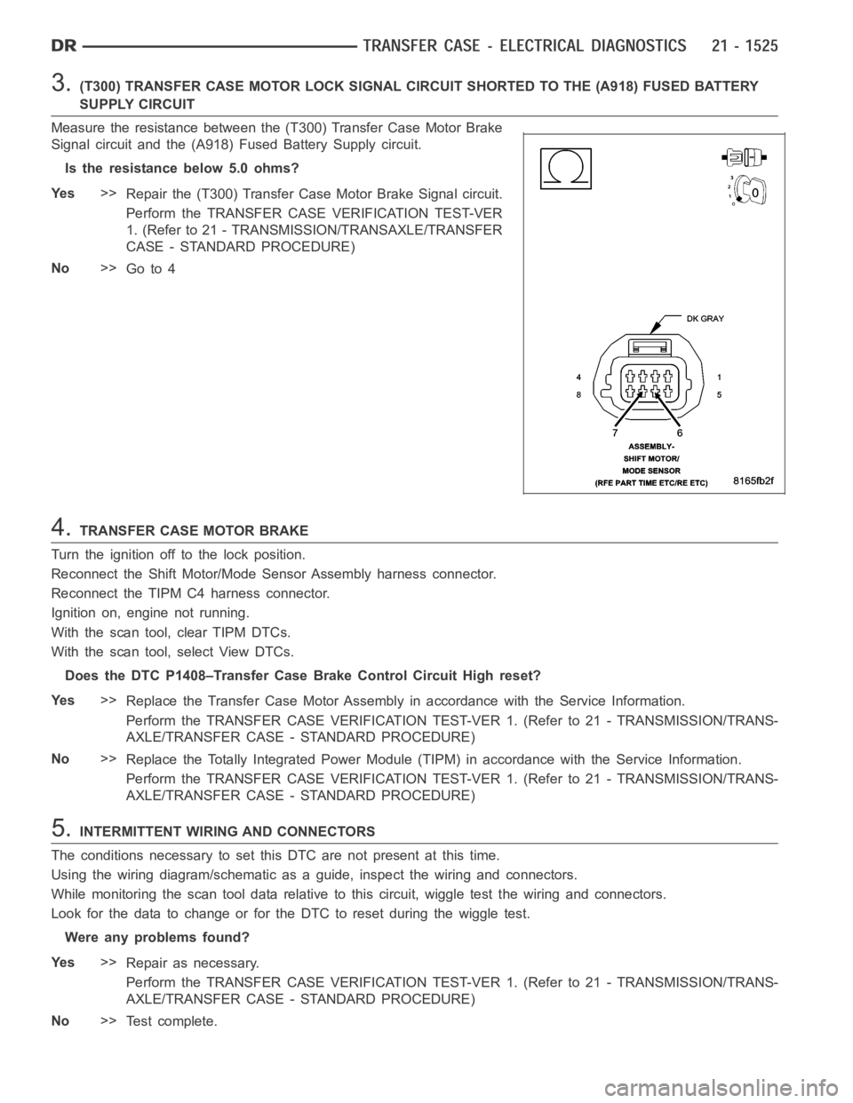
3.(T300) TRANSFER CASE MOTOR LOCK SIGNAL CIRCUIT SHORTED TO THE (A918) FUSEDBATTERY
SUPPLY CIRCUIT
Measure the resistance between the (T300) Transfer Case Motor Brake
Signal circuit and the (A918) Fused Battery Supply circuit.
Is the resistance below 5.0 ohms?
Ye s>>
Repair the (T300) Transfer Case Motor Brake Signal circuit.
Perform the TRANSFER CASE VERIFICATION TEST-VER
1. (Refer to 21 - TRANSMISSION/TRANSAXLE/TRANSFER
CASE - STANDARD PROCEDURE)
No>>
Go to 4
4.TRANSFER CASE MOTOR BRAKE
Turn the ignition off to the lock position.
Reconnect the Shift Motor/Mode Sensor Assembly harness connector.
Reconnect the TIPM C4 harness connector.
Ignition on, engine not running.
With the scan tool, clear TIPM DTCs.
With the scan tool, select View DTCs.
Does the DTC P1408–Transfer Case Brake Control Circuit High reset?
Ye s>>
Replace the Transfer Case Motor Assembly in accordance with the Service Information.
Perform the TRANSFER CASE VERIFICATION TEST-VER 1. (Refer to 21 - TRANSMISSION/TRANS-
AXLE/TRANSFER CASE - STANDARD PROCEDURE)
No>>
Replace the Totally Integrated Power Module (TIPM) in accordance with theService Information.
Perform the TRANSFER CASE VERIFICATION TEST-VER 1. (Refer to 21 - TRANSMISSION/TRANS-
AXLE/TRANSFER CASE - STANDARD PROCEDURE)
5.INTERMITTENT WIRING AND CONNECTORS
The conditions necessary to set this DTC are not present at this time.
Using the wiring diagram/schematic as a guide, inspect the wiring and connectors.
While monitoring the scan tool data relative to this circuit, wiggle test the wiring and connectors.
Look for the data to change or for the DTC to reset during the wiggle test.
Were any problems found?
Ye s>>
Repair as necessary.
Perform the TRANSFER CASE VERIFICATION TEST-VER 1. (Refer to 21 - TRANSMISSION/TRANS-
AXLE/TRANSFER CASE - STANDARD PROCEDURE)
No>>
Te s t c o m p l e t e .