2006 DODGE RAM SRT-10 ignition
[x] Cancel search: ignitionPage 3604 of 5267
3.COMPARE SCAN TOOL GOVERNOR PRESSURE READING TO PRESSURE GAUGE READING
Turn the ignition off to the lock position.
Connect a 700 kPa (100 psi) Pressure Gauge to the Governor Pressure test port. (Refer to 21 - TRANSMISSION/
TRANSAXLE/AUTOMATIC - 48RE - DIAGNOSIS AND TESTING)
Start the engine and allow the engine to idle.
Warm the transmission to a normal operating temperature above 43° C (110° F).
With the scan tool, read the Governor Pressure and compare the scan tool Governor Pressure reading to the Pres-
sure Gauge reading.
Does the scan tool Governor Pressure reading match the Pressure Gauge reading within 6.9 kPa (1
psi)?
Ye s>>
Go To 4
No>>
Go To 7
4.TRANSMISSION - INTERNAL DAMAGE
Turn the ignition off to the lock position.
Remove the transmission oil pan per the Service Information. (Refer to 21 -TRANSMISSION/TRANSAXLE/AUTO-
MATIC - 48RE/FLUID - STANDARD PROCEDURE)
Inspect the transmission oil pan for burnt oil and/or excessive debris.
Does the transmission contain burnt oil and/or excessive debris?
Ye s>>
Repair internal transmission as necessary. (Refer to 21 - TRANSMISSION/TRANSAXLE/AUTOMATIC -
48RE - REMOVAL)
Perform RE TRANSMISSION VERIFICATION TEST VER - 1 (GAS). (Refer to 21 - TRANSMISSION/
TRANSAXLE/AUTOMATIC - 48RE - STANDARD PROCEDURE)
No>>
Go To 5
5.CHECK INTERNAL TRANSMISSION FOR A FLUID LEAK
Inspect the transmission for internal fluid leakage in the Valve Body or the Governor Pressure Solenoid. (Refer to 21
- TRANSMISSION/TRANSAXLE/AUTOMATIC - 48RE/VALVE BODY - REMOVAL)
Were there any problems found?
Ye s>>
Repair the internal transmission as necessary per the Service Information. (Refer to 21 - TRANSMIS-
SION/TRANSAXLE/AUTOMATIC - 48RE/VALVE BODY - REMOVAL)
Perform RE TRANSMISSION VERIFICATION TEST VER - 1 (GAS). (Refer to 21 - TRANSMISSION/
TRANSAXLE/AUTOMATIC - 48RE - STANDARD PROCEDURE)
No>>
Go To 6
6.VERIFY OPERATION - TEST DRIVE
Remove the pressure gauge from the transmission.
Install the transmission oil pan and refill the transmission per the Service Information. (Refer to 21 - TRANSMIS-
SION/TRANSAXLE/AUTOMATIC - 48RE/FLUID - STANDARD PROCEDURE)
With the scan tool, erase Engine DTCs.
Test drive the vehicle.
Be sure to stop the vehicle and move the gear selector into the park positionfor a minimum of 5 seconds at least
three times during the drive cycle.
With the scan tool, read Engine DTCs.
Did the DTC reset?
Ye s>>
Using the schematics as a guide, check the Powertrain Control Module (PCM)pins, terminals, and con-
nectors for corrosion, damage, or terminal push out. Pay particular attention to all power and ground
circuits. If no problems are found, replace and program the PCM per the Service Information. (Refer to
Page 3605 of 5267
8 - ELECTRICAL/ELECTRONIC CONTROL MODULES/POWERTRAIN CONTROL MODULE -
REMOVAL)
Perform RE TRANSMISSION VERIFICATION TEST VER - 1 (GAS). (Refer to 21 - TRANSMISSION/
TRANSAXLE/AUTOMATIC - 48RE - STANDARD PROCEDURE)
No>>
Go To 10
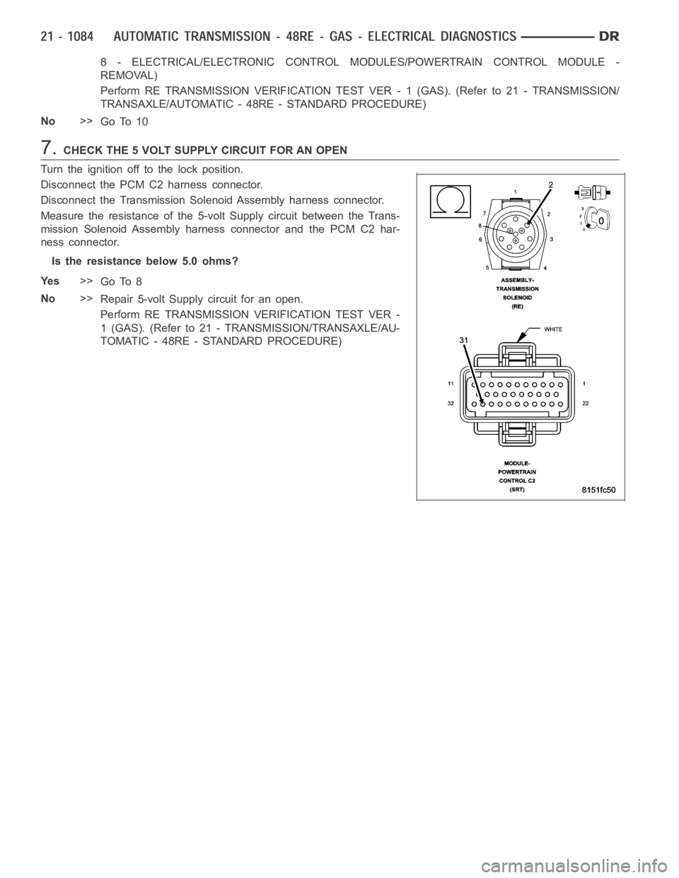
7.CHECK THE 5 VOLT SUPPLY CIRCUIT FOR AN OPEN
Turn the ignition off to the lock position.
Disconnect the PCM C2 harness connector.
Disconnect the Transmission Solenoid Assembly harness connector.
Measure the resistance of the 5-volt Supply circuit between the Trans-
mission Solenoid Assembly harness connector and the PCM C2 har-
ness connector.
Is the resistance below 5.0 ohms?
Ye s>>
Go To 8
No>>
Repair 5-volt Supply circuit for an open.
Perform RE TRANSMISSION VERIFICATION TEST VER -
1 (GAS). (Refer to 21 - TRANSMISSION/TRANSAXLE/AU-
TOMATIC - 48RE - STANDARD PROCEDURE)
Page 3606 of 5267
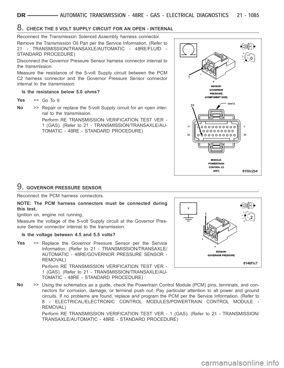
8.CHECK THE 5 VOLT SUPPLY CIRCUIT FOR AN OPEN - INTERNAL
Reconnect the Transmission Solenoid Assembly harness connector.
Remove the Transmission Oil Pan perthe Service Information. (Refer to
21 - TRANSMISSION/TRANSAXLE/AUTOMATIC - 48RE/FLUID -
STANDARD PROCEDURE)
Disconnect the Governor Pressure Sensor harness connector internal to
the transmission.
Measure the resistance of the 5-volt Supply circuit between the PCM
C2 harness connector and the Governor Pressure Sensor connector
internal to the transmission.
Is the resistance below 5.0 ohms?
Ye s>>
Go To 9
No>>
Repair or replace the 5-volt Supply circuit for an open inter-
nal to the transmission.
Perform RE TRANSMISSION VERIFICATION TEST VER -
1 (GAS). (Refer to 21 - TRANSMISSION/TRANSAXLE/AU-
TOMATIC - 48RE - STANDARD PROCEDURE)
9.GOVERNOR PRESSURE SENSOR
Reconnect the PCM harness connectors.
NOTE: The PCM harness connectors must be connected during
this test.
Ignition on, engine not running.
Measure the voltage of the 5-volt Supply circuit at the Governor Pres-
sure Sensor connector internal to the transmission.
Is the voltage between 4.5 and 5.5 volts?
Ye s>>
Replace the Governor Pressure Sensor per the Service
Information. (Refer to 21 - TRANSMISSION/TRANSAXLE/
AUTOMATIC - 48RE/GOVERNOR PRESSURE SENSOR -
REMOVAL)
Perform RE TRANSMISSION VERIFICATION TEST VER -
1 (GAS). (Refer to 21 - TRANSMISSION/TRANSAXLE/AU-
TOMATIC - 48RE - STANDARD PROCEDURE)
No>>
Using the schematics as a guide, check the Powertrain Control Module (PCM)pins, terminals, and con-
nectors for corrosion, damage, or terminal push out. Pay particular attention to all power and ground
circuits. If no problems are found, replace and program the PCM per the Service Information. (Refer to
8 - ELECTRICAL/ELECTRONIC CONTROL MODULES/POWERTRAIN CONTROL MODULE -
REMOVAL)
Perform RE TRANSMISSION VERIFICATION TEST VER - 1 (GAS). (Refer to 21 - TRANSMISSION/
TRANSAXLE/AUTOMATIC - 48RE - STANDARD PROCEDURE)
Page 3609 of 5267
Theory of Operation
The Governor Pressure Sensor is used by the PCM to adjust the Governor Pressure to a desired level for shifts in
first, second, and third gear. If the PCM detects the monitored sense voltage is greater than or less than a prede-
termined specification, the PCM will set the desired DTC.
When Monitored:
Continuously with the ignition on and the engine running.
Set Condition:
This DTC will set when the monitored sense voltage from the Governor Pressure Sensor is above 4.89 volts
for the period of 8.5 seconds.
Possible Causes
OTHER TRANSMISSION DTC’S PRESENT
PARK NEUTRAL DTC PRESENT
(T38) GOVERNOR PRESSURE SENSOR SIGNAL CIRCUIT OPEN
(K900) SENSOR GROUND CIRCUIT OPEN
(T38) GOVERNOR PRESSURE SENSOR SIGNAL CIRCUIT SHORT TO VOLTAGE
(T38) GOVERNOR PRESSURE SENSOR SIGNAL CIRCUIT SHORT TO ANOTHER CIRCUIT
(T38) GOVERNOR PRESSURE SENSOR SIGNAL CIRCUIT OPEN INSIDE TRANSMISSION
(K900) SENSOR GROUND CIRCUIT OPEN INSIDE TRANSMISSION
(T38) GOVERNOR PRESSURE SENSOR SIGNAL CIRCUIT SHORT TO VOLTAGE INSIDE TRANSMISSION
GOVERNOR PRESSURE SENSOR
POWERTRAIN CONTROL MODULE
Always perform the Pre-Diagnostic Troubleshooting procedure before proceeding. (Refer to 21 - TRANSMIS-
SION/TRANSAXLE/AUTOMATIC - 48RE - STANDARD PROCEDURE)
Diagnostic Test
1.CHECK IF THE DTC IS CURRENT
Ignition on, engine not running.
With the scan tool, read Engine DTCs.
Record the Freeze Frame data for the reported DTC.
With the scan tool, erase DTCs.
Turn the ignition off to the lock position.
Using the Freeze Frame data recorded earlier, try to duplicate the conditions in which the DTC originally set.
NOTE: It may be necessary to road test the vehicle to duplicate the originalset conditions.
With the scan tool, read Engine DTCs.
Did the DTC reset?
Ye s>>
Go To 2
No>>
Go To 11
Page 3610 of 5267
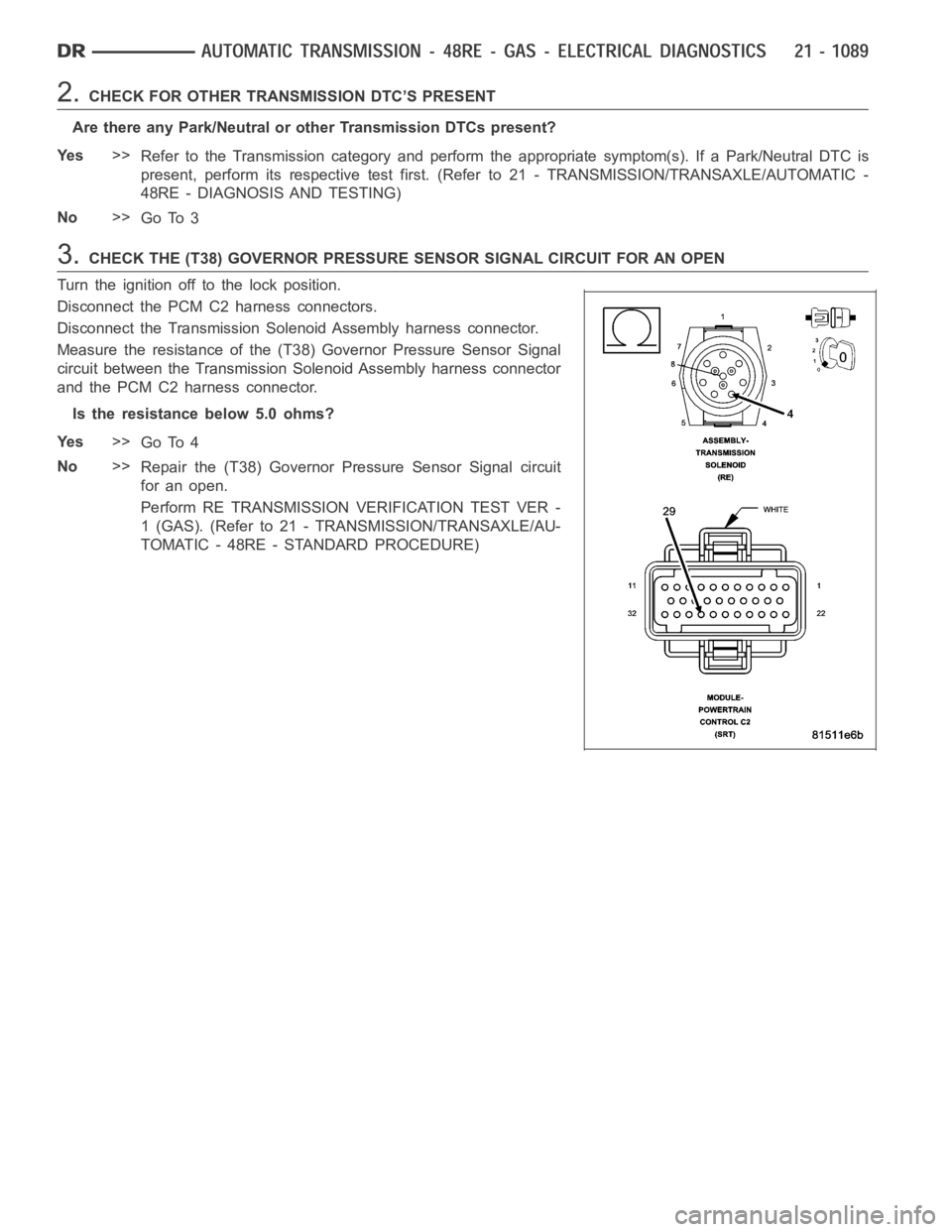
2.CHECK FOR OTHER TRANSMISSION DTC’S PRESENT
Are there any Park/Neutral or other Transmission DTCs present?
Ye s>>
Refer to the Transmission category and perform the appropriate symptom(s). If a Park/Neutral DTC is
present, perform its respective test first. (Refer to 21 - TRANSMISSION/TRANSAXLE/AUTOMATIC -
48RE - DIAGNOSIS AND TESTING)
No>>
Go To 3
3.CHECK THE (T38) GOVERNOR PRESSURE SENSOR SIGNAL CIRCUIT FOR AN OPEN
Turn the ignition off to the lock position.
Disconnect the PCM C2 harness connectors.
Disconnect the Transmission Solenoid Assembly harness connector.
Measure the resistance of the (T38) Governor Pressure Sensor Signal
circuit between the Transmission Solenoid Assembly harness connector
and the PCM C2 harness connector.
Is the resistance below 5.0 ohms?
Ye s>>
Go To 4
No>>
Repair the (T38) Governor Pressure Sensor Signal circuit
for an open.
Perform RE TRANSMISSION VERIFICATION TEST VER -
1 (GAS). (Refer to 21 - TRANSMISSION/TRANSAXLE/AU-
TOMATIC - 48RE - STANDARD PROCEDURE)
Page 3611 of 5267
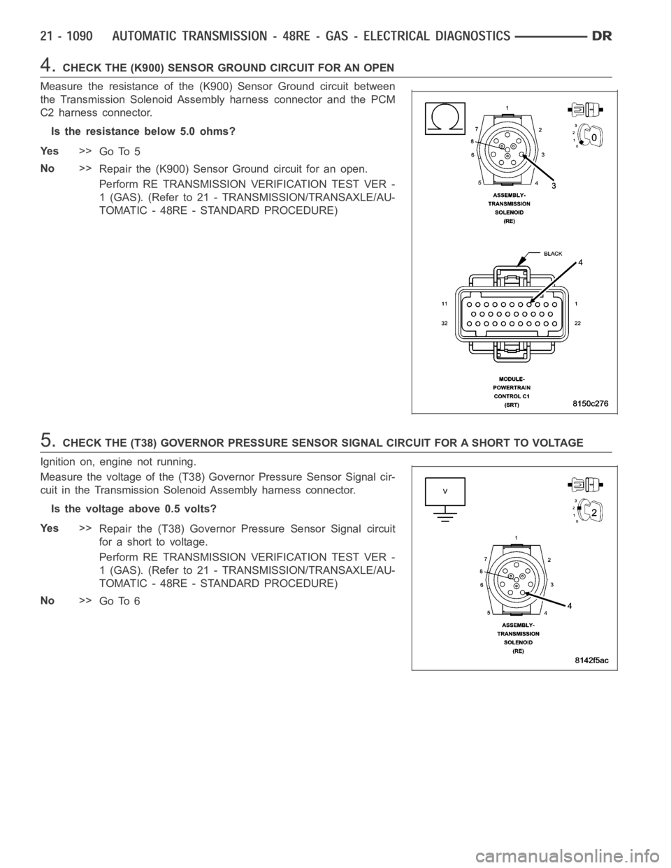
4.CHECK THE (K900) SENSOR GROUND CIRCUIT FOR AN OPEN
Measure the resistance of the (K900) Sensor Ground circuit between
the Transmission Solenoid Assembly harness connector and the PCM
C2 harness connector.
Is the resistance below 5.0 ohms?
Ye s>>
Go To 5
No>>
Repair the (K900) Sensor Ground circuit for an open.
Perform RE TRANSMISSION VERIFICATION TEST VER -
1 (GAS). (Refer to 21 - TRANSMISSION/TRANSAXLE/AU-
TOMATIC - 48RE - STANDARD PROCEDURE)
5.CHECK THE (T38) GOVERNOR PRESSURE SENSOR SIGNAL CIRCUIT FOR A SHORT TO VOLTAGE
Ignition on, engine not running.
Measure the voltage of the (T38) Governor Pressure Sensor Signal cir-
cuit in the Transmission Solenoid Assembly harness connector.
Is the voltage above 0.5 volts?
Ye s>>
Repair the (T38) Governor Pressure Sensor Signal circuit
for a short to voltage.
Perform RE TRANSMISSION VERIFICATION TEST VER -
1 (GAS). (Refer to 21 - TRANSMISSION/TRANSAXLE/AU-
TOMATIC - 48RE - STANDARD PROCEDURE)
No>>
Go To 6
Page 3612 of 5267
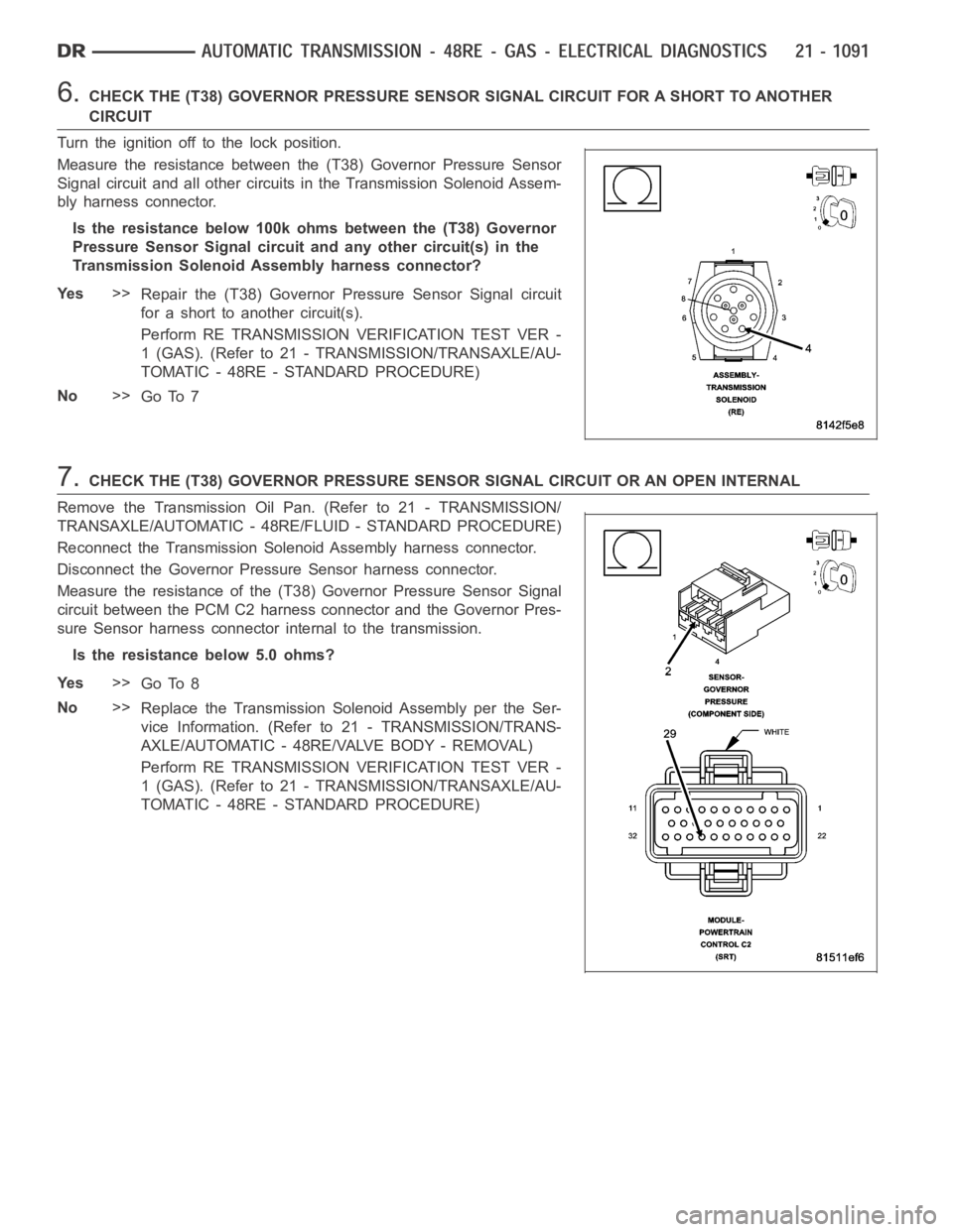
6.CHECK THE (T38) GOVERNOR PRESSURE SENSOR SIGNAL CIRCUIT FOR A SHORT TO ANOTHER
CIRCUIT
Turn the ignition off to the lock position.
Measure the resistance between the (T38) Governor Pressure Sensor
Signal circuit and all other circuits in the Transmission Solenoid Assem-
bly harness connector.
Is the resistance below 100k ohms between the (T38) Governor
Pressure Sensor Signal circuit and any other circuit(s) in the
Transmission Solenoid Assembly harness connector?
Ye s>>
Repair the (T38) Governor Pressure Sensor Signal circuit
for a short to another circuit(s).
Perform RE TRANSMISSION VERIFICATION TEST VER -
1 (GAS). (Refer to 21 - TRANSMISSION/TRANSAXLE/AU-
TOMATIC - 48RE - STANDARD PROCEDURE)
No>>
Go To 7
7.CHECK THE (T38) GOVERNOR PRESSURE SENSOR SIGNAL CIRCUIT OR AN OPEN INTERNAL
Remove the Transmission Oil Pan. (Refer to 21 - TRANSMISSION/
TRANSAXLE/AUTOMATIC - 48RE/FLUID - STANDARD PROCEDURE)
Reconnect the Transmission Solenoid Assembly harness connector.
Disconnect the Governor Pressure Sensor harness connector.
Measure the resistance of the (T38) Governor Pressure Sensor Signal
circuit between the PCM C2 harness connector and the Governor Pres-
sure Sensor harness connector internal to the transmission.
Is the resistance below 5.0 ohms?
Ye s>>
Go To 8
No>>
Replace the Transmission Solenoid Assembly per the Ser-
vice Information. (Refer to 21 - TRANSMISSION/TRANS-
AXLE/AUTOMATIC - 48RE/VALVE BODY - REMOVAL)
Perform RE TRANSMISSION VERIFICATION TEST VER -
1 (GAS). (Refer to 21 - TRANSMISSION/TRANSAXLE/AU-
TOMATIC - 48RE - STANDARD PROCEDURE)
Page 3613 of 5267
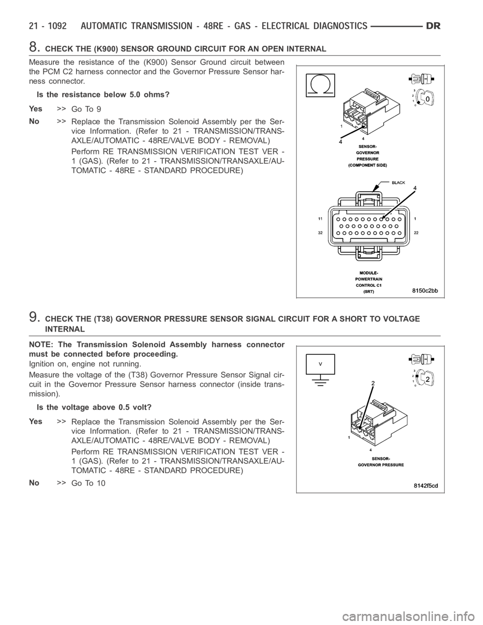
8.CHECK THE (K900) SENSOR GROUND CIRCUIT FOR AN OPEN INTERNAL
Measure the resistance of the (K900) Sensor Ground circuit between
the PCM C2 harness connector and the Governor Pressure Sensor har-
ness connector.
Is the resistance below 5.0 ohms?
Ye s>>
Go To 9
No>>
Replace the Transmission Solenoid Assembly per the Ser-
vice Information. (Refer to 21 - TRANSMISSION/TRANS-
AXLE/AUTOMATIC - 48RE/VALVE BODY - REMOVAL)
Perform RE TRANSMISSION VERIFICATION TEST VER -
1 (GAS). (Refer to 21 - TRANSMISSION/TRANSAXLE/AU-
TOMATIC - 48RE - STANDARD PROCEDURE)
9.CHECK THE (T38) GOVERNOR PRESSURE SENSOR SIGNAL CIRCUIT FOR A SHORT TO VOLTAGE
INTERNAL
NOTE: The Transmission Solenoid Assembly harness connector
must be connected before proceeding.
Ignition on, engine not running.
Measure the voltage of the (T38) Governor Pressure Sensor Signal cir-
cuit in the Governor Pressure Sensor harness connector (inside trans-
mission).
Is the voltage above 0.5 volt?
Ye s>>
Replace the Transmission Solenoid Assembly per the Ser-
vice Information. (Refer to 21 - TRANSMISSION/TRANS-
AXLE/AUTOMATIC - 48RE/VALVE BODY - REMOVAL)
Perform RE TRANSMISSION VERIFICATION TEST VER -
1 (GAS). (Refer to 21 - TRANSMISSION/TRANSAXLE/AU-
TOMATIC - 48RE - STANDARD PROCEDURE)
No>>
Go To 10