Page 3618 of 5267

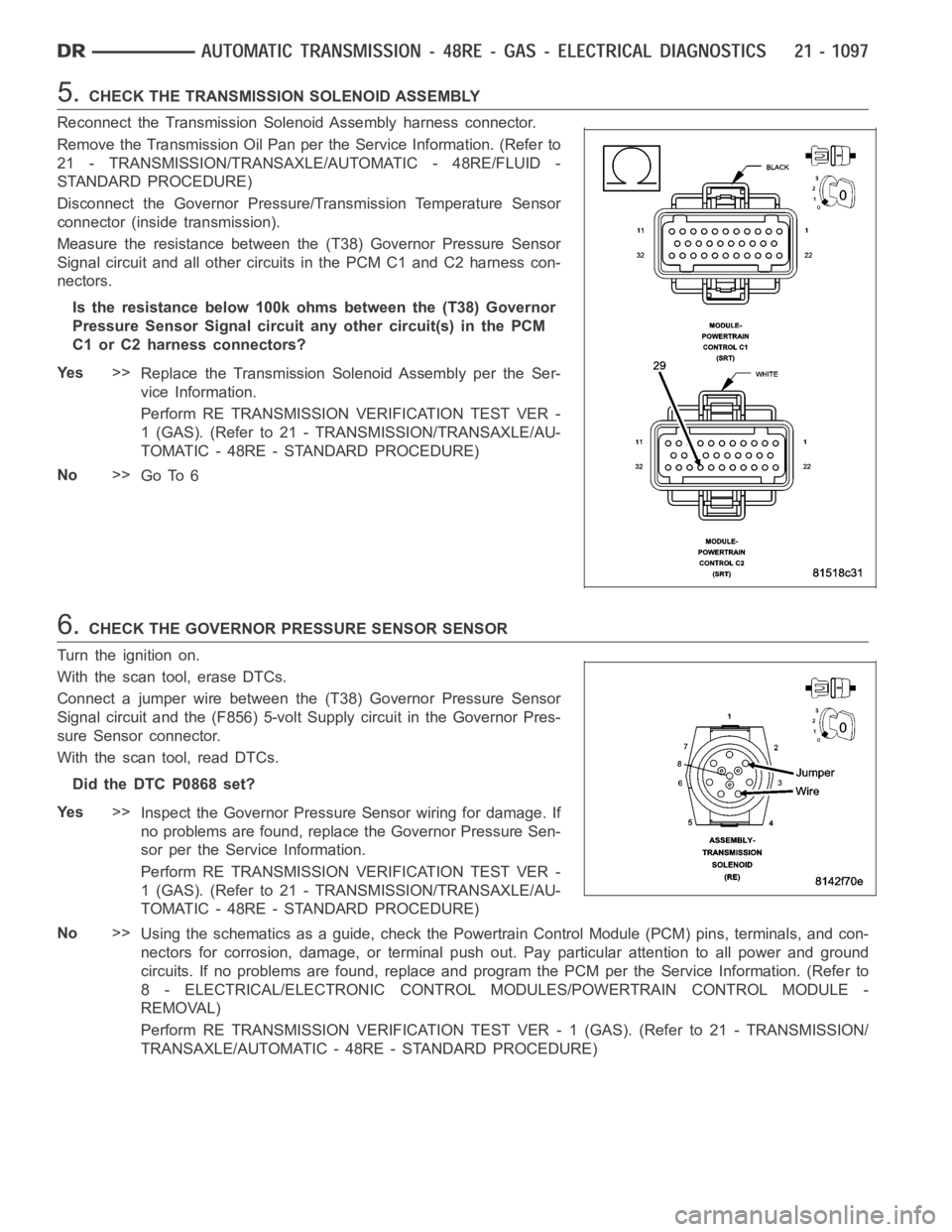
5.CHECK THE TRANSMISSION SOLENOID ASSEMBLY
Reconnect the Transmission Solenoid Assembly harness connector.
Remove the Transmission Oil Pan perthe Service Information. (Refer to
21 - TRANSMISSION/TRANSAXLE/AUTOMATIC - 48RE/FLUID -
STANDARD PROCEDURE)
Disconnect the Governor Pressure/Transmission Temperature Sensor
connector (inside transmission).
Measure the resistance between the (T38) Governor Pressure Sensor
Signal circuit and all other circuits in the PCM C1 and C2 harness con-
nectors.
Is the resistance below 100k ohms between the (T38) Governor
Pressure Sensor Signal circuit any other circuit(s) in the PCM
C1 or C2 harness connectors?
Ye s>>
Replace the Transmission Solenoid Assembly per the Ser-
vice Information.
Perform RE TRANSMISSION VERIFICATION TEST VER -
1 (GAS). (Refer to 21 - TRANSMISSION/TRANSAXLE/AU-
TOMATIC - 48RE - STANDARD PROCEDURE)
No>>
Go To 6
6.CHECK THE GOVERNOR PRESSURE SENSOR SENSOR
Turn the ignition on.
With the scan tool, erase DTCs.
Connect a jumper wire between the (T38) Governor Pressure Sensor
Signal circuit and the (F856) 5-volt Supply circuit in the Governor Pres-
sure Sensor connector.
With the scan tool, read DTCs.
Did the DTC P0868 set?
Ye s>>
Inspect the Governor Pressure Sensor wiring for damage. If
no problems are found, replace the Governor Pressure Sen-
sor per the Service Information.
Perform RE TRANSMISSION VERIFICATION TEST VER -
1 (GAS). (Refer to 21 - TRANSMISSION/TRANSAXLE/AU-
TOMATIC - 48RE - STANDARD PROCEDURE)
No>>
Using the schematics as a guide, check the Powertrain Control Module (PCM)pins, terminals, and con-
nectors for corrosion, damage, or terminal push out. Pay particular attention to all power and ground
circuits. If no problems are found, replace and program the PCM per the Service Information. (Refer to
8 - ELECTRICAL/ELECTRONIC CONTROL MODULES/POWERTRAIN CONTROL MODULE -
REMOVAL)
Perform RE TRANSMISSION VERIFICATION TEST VER - 1 (GAS). (Refer to 21 - TRANSMISSION/
TRANSAXLE/AUTOMATIC - 48RE - STANDARD PROCEDURE)
Page 3619 of 5267
7.INTERMITTENT WIRING AND CONNECTORS
The conditions necessary to set this DTC are not present at this time.
Use the Freeze Frame Data to help duplicate the conditions in which the DTC originally set. Pay particular attention
to the DTC set conditions, such as, VSS, MAP, ECT, and Load
Using the schematics as a guide, visually inspect the related wiring harness. Look for any chafed, pierced, pinched,
or partially broken wires.
Visually inspect the related wiring harness connectors. Look for broken,bent, pushed out, or corroded terminals.
Wiggle the wiring and connectors while checking for any possible open or shorted circuits.
Check for any Service Information Tune-ups or Technical Service Bulletins that may apply.
Were there any problems found?
Ye s>>
Repair as necessary.
Perform RE TRANSMISSION VERIFICATION TEST VER - 1 (GAS). (Refer to 21 - TRANSMISSION/
TRANSAXLE/AUTOMATIC - 48RE - STANDARD PROCEDURE)
No>>
Te s t C o m p l e t e .
Page 3620 of 5267
P1765-TRANS 12 VOLT SUPPLYRELAY CTRL CIRCUIT (GAS)
For a complete wiring diagramRefer to Section 8W
Page 3623 of 5267

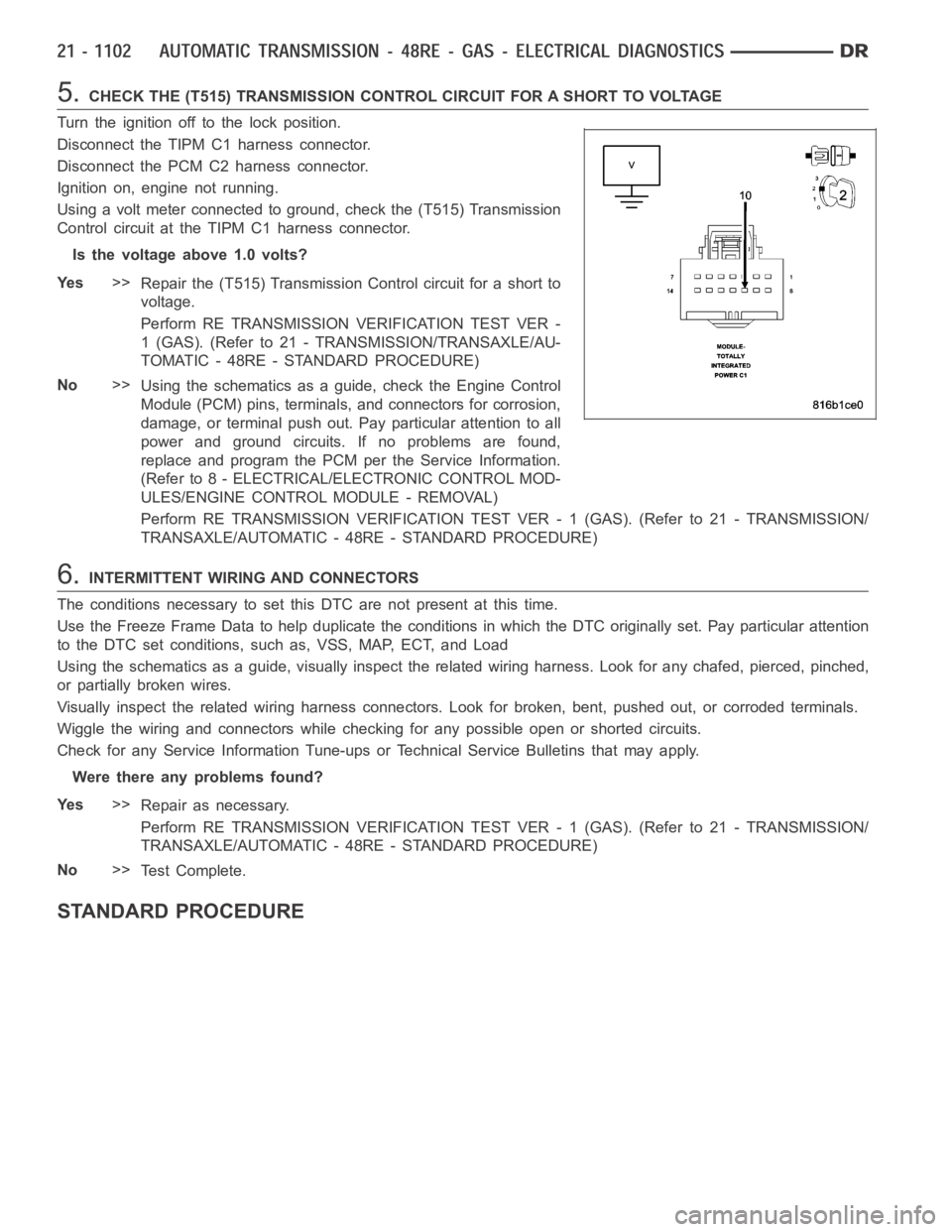
5.CHECK THE (T515) TRANSMISSION CONTROL CIRCUIT FOR A SHORT TO VOLTAGE
Turn the ignition off to the lock position.
Disconnect the TIPM C1 harness connector.
Disconnect the PCM C2 harness connector.
Ignition on, engine not running.
Using a volt meter connected to ground, check the (T515) Transmission
Control circuit at the TIPM C1 harness connector.
Is the voltage above 1.0 volts?
Ye s>>
Repair the (T515) Transmission Control circuit for a short to
voltage.
Perform RE TRANSMISSION VERIFICATION TEST VER -
1 (GAS). (Refer to 21 - TRANSMISSION/TRANSAXLE/AU-
TOMATIC - 48RE - STANDARD PROCEDURE)
No>>
Using the schematics as a guide, check the Engine Control
Module (PCM) pins, terminals, and connectors for corrosion,
damage, or terminal push out. Pay particular attention to all
power and ground circuits. If no problems are found,
replace and program the PCM per the Service Information.
(Refer to 8 - ELECTRICAL/ELECTRONIC CONTROL MOD-
ULES/ENGINE CONTROL MODULE - REMOVAL)
Perform RE TRANSMISSION VERIFICATION TEST VER - 1 (GAS). (Refer to 21 - TRANSMISSION/
TRANSAXLE/AUTOMATIC - 48RE - STANDARD PROCEDURE)
6.INTERMITTENT WIRING AND CONNECTORS
The conditions necessary to set this DTC are not present at this time.
Use the Freeze Frame Data to help duplicate the conditions in which the DTC originally set. Pay particular attention
to the DTC set conditions, such as, VSS, MAP, ECT, and Load
Using the schematics as a guide, visually inspect the related wiring harness. Look for any chafed, pierced, pinched,
or partially broken wires.
Visually inspect the related wiring harness connectors. Look for broken,bent, pushed out, or corroded terminals.
Wiggle the wiring and connectors while checking for any possible open or shorted circuits.
Check for any Service Information Tune-ups or Technical Service Bulletins that may apply.
Were there any problems found?
Ye s>>
Repair as necessary.
Perform RE TRANSMISSION VERIFICATION TEST VER - 1 (GAS). (Refer to 21 - TRANSMISSION/
TRANSAXLE/AUTOMATIC - 48RE - STANDARD PROCEDURE)
No>>
Te s t C o m p l e t e .
STANDARD PROCEDURE
Page 3624 of 5267

PRE-DIAGNOSTIC TROUBLE SHOOTING PROCEDURE - 48RE GAS
For a complete wiring diagramRefer to Section 8W
1.
NOTE: Always perform diagnostics with a fully charged battery to avoid false symptoms.
NOTE: Low fluid level can be the cause of many transmission problems. If thefluid level is low locate and
repair the leak then check and adjust the fluid level per the Service Information.
With the scan tool, read engine DTC’s. Check and repair all engine DTCs prior to performing transmission symptom
diagnostics.
Using the wiring diagram/schematic as a guide, inspect the wiring and connectors. Repair as necessary.
Verify the flash level of the Powertrain Control Module. Some problems arecorrected by software upgrades.
Check for any Service Information Tune-ups or Technical Service Bulletins that may apply.
Did any of the above checks or procedures correct the symptom?
Ye s>>
Repair is complete.
Perform RE TRANSMISSION VERIFICATION TEST VER - 1 (GAS). (Refer to 21 - TRANSMISSION/
TRANSAXLE/AUTOMATIC - 48RE - STANDARD PROCEDURE)
No>>
Refer to the Transmission category and perform the appropriate symptom(s). (Refer to 21 - TRANS-
MISSION/TRANSAXLE/AUTOMATIC - 48RE - DIAGNOSIS AND TESTING)
Page 3628 of 5267
P0711-TRANS TEMP SENSOR, NO TEMP RISE AFTER START (DIESEL)
For a complete wiring diagramRefer to Section 8W.
Page 3631 of 5267

Turn the ignition off to the lock position.
Remove the Transmission Oil Pan per the Service Information. (Refer to 21 -TRANSMISSION/TRANSAXLE/AU-
TOMATIC - 48RE/FLUID - STANDARD PROCEDURE)
Disconnect the Governor Pressure Sensor harness connector internal to the transmission.
NOTE: Check connectors - Clean/repair as necessary
Measure the resistance of the Transmission Temperature Sensor between the (T54) Transmission Temperature Sen-
sor Signal circuit and the (K900) Sensor Ground circuit.
Using the chart at the chart above, compare the Temperature Sensor temperature to the correlating resistance
value.
Is the resistance within the specified range when the sensor is at the giventemperature?
Ye s>>
Te s t C o m p l e t e .
No>>
Replace the Governor Pressure/Transmission Temperature Sensor per the Service Information. (Refer to
21 - TRANSMISSION/TRANSAXLE/AUTOMATIC - 48RE/GOVERNOR PRESSURE SENSOR-
REMOVAL)
Perform RE TRANSMISSION VERIFICATION TEST VER - 1 (DIESEL). (Refer to 21 - TRANSMISSION/
TRANSAXLE/AUTOMATIC - 48RE - STANDARD PROCEDURE)
6.INTERMITTENT WIRING AND CONNECTORS
The conditions necessary to set this DTC are not present at this time.
Use the Freeze Frame Data to help duplicate the conditions in which the DTC originally set. Pay particular attention
to the DTC set conditions, such as, VSS, MAP, ECT, and Load.
Using the schematics as a guide, visually inspect the related wiring harness. Look for any chafed, pierced, pinched,
or partially broken wires.
Visually inspect the related wiring harness connectors. Look for broken,bent, pushed out, or corroded terminals.
Wiggle the wiring and connectors while checking for any possible open or shorted circuits.
Check for any Service Information Tune-ups or Technical Service Bulletins that may apply.
Were there any problems found?
Ye s>>
Repair as necessary.
Perform RE TRANSMISSION VERIFICATION TEST VER - 1 (DIESEL). (Refer to 21 - TRANSMISSION/
TRANSAXLE/AUTOMATIC - 48RE - STANDARD PROCEDURE)
No>>
Te s t C o m p l e t e .
Page 3632 of 5267
P0712-TRANS TEMP SENSOR VOLTAGE TOO LOW (DIESEL)
For a complete wiring diagramRefer to Section 8W