Page 262 of 2893
�
�� Special Tools Required
Tighten: 3/4 Turn Clockwise
Tightening Torque: 12 N·m (1.2 kgf·m, 8.7 lbf·ft)
8-118-11
Engine Oil Filter Replacem")
���
���
�(�#�'�������������������������������
� �����)�
�� Special Tools Required
Tighten: 3/4 Turn Clockwise
Tightening Torque: 12 N·m (1.2 kgf·m, 8.7 lbf·ft)
8-118-11
Engine Oil Filter Replacement
A
B
07HAA-PJ70101
5. Run the engine for more than 3 minutes, then checkfor oil leakage.
6. Turn the ignition switch to LOCK (0).
7. Connect the Honda Diagnostic System (HDS) to the data link connector (DLC) (see step 2 on page 11-3).
8. Turn the ignition switch to ON (II).
9. Make sure the HDS communicates with the vehicle and the engine control module (ECM)/powertrain
control module (PCM). If it does not communicate,
troubleshoot the DLC circuit (see page 11- 204).
10. Select GAUGES in the BODY ELECTRICAL menu with the HDS.
11. Select ADJUSTMENT in the GAUGES menu with the HDS.
12. Select SERVICE REMINDER in the ADJUSTMENT menu with the HDS.
13. Select RESET in the SERVICE REMINDER menu with the HDS.
14. Select RESETTING THE ENGINE OIL LIFE with the HDS.
NOTE: If you changed the automatic transmission
fluid (ATF) at the same time with the engine oil,
select RESETTING THE ENGINE OIL LIFE AND ATF
with the HDS instead. Oil filter wrench 07HAA-PJ70101
1. Remove the oil filter with the oil filter wrench.
2. Inspect the filter to make sure the rubber seal is not stuck to the oil filter seating surface of the engine.
3. Inspect the threads (A) and rubber seal (B) on the new filter. Clean the seat on the engine block, then
apply a light coat of new engine oil to the filter
rubber seal. Use only filters with a built-in bypass
system.
4. Install the oil filter by hand.
5. After the rubber seal seats, tighten the oil filter clockwise with the oil filter wrench.
(cont’d)
08/08/21 14:36:43 61SNR030_080_0011
ProCarManuals.com
DYNOMITE -2009-
Page 265 of 2893
���
�(�#�'�������������������������������
�"�����)���
K20Z3 engine
Torque: 16 N·m (1.6 kgf·m, 12 lbf·ft)
8-14Engine Lubrication
Oil Jet Inspection
1.2 mm (0.05 in.)
1.2 mm
(0.05 in.)
A
B
1. Remove the oil jet, and inspect it as follows. Make sure that a 1.1 mm (0.04 in.) diameter drillwill go through the nozzle hole (A) (1.2 mm
(0.05 in.) diameter).
Insert the other end of a 1.1 mm (0.04 in.) drill into the oil intake (1.2 mm (0.05 in.) diameter).
Make sure the check ball (B) moves smoothly and
has a stroke of approximately 4.0 mm (0.16 in.).
Check the oil jet operation with an air nozzle. It should take at least 200 kPa (2.0 kgf/cm , 28 psi)
to unseat the check ball.
NOTE: Replace the oil jet assembly if the nozzle is
damaged or bent.
2. Carefully install the oil jet. The mounting torque is critical.
2
08/08/21 14:36:45 61SNR030_080_0014
ProCarManuals.com
DYNOMITE -2009-
Page 360 of 2893
 mechanism on the intake camshaft in")
����
i-VTEC
11-37
LOW SPEED CAMHIGH SPEED CAM
HIGH
ENGINE SPEED HIGH
LOW
LOW
ENGINE
LOAD
TORQUE CURVE
The i-VTEC system has a variable valve timing control (VTC) mechanism on the intake camshaft in addition to the
usual VTEC.
This system improves fuel efficiency and reduces exhaust emissions at all levels of engine speed, vehicle speed,
and engine load.
The VTEC system changes the valve lift and timing by using more than one cam profile.
The VTC system changes the phase of the intake camshaft via oil pressure. It changes the intake valve timing continuously.
Driving Condition VTC Control Description
Light-load Base Position For stable combustion, the cam angle is retarded, and reduces the entry of exhaust gas into the cylinder.
Medium/high-load Advance Control Cam phase angle is controlled to optimize valve timing, improving fuel efficiency and reducing
emissions.
High speed Advance-Base Position To reduce pumping loss, the intake valve is closed quickly. This gives the air/fuel mixture a charging
effect that helps to maximize engine power.
(cont’d)
08/08/21 14:13:39 61SNR030_110_0037
ProCarManuals.com
DYNOMITE -2009-
Page 361 of 2893

MAXIMUM VTC ADVANCE 25 °
TDC
EX IN 1IN 2
EX IN 2IN 1
MAXIMUM VTC ADVANCE")
����
�
�
�
�
VTC System
VTEC System
K20Z2 engine
K20Z3 engine
11-38
Fuel and Emissions Systems
System Description (cont’d)
MAXIMUM VTC ADVANCE 25 °
TDC
EX IN 1IN 2
EX IN 2IN 1
MAXIMUM VTC ADVANCE 25 °
SHORT OVERLAP
LONG OVERLAP
LOW SPEED VALVE TIMING HIGH SPEED VALVE TIMING
EX IN EXIN
IN (LOW LIFT)
LOW SPEED VALVE TIMING HIGH SPEED VALVE TIMING
EX IN EX IN
The VTC system makes continuous intake valve timing changes based on operating conditions.
Intake valve timing is optimized to allow the engine to produce maximum power.
Cam angle is advanced to obtain the EGR effect and reduce pumping loss. The intake valve is closed quickly to
reduce the entry of the air/fuel mixture into the intake port and improve the charging effect.
The system reduces the cam advance at idle, stabilizes combustion, and reduces engine speed.
If a malfunction occurs, the VTC system control is disabled and the valve timing is fixed at the fully retarded position.
The VTEC system changes the cam profile to correspond to the engine speed. It maximizes torque at low engine speed and output at high engine speed.
The low lift cam is used at low engine speeds, and the high lift cam is used at high engine speeds.
08/08/21 14:13:40 61SNR030_110_0038
ProCarManuals.com
DYNOMITE -2009-
Page 664 of 2893

A
B
07AAA-SNAA100 A
120 N·m
(12.2 kgf·m, 88.2 lbf·ft) A
A
4. Install a locknut plate (A) and a new loc")
����
��������
����
11-336Fuel Supply System
Fuel Tank Unit Removal and Installation (cont’d)
A
B
07AAA-SNAA100 A
120 N·m
(12.2 kgf·m, 88.2 lbf·ft) A
A
4. Install a locknut plate (A) and a new locknut (B).
5. Using the special tool, tighten the new locknut (A) to the specified torque.
NOTE: After tightening, make sure the marks are still aligned.
After installation, check the base gasket, visually or by hand, to make sure it is not pinched. 6. Connect the fuel tank unit 4P connector, then
connect the quick-connect fitting.
7. Reconnect the negative cable to the battery, and turn the ignition switch to ON (II) (but do not
operate the starter motor). The fuel pump will run
for about 2 seconds, and fuel pressure will rise.
Repeat this two or three times, then check that
there is no leakage in the fuel supply system.
8. Install the access panel (A) to the floor.
9. Install the rear floor upper cross-member (A).
10. Install the rear seat cushion (see page 20-131).
11. Install the fuel fill cap.
08/08/21 14:30:59 61SNR030_110_0336
ProCarManuals.com
DYNOMITE -2009-
Page 755 of 2893

A
07LAB-PV00100
B
K20Z2enginemodel:
12x1.0mm
103 N·m")
������
�� ���
�����
�µ�µ
Crankshaft Pilot Bushing Inspection Crankshaft Pilot Bushing Replacement
12-22Clutch
Clutch Replacement (cont’d)
A
07LAB-PV00100
B
K20Z2enginemodel:
12x1.0mm
103 N·m
(10.5kgf·m,76lbf·ft)
K20Z3enginemodel:
122 N·m
(12.5kgf·m,90lbf·ft) B
07936-KC10500C
07741-0010201
A
C
07746-0010800
B
07749-0010000
2.4 2.6 mm (0.09 0.10 in.)
A
18. Install the flywheel on the crankshaft, and install
the mounting bolts finger-tight.
19. Install the ring gear holder (A), then torque the flywheel mounting bolts (B) in a cri sscross pattern
in several steps.
20. Inspect the crankshaft pilot bushing for wear and damage.
21. Inspect the inside surface of the crankshaft pilot bushing with your finger. If the crankshaft pilot
bushing is not smooth, replace it; then go to step
22. 22. Remove the crankshaft pilot bushing (A) using the
bearing remover shaft (B) and the slide hammer (C).
23. Install a new crankshaft pilot bushing (A) into the crankshaft using the 15 x 135L driver handle (B)
and the 22 x 24 mm bearing driver attachment (C).
08/08/21 14:42:53 61SNR030_120_0024
ProCarManuals.com
DYNOMITE -2009-
Page 756 of 2893

12-23
D
07ZAF-PR8A100
E
07936-3710100
(P/N 08798-9002) C
B (P/N 08798-9002)A
B A D
07936")
����
�
�������
Clutch Disc and Pressure Plate Installation
Specified Torque: 25 N·m (2.6 kgf·m, 19 lbf·ft)
12-23
D
07ZAF-PR8A100
E
07936-3710100
(P/N 08798-9002) C
B (P/N 08798-9002)A
B A D
07936-3710100
C
07ZAF-PR8A100 B
07LAB-PV00100
A
24. Temporarily install the clutch disc onto the splines of the transmission mainshaft. Make sure the clutch
disc slides freely on the mainshaft.
25. Apply a light coat of super high temp urea grease (P/N 08798-9002) to the crankshaft pilot bushing (A).
26. Apply super high temp urea grease (P/N 08798-9002) to the splines (B) of the clutch disc (C),
then install the clutch disc using the clutch
alignment shaft (D) and the remover handle (E).
27. Install the pressure plate (A) and the mounting bolts (B) finger-tight. 28. Torque the mounting bolts (A) in a cri
sscross
pattern. Tighten the bolts in several steps to
prevent warping the diaphragm spring.
29. Remove the ring gear holder (B), the clutch alignment shaft (C), and the remover handle (D).
30. Make sure the diaphragm spring fingers are all the same height.
31. Do the release bearing inspection, and replace it if necessary.
32. Install the transmission; 5-speed model (see page 13-14), 6-speed model (see page 13-91).
(cont’d)
08/08/21 14:42:54 61SNR030_120_0025
ProCarManuals.com
DYNOMITE -2009-
Page 783 of 2893
�
��
����
���������
����
13-12Manual Transmission
Transmission Removal (cont’d)
A
A
BB
A B
C VSB02C000016
A
AB
A
A
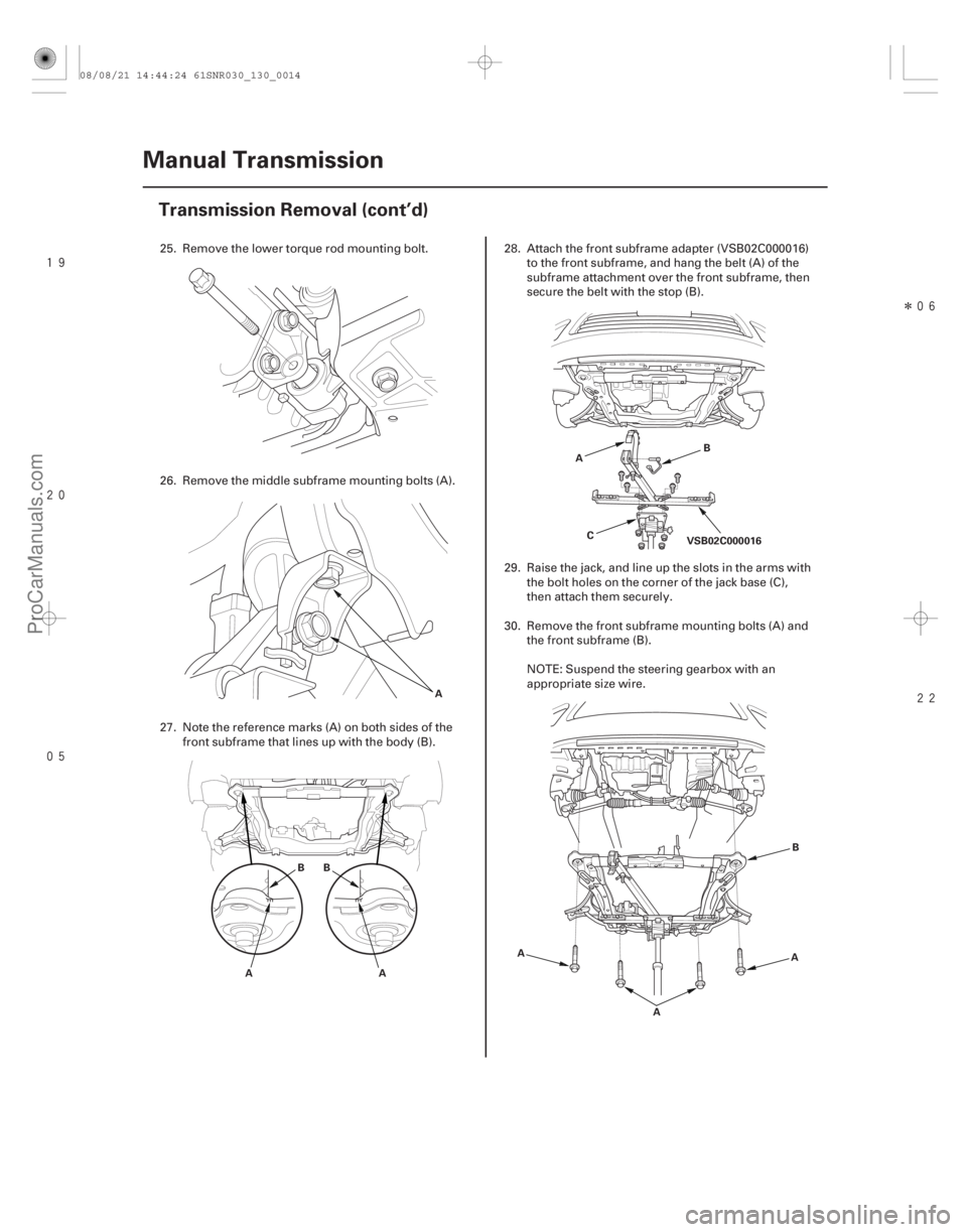
25. Remove the lower torque rod mounting bolt.
26. Remove the middle subframe mounting bolts (A).
27. Note the reference marks (A) on both sides of the
front subframe that lines up with the body (B). 28. Attach the front subframe adapter (VSB02C000016)
to the front subframe, and hang the belt (A) of the
subframe attachment over the front subframe, then
secure the belt with the stop (B).
29. Raise the jack, and line up the slots in the arms with the bolt holes on the corner of the jack base (C),
then attach them securely.
30. Remove the front subframe mounting bolts (A) and the front subframe (B).
NOTE: Suspend the steering gearbox with an
appropriate size wire.
08/08/21 14:44:24 61SNR030_130_0014
ProCarManuals.com
DYNOMITE -2009-