Page 785 of 2893
����
Special Tools Required
13-14
Manual Transmission
Transmission Installation
A
A
A 12x1.25mm
64N·m(6.5kgf·m,47lb")
�Ì
�Ï
���
����
�����
�����
�(�#�'���������������
�����
����������� �����)����
Special Tools Required
13-14
Manual Transmission
Transmission Installation
A
A
A 12x1.25mm
64N·m(6.5kgf·m,47lbf·ft)
12x1.25mm
64N·m(6.5kgf·m,47lbf·ft)
6x1.0mm
12 N·m (1.2 kgf·m, 9 lbf·ft)
Engine hanger adapter VSB02C000015
2006 Civic engine hanger VSB02C000025
Engine support hanger, A and Reds AAR-T 1256
Front subframe adapter VSB02C000016
These special tools are available through the Acura
Canada Technical Tools Department; FAX
866-398-8665/e-mail: ch_technicaltools ch.honda.com
NOTE: Use fender covers to avoid damaging painted
surfaces.
1. Loosen the upper torque rod mounting bolt (A).
2. Made sure that the two dowel pins (A) are installed in the clutch housing.
3. Check the release fork and the release bearing, and reinstall them with the appropriate grease
(see page 12-24).
4. Place the transmission on the transmission jack, and raise it to the engine level. 5. Install the transmission mounting bolts.
6. Install the clutch cover.
7. Install the intermediate shaft (see page 16-27).
8. Install the driveshafts inboard joint (see step 6 on
page 16-21).
08/08/21 14:44:25 61SNR030_130_0016
ProCarManuals.com
DYNOMITE -2009-
Page 786 of 2893
��������
���
13-15
VSB02C000016
B
14x1.5mm
103 N·m
(10.5kgf·m,76lbf·ft)B
14x1.5mm
103 N·m
(10.5kgf·m,76lbf·ft)A
A
BB
A
9. Support the front subframe with the subframe adapter (VSB02C000016) and a jack. 10. Install the front subframe (A). Loosely install new
subframe mounting bolts (B).
11. Align the front subframe reference marks (A) to the body (B), as noted during removal. Tighten the
front subframe mounting bolts to the specified
torque.
(cont’d)
Replace.Replace.
08/08/21 14:44:26 61SNR030_130_0017
ProCarManuals.com
DYNOMITE -2009-
Page 787 of 2893
����
��������
����
13-16Manual Transmission
Transmission Installation (cont’d)
14x1.5mm
88 N·m
(9.0 kgf·m,
65 lbf·ft)
12x1.25mm
74 N·m
(7.5 kgf·m, 55 lbf·ft)
A A
12 x 1.25 mm
64 N·m
(6.5 kgf·m, 47 lbf·ft)
12. Install a new lower torque rod bracket mounting bolt.
13. Install the front engine mount bracket (A) on the transmission and the engine with new bolts. 14. Loosely tighten a new front engine mount
mounting bolt (A), then attach the lower radiator
hose to the front engine mount bracket.
15. Install new middle subframe mounting bolts.
Replace. Replace. Replace.
Replace.
08/08/21 14:44:26 61SNR030_130_0018
ProCarManuals.com
DYNOMITE -2009-
Page 788 of 2893

10x1.25mm
59 N·m (6.0 kgf·m, 43 lbf·ft)
A B
C
10x1.25mm
59 N·m
(6.0 kgf·m, 43 lbf·ft)
10x1.25mm
54 N·m
(5.5 kgf·m,")
�
��
�
�������
�����
13-17
A
B 10x1.25mm
54 N·m
(5.5 kgf·m,
40 lbf·ft)
10x1.25mm
59 N·m (6.0 kgf·m, 43 lbf·ft)
A B
C
10x1.25mm
59 N·m
(6.0 kgf·m, 43 lbf·ft)
10x1.25mm
54 N·m
(5.5 kgf·m,
40 lbf·ft)10 x 1.25 mm
38 N·m
(3.9 kgf·m,
28 lbf·ft) 12x1.25mm
74 N·m
(7.5 kgf·m,
55 lbf·ft)
6x1.0mm
9.8 N·m
(1.0 kgf·m,
7.2 lbf·ft)
12x1.25mm
74 N·m
(7.5 kgf·m,
55 lbf·ft)
12x1.25mm
74 N·m
(7.5 kgf·m, 55 lbf·ft) B
A
A
14x1.5mm
93 N·m
(9.5 kgf·m,
69 lbf·ft)
16. Install the steering gearbox stiffener plate (A) andthe harness clip (B).
17. Install the stiffener plate (A) and the mounting bracket (B). Connect the exhaust mounting rubber
(C).
18. Connect the lower ball joint and the lower arm (see step 8 on page 16-21).
19. Lower the vehicle on the lift. 20. Install the transmission mount bracket (A), and
connect the ground cable (B).
21. Raise the vehicle on the lift.
22. Loosen and retighten the lower torque rod mounting bolt (A).
23. Refill the transmission with the recommended transmission fluid (see page 13-5).
24. Lower the vehicle on the lift.
(cont’d)
Replace.Replace.
Replace.
08/08/21 14:44:27 61SNR030_130_0019
ProCarManuals.com
DYNOMITE -2009-
Page 789 of 2893
�����
���������
�
��
13-18Manual Transmission
Transmission Installation (cont’d)
A
12x1.25mm
64N·m(6.5kgf·m,47lbf·ft)
A
12x1.25m
64 N·m
(6.5 kgf·m,
47 lbf·ft) A
B 10x1.25mm
38 N·m
(3.9 kgf·m,
28 lbf·ft)
25. Tighten the upper torque rod mounting bolt (A).
26. Raise the vehicle on the lift.
27. Tighten the front mount mounting bolt (A). 28. Install the splash shield.
29. Lower the vehicle on the lift.
30. Remove the engine support hanger and the engine
hanger adapter from the engine.
31. Install the engine control module (ECM) bracket (A), then install the clutch pipe clamp (B).
08/08/21 14:44:28 61SNR030_130_0020
ProCarManuals.com
DYNOMITE -2009-
Page 835 of 2893

13-59
Liquid gasket
D
39 N·m
(4.0 kgf·m,
29 lbf·ft)
C
B
A
B
6x1.0mm
12 N·m (1.2 kgf·m, 8.7 lbf·ft)
B
44 N�")
������
�� �����
�����
Specified Torque:
8x1.25mm
27 N·m (2.8 kgf·m, 20 lbf·ft)
13-59
Liquid gasket
D
39 N·m
(4.0 kgf·m,
29 lbf·ft)
C
B
A
B
6x1.0mm
12 N·m (1.2 kgf·m, 8.7 lbf·ft)
B
44 N·m
(4.5 kgf·m, 33 lbf·ft)
G
H
F
A
39 N·m
(4.0 kgf·m,
33 lbf·ft)
6x1.0mm
12 N·m (1.2 kgf·m, 8.7 lbf·ft) D
E
C
C
15. Tighten the 8 mm flange bolts in a crisscross pattern in several steps.
16. Clean any dirt or oil from the mating surface of the change lever assembly and the transmission
housing. Apply liquid gasket, P/N 08718-0001
evenly to the mating surface of the change lever
assembly and the transmission housing. Install the
component within 5 minutes of applying the liquid
gasket.
NOTE: If you apply liquid gasket P/N 08718-0012, the component must be installed within 4 minutes.
If too much time has passed after applying the liquid gasket, remove the old liquid gasket and
residue, then reapply new liquid gasket. 17. Installthe8x14mmdowelpins(B)andthechange
lever assembly (C) with harness bracket A.
18. Apply liquid gasket, P/N 08718-0001, evenly to the threads of the inter lock bolt (D). Install the
component within 5 minutes of applying the liquid
gasket.
NOTE: If you apply liquid gasket P/N 08718-0012, the component must be installed within 4 minutes.
If too much time has passed after applying the liquid gasket, remove the old liquid gasket and
residue, then reapply new liquid gasket.
19. Install the drain plug (A) and the 10 mm flange bolt (B) with new washers (C). Install the filler plug (D)
finger-tight with new sealing washer (E).
20. Apply MTF to a new O-ring (F). Then install the output shaft (countershaft) speed sensor (G) with
the O-ring and the plain washer (H).
(cont’d)
Replace.Replace.
Replace.
Replace.
08/08/21 14:46:29 61SNR030_130_0061
ProCarManuals.com
DYNOMITE -2009-
Page 858 of 2893
�
��
����
���
�����
�����
13-89
A
A BB
A B
C VSB02C000016
A
AB
A
A
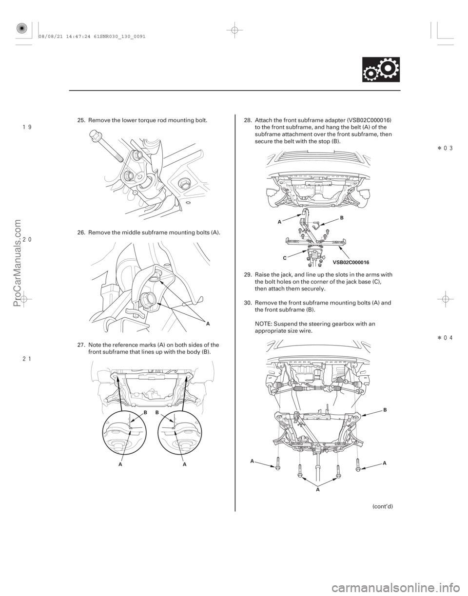
25. Remove the lower torque rod mounting bolt.
26. Remove the middle subframe mounting bolts (A).
27. Note the reference marks (A) on both sides of the
front subframe that lines up with the body (B). 28. Attach the front subframe adapter (VSB02C000016)
to the front subframe, and hang the belt (A) of the
subframe attachment over the front subframe, then
secure the belt with the stop (B).
29. Raise the jack, and line up the slots in the arms with the bolt holes on the corner of the jack base (C),
then attach them securely.
30. Remove the front subframe mounting bolts (A) and the front subframe (B).
NOTE: Suspend the steering gearbox with an
appropriate size wire.
(cont’d)
08/08/21 14:47:24 61SNR030_130_0091
ProCarManuals.com
DYNOMITE -2009-
Page 860 of 2893
����
Special Tools Required
Front side
Rear side
13-91
Transmission Installation
A
A
A 12x1.25mm
64 N·m
(6.5 kgf·m,
47")
�Ì
�Ï
���
����
����
�����
�(�#�'���������������
�����
����������� �����)����
Special Tools Required
Front side
Rear side
13-91
Transmission Installation
A
A
A 12x1.25mm
64 N·m
(6.5 kgf·m,
47 lbf·ft)
12x1.25mm
64 N·m
(6.5 kgf·m, 47 lbf·ft)
Engine hanger adapter VSB02C000015
2006 Civic engine hanger VSB02C000025
Engine support hanger, A and Reds AAR-T 1256
Front subframe adapter VSB02C000016
These special tools are available through the Acura
Canada Technical Tools Department; FAX
866-398-8665/e-mail: ch_technicaltools ch.honda.com
NOTE: Use fender covers to avoid damaging painted
surfaces.
1. Loosen the upper torque rod mounting bolt (A).
2. Make sure the two dowel pins (A) are installed in the clutch housing. 3. Check the release fork and the release bearing, and
reinstall them with appropriate grease (see page
12-24).
4. Place the transmission on the transmission jack, and raise it to engine level.
5. Install the transmission mounting bolts.
(cont’d)
08/08/21 14:47:25 61SNR030_130_0093
ProCarManuals.com
DYNOMITE -2009-