Page 380 of 2893
�����
11-57
ETCS
CONTROL
RELAY
A/C COMPRESSOR
CLUTCH RELAY
ELD BATTERY
UNDER-HOOD FUSE/RELAY BOX
WHT
BRN D1
ORN D4
WHT D8
YEL A1
ORN A3
BLK A2
G301 GRY
PUR E6
BLU E7
ORN
E5
E1
LT BLU
C1
IG1ETCS 21
WHT P
M
A23
ELD U RED
F20
PNK
F16 F14
GRN
F9 F7
ORN
F6
YEL
F5
A14
ACC A21
SUBRLY A5
FANH A6
MRLY A4
FANL A8
IGP A20
ETCSRLY
ORN L
AD
AC AE
ABAA
Z PGM-FI
SUBRELAY
PGM-FI
MAIN
RELAY 1
IGNITION
COIL
RELAYA/C
CONDENSER
FAN RELAY
COOLING
FAN
CONTROL
RELAY
RADIATOR
FAN RELAY
9
10
ORN
ORN YEL/BLK
A
AH
F19
H1
C101 PUR
C101
PUR
G1
15
3
(cont’d)
08/08/21 14:13:52 61SNR030_110_0057
ProCarManuals.com
DYNOMITE -2009-
Page 387 of 2893
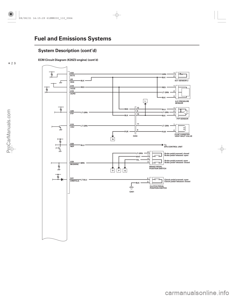
�Î����ECM Circuit Diagram (K20Z3 engine) (cont’d)
11-64Fuel and Emissions Systems
System Description (cont’d)
ECT SENSOR 2
1
A33
ECT2
2
A9
SG6 GRN
BLK
A/C PRESSURE
SENSOR
1
A19
VCC6 RED
2
A16
ACPD LT GRN
3
BLK
1
FTP SENSOR
2
A26
FTP
3
BLK
1
A10
VSV LT GRN
LT GRN
EVAP CANISTER
VENT SHUT VALVE
2
PUR
A28
NEP BLU
To
EPS CONTROL UNIT
3
A39
BKSWNC BRN Brake pedal pressed: closed
Brake pedal released: open
Brake pedal pressed: open
Brake pedal released: closed
4
YEL 1
WHT 2
LT GRN 12
9
10
11 8
RED
BLK
PUR C204
O Q
P BRAKE PEDAL
POSITION SWITCH
N
LT BLU Clutch pedal pressed: open
Clutch pedal released: closed
CLUTCH PEDAL
POSITION SWITCH
A41
CRMTCLS L
BLK 3 2
G401 BLU
LT GRN
LT GRN RED BLK
08/08/21 14:15:29 61SNR030_110_0064
ProCarManuals.com
DYNOMITE -2009-
Page 390 of 2893
�����
11-67
ETCS
CONTROL
RELAY
A/C COMPRESSOR
CLUTCH RELAY
ELD BATTERY
UNDER-HOOD FUSE/RELAY BOX
WHT H1
BRN D1
ORN D4
WHT D8
YEL A1
ORN A3
BLK A2
G301 GRY
PUR E6
BLU E7
ORN
E5 E1
LT BLU
C1
IG1ETCS 21
C101
WHT K
J
A23
ELD Q RED
F20
PUR
F19
F16 F14
GRN
F9
F7
ORN
F6
YEL
F5
A14
ACC A21
SUBRLY A5
FANH A6
MRLY A4
FANL A8
IGP A20
ETCSRLY
ORN I
U
Y Z
XW
V N
PGM-FI
SUBRELAYPGM-FI
MAIN
RELAY 1
IGNITION
COIL
RELAYA/C
CONDENSER
FAN RELAY
COOLING
FAN
CONTROL
RELAY
RADIATOR
FAN RELAY
G1
9
10
ORN
ORN C101
YEL/BLK
A
PURPNK
15
3
(cont’d)
08/08/21 14:15:31 61SNR030_110_0067
ProCarManuals.com
DYNOMITE -2009-
Page 391 of 2893
 (cont’d)
11-68Fuel and Emissions Systems
System Description (cont’d)
PGM-FI MAIN
RELAY 2
(FUEL PUMP)
UNDER-DASH FUSE/RELAY BOX
STARTER
CUT RELAY
(ST")
�����
�´
ECM Circuit Diagram (K20Z3 engine) (cont’d)
11-68Fuel and Emissions Systems
System Description (cont’d)
PGM-FI MAIN
RELAY 2
(FUEL PUMP)
UNDER-DASH FUSE/RELAY BOX
STARTER
CUT RELAY
(ST CUT)
F5
YEL
F8
PNK
F10
BRN
F11
BRN
F24
F25
LT GRN
F30
LT GRN
F31
WHT
F29
G2
ORN
G4
ORN
G12
BRN
G16
WHT
G20
WHT
Q1
WHT
Q5
ORN
Q8
LT BLU
E9
GRN
E27
YEL
IG2
B IG1
D1
WHT
D2
BLU
C3
ORN
C1
YEL
3 UOPY
V
X
C36 IG1
A44 S-NET5V
A15 IMOFPR
A31
SCS
A40
BKSW
G401 BLK/GRN
C101 2
BLK
TRS
ST6
4
1
M
IGNITION SWITCH MICU
FUEL PUMP P
2
4
BLK
1
2
CLUTCH
INTERLOCK
SWITCH ZW
Clutch pedal pressed: closed
Clutch pedal released: open
IG1 HOT in ON (II)
and START (III)
ORN
G601BRN
22
UNDER-HOOD FUSE/RELAY BOX:
No. 21 DBW (THROTTLE
ACTUATOR CONTROL) (15 A) No. 18 IG COIL (15 A)
No.19FIMAIN(15A)
No.11FISUB(15A)
No.15OILLVL(7.5A)
No. 2 IG MAIN (50 A)
No. 23 BACK UP (10 A)
No.12STOP&HORN(15A)
No. 1 MAIN FUSE (100 A)
UNDER-DASH FUSE/RELAY BOX: No. 3 ALTERNATOR (10 A)
No. 2 FUEL PUMP (15 A)
No. 36 IG2 HAC (A/C) (10 A)
08/08/21 14:15:32 61SNR030_110_0068
ProCarManuals.com
DYNOMITE -2009-
Page 622 of 2893
����
������(�#�'���������������������
�����������������)����
11-297
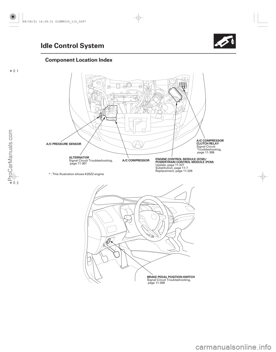
Idle Control System
Component Location Index
ALTERNATOR
A/C PRESSURE SENSOR
A/C COMPRESSOR
CLUTCH RELAY
A/C COMPRESSOR ENGINE CONTROL MODULE (ECM)/
POWERTRAIN CONTROL MODULE (PCM)
BRAKE PEDAL POSITION SWITCH
Signal Circuit Troubleshooting,
page 11-307 Signal Circuit
Troubleshooting,
page 11-306
Update, page 11-227
Substitution, page 11-7
Replacement, page 11-228
* : This illustration shows K20Z2 engine
Signal Circuit Troubleshooting,page 11-308
08/08/21 14:28:31 61SNR030_110_0297
ProCarManuals.com
DYNOMITE -2009-
Page 631 of 2893
���
�µ
�µ�µ �µ
�µ
�µ
�µ
�µ
YES
NO YES
NO
YES
NO
YES
NO
11-30611-306Idle Control System
DTC Troubleshooting (cont’d) A/C Signal Circuit Troubles")
�(�#�'���������������������
�
���
���
�������)���
�µ
�µ�µ �µ
�µ
�µ
�µ
�µ
YES
NO YES
NO
YES
NO
YES
NO
11-30611-306Idle Control System
DTC Troubleshooting (cont’d) A/C Signal Circuit Troubleshooting
37. Check for Temporary DTCs or DTCs with the HDS.
Check for poor connections or loose
terminals at the A/C pressure sensor and the ECM/
PCM. If the ECM/PCM was updated, substitute a
known-good ECM/PCM (see page 11-7), then go to
step 34. If the ECM/PCM was substituted, go to step
1.
If the ECM/PCM was updated, troubleshooting
is complete. If the ECM/PCM was substituted,
replace the original ECM/PCM (see page 11-228). If
any other Temporary DTCs or DTCs are indicated,
go to the indicated DTC’s troubleshooting. 1. Start the engine, and let it idle.
2. Turn the blower switch on.
3. Turn the A/C switch on.
4. Check the A/C CLUTCH in the DATA LIST with the
HDS.
Go to step 5.
Do the A/C system test (see page 21-99).
5. Check the A/C system.
The air conditioning system circuit is OK.
Go to step 6.
6. Turn the ignition switch to LOCK (0).
7. Turn the ignition switch to ON (II).
8. Activate the A/C CLUTCH in the INSPECTION MENU with the HDS.
Do the A/C system test (see page 21-99).
Go to step 9.
9. Turn the ignition switch to LOCK (0).
10. Jump the SCS line with the HDS.
11. Disconnect ECM/PCM connector A (44P).
12. Turn the ignition switch to ON (II).
Is DT C P0533 ind icated ?
Does it indicate ON?
Does t he A/ C sy st em oper at e?
I s t her e a cl i ck i ng noi se f r om t he A/ C compr essorclutch?
08/08/21 14:29:36 61SNR030_110_0306
ProCarManuals.com
DYNOMITE -2009-
Page 632 of 2893
����
�µ
�µ �µ
�µ
�µ
�µ
YES
NO
YES
NO
YES
NO
11-30711-307
Alternator FR Signal Circuit
Troubleshooting
ECM/PCM CONNECTOR A (44P)
ACC (RED)J")
����
���
�(�#�'���������������������
�
�������
�������)����
�µ
�µ �µ
�µ
�µ
�µ
YES
NO
YES
NO
YES
NO
11-30711-307
Alternator FR Signal Circuit
Troubleshooting
ECM/PCM CONNECTOR A (44P)
ACC (RED)JUMPER WIRE
ECM/PCM CONNECTOR B (44P)ALTF
(WHT/RED)
13. Momentarily connect ECM/PCM connector terminalA14 to body ground with a jumper wire s everal
times.
Update the ECM/PCM if it does not have the
latest software (see page 11-227), or substitute a
known-good ECM/PCM (see page 11-7), then
recheck. If the symptom/indication goes away with
a known-good ECM/PCM, replace the original ECM/
PCM (see page 11-228).
Check for poor connections or loose terminals
attheA/CclutchrelayandtheECM/PCM.Ifthe
connections and the terminals are OK, check the
A/C compressor clutch relay (see page 22-70),
repair open in the wires between the ECM/PCM
(A14), the A/C compressor clutch relay, and other
A/C systems parts. 1. Start the engine, and let it idle.
2. Monitor the ALTERNATOR in the DATA LIST with
the HDS.
3. Check if the indicated percentage varies when the headlight switch is turned on.
The alternator signal circuit is OK.
Go to step 4.
4. Turn the headlight switch and ignition switch to LOCK (0).
5. Jump the SCS line with the HDS.
6. Disconnect the alternator 4P connector.
7. Disconnect ECM/PCM connector B (44P).
8. Check for continuity between body ground and ECM/PCM connector terminal B43.
Repair short in the wire between the ECM/
PCM (B43) and the alternator.
Update the ECM/PCM if it does not have the
latest software (see page 11-227), or substitute a
known-good ECM/PCM (see page 11-7), then
recheck. If the symptom/indication goes away with
a known-good ECM/PCM, replace the original ECM/
PCM (see page 11-228).
Terminal side of female terminals
Terminal side of female terminals
I s t her e a cl i ck i ng noi se f r om t he A/ C compr essorclutch? Does t he per cent age v ar y ?
Is there continuity?
08/08/21 14:29:37 61SNR030_110_0307
ProCarManuals.com
DYNOMITE -2009-
Page 633 of 2893
����
�µ
�µ �µ
�µ
�µ
�µ
YES
NO
YES
NO
YES
NO
11-30711-307
Alternator FR Signal Circuit
Troubleshooting
ECM/PCM CONNECTOR A (44P)
ACC (RED)J")
����
���
�(�#�'���������������������
�
�������
�������)����
�µ
�µ �µ
�µ
�µ
�µ
YES
NO
YES
NO
YES
NO
11-30711-307
Alternator FR Signal Circuit
Troubleshooting
ECM/PCM CONNECTOR A (44P)
ACC (RED)JUMPER WIRE
ECM/PCM CONNECTOR B (44P)ALTF
(WHT/RED)
13. Momentarily connect ECM/PCM connector terminalA14 to body ground with a jumper wire s everal
times.
Update the ECM/PCM if it does not have the
latest software (see page 11-227), or substitute a
known-good ECM/PCM (see page 11-7), then
recheck. If the symptom/indication goes away with
a known-good ECM/PCM, replace the original ECM/
PCM (see page 11-228).
Check for poor connections or loose terminals
attheA/CclutchrelayandtheECM/PCM.Ifthe
connections and the terminals are OK, check the
A/C compressor clutch relay (see page 22-70),
repair open in the wires between the ECM/PCM
(A14), the A/C compressor clutch relay, and other
A/C systems parts. 1. Start the engine, and let it idle.
2. Monitor the ALTERNATOR in the DATA LIST with
the HDS.
3. Check if the indicated percentage varies when the headlight switch is turned on.
The alternator signal circuit is OK.
Go to step 4.
4. Turn the headlight switch and ignition switch to LOCK (0).
5. Jump the SCS line with the HDS.
6. Disconnect the alternator 4P connector.
7. Disconnect ECM/PCM connector B (44P).
8. Check for continuity between body ground and ECM/PCM connector terminal B43.
Repair short in the wire between the ECM/
PCM (B43) and the alternator.
Update the ECM/PCM if it does not have the
latest software (see page 11-227), or substitute a
known-good ECM/PCM (see page 11-7), then
recheck. If the symptom/indication goes away with
a known-good ECM/PCM, replace the original ECM/
PCM (see page 11-228).
Terminal side of female terminals
Terminal side of female terminals
I s t her e a cl i ck i ng noi se f r om t he A/ C compr essorclutch? Does t he per cent age v ar y ?
Is there continuity?
08/08/21 14:29:37 61SNR030_110_0307
ProCarManuals.com
DYNOMITE -2009-