Page 767 of 2893
���
�����
12-16 Clutch
Slave Cylinder Replacement (cont’d)
D
A
B
C
(P/N 08798-9002)
(P/N 08C30-B0234M)
A
B (P/N 08798-9002)
C D
E
22 N·m
(2.2 kgf·m, 16 lbf·ft)
3. Install a new O-ring (A) on the clutch line (B), then
connect the clutch line to the slave cylinder (C).
4. Set in new roll pins (D) to the slave cylinder.
5. Pull back the boot (A), and apply s ilicone grease
(P/N 08C30-B0234M) to the boot and the slave
cylinder pushrod (B). Reinstall the boot.
6. Apply a light coat of super high temp urea grease (P/N 08798-9002) to the pushrod of the slave
cylinder (C) and the release fork (D).
7. Install the slave cylinder and the clutch line bracket (E). 8. Do the clutch hydraulic system bleeding (see page
12-7).
9. Check the clutch operation, and check for leaks.
10. Test-drive the vehicle.
Replace.
Replace.
08/08/21 14:42:35 61SNR030_120_0018
ProCarManuals.com
DYNOMITE -2009-
Page 768 of 2893
����
12-17
Clutch Hose Replacement
B
A
A
B C
C A
B
C
B
A
15 N·m
(1.5 kgf·m,
1.1 lbf·ft)
B
NOTE:
Replace the clutch hose if")
���
����
�����
����
�(�#�'���������������
�
�����
�����
��� �����)����
12-17
Clutch Hose Replacement
B
A
A
B C
C A
B
C
B
A
15 N·m
(1.5 kgf·m,
1.1 lbf·ft)
B
NOTE:
Replace the clutch hose if it is twisted, cracked, or if it leaks.
Use fender covers to avoid damaging painted surfaces.
Do not spill brake fluid on the vehicle. It may damage the paint or plastic. If brake fluid does contact the
paint or plastic, wash it off immediately water.
1. Remove the brake fluid from the clutch master cylinder reservoir with a syringe or other suitable
device.
2. Disconnect the clutch hose (A) from the clutch lines (B).
3. Remove the clutch hose clips (A) from the clutch hose (B).
4. Remove the clutch hose from the clutch hose brackets (C). 5. Install the new clutch hose (A) into the clutch hose
brackets (B) with new clutch hose clips (C).
NOTE: Check the clutch hose for interference and
twisting.
6. Connect the clutch lines (A) to the clutch hose (B).
7. Do the clutch hydraulic system bleeding (see page 12-7).
8. Check the clutch operation, and check for leaks.
9. Test-drive the vehicle.
Replace.
08/08/21 14:42:36 61SNR030_120_0019
ProCarManuals.com
DYNOMITE -2009-
Page 769 of 2893
���
��������
�(�#�'���������������
�
�����
��������� �����)����
12-18 Clutch
Clutch Pedal Cover Replacement
A
B
C
A
B
C A
B B
NOTE: This procedure is for models equipped with a
metal clutch pedal plate model.
1. Cover the carpet under the clutch pedal to pr event
metal shavings from getting on the carpet.
2. Center-punch each of the rivets (A), and drill their heads off with a 3 mm (0.12 in.) drill bit (B).
NOTE: Do not drill the clutch pedal pad (C).
3. Remove the clutch pedal plate (A) and the clutch pedal cover (B) from the clutch pedal pad (C). 4. Set the clutch pedal cover to the clutch pedal plate.
5. Install the clutch pedal plate (A) with the rivets (B)
firmly.
6. Using your hand, make sure the clutch pedal cover is firmly fastened to the pedal.
7. Check the clutch pedal height (see page 12-8).
08/08/21 14:42:37 61SNR030_120_0020
ProCarManuals.com
DYNOMITE -2009-
Page 775 of 2893
���
Symptom Diagnostic procedure
13-4
Manual Transmission
Symptom Troubleshooting Index
")
�(�#�'���������������
�����������������������)���
Symptom Diagnostic procedure
13-4
Manual Transmission
Symptom Troubleshooting Index
Hard to shift into 1st gear Check and/or replace the MTF (see page 13-5).
Check the clutch (see page 12-19).
Check the 1st synchro ring and 1st gear (see page 13-50).
Check the 1st/2nd synchro sleeve and hub (see page 13-50).
Check the change lever assembly (see page 13-28).
Hard to shift into 2nd gear Check and/or replace the MTF (see page 13-5). Check the 2nd synchro ring and 2nd gear (see page 13-50).
Check the 1st/2nd synchro sleeve and hub (see page 13-50).
Check the change lever assembly (see page 13-28).
Hard to shift into 3rd gear Check and/or replace the MTF (see page 13-5). Check the 3rd synchro ring and 3rd gear (see page 13-50).
Check the 3rd/4th synchro sleeve and hub (see page 13-50).
Check the change lever assembly (see page 13-28).
Hard to shift into 4th gear Check and/or replace the MTF (see page 13-5). Check the 4th synchro ring and 4th gear (see page 13-50).
Check the 3rd/4th synchro sleeve and hub (see page 13-50).
Check the change lever assembly (see page 13-28).
Hard to shift into 5th gear Check and/or replace the MTF (see page 13-5). Check the 5th synchro ring and 5th gear (see page 13-50).
Check the 5th synchro sleeve and hub (see page 13-50).
Check the change lever assembly (see page 13-28).
Hard to shift into reverse Check and/or replace the MTF (see page 13-5). Check the clutch (see page 12-19).
Check the reverse shift fork and the reverse idler gear (see page 13-27).
Check reverse gear.
Check the change lever assembly (see page 13-28).
Noise from the transmission Check and/or replace the MTF (see page 13-5). Check the transmission gears.
Check the transmission bearings.
Check the differential carrier, the final driven gear, and the carrier bearings.
Shift lever does not operate
smoothly Check and/or replace the MTF (see page 13-5).
Check the shift cable and their joints (see page 13-61).
Check the shift lever
housing with the shift lever shaft.
Transmission jumps out of gear Check and/or replace the MTF (see page 13-5). Check the detent ball springs.
Check the teeth of the synchro rings and gears (see page 13-50).
Check for bent, deform, or damage of the shift forks.
08/08/21 14:44:17 61SNR030_130_0006
ProCarManuals.com
DYNOMITE -2009-
Page 778 of 2893
����
Special Tools Required
13-7
Transmission Removal
A
B C
D
A A
B
A
B C
Engine hanger adapter
VSB02C000015
2006 Civic engine")
�Ì
�Ï
���
����
����
�(�#�'���������������
�����
����������� �����)����
Special Tools Required
13-7
Transmission Removal
A
B C
D
A A
B
A
B C
Engine hanger adapter
VSB02C000015
2006 Civic engine hanger VSB02C000025
Engine support hanger, A and Reds AAR-T 1256
Front subframe adapter VSB02C000016
These special tools are available through the Acura
Canada Technical Tools Department; FAX
866-398-8665/e-mail: ch_technicaltools ch.honda.com
NOTE: Use fender covers to avoid damaging painted
surfaces.
1. Do the battery removal procedure (see page 22-69).
2. Remove the cowl cover and the under-cowl panel (see page 20-163).
3. Remove the air cleaner assembly (see page 11-345).
4. Remove the harness clips (A) and the intake air duct (B), then remove the battery base (C) with the
coolant reservoir (D). 5. Remove the clutch line bracket (A), then carefully
move the slave cylinder (B) out of the way to avoid
bending the clutch line.
NOTE: Do not press the clutch pedal after the slave
cylinder has been moved.
6. Disconnect the back-up light switch connector (A), the output shaft (countershaft) speed sensor
connector (B), and the harness clips (C).
(cont’d)
08/08/21 14:44:19 61SNR030_130_0009
ProCarManuals.com
DYNOMITE -2009-
Page 779 of 2893
����
���������
����
’06 model
’07-09 models
13-8 Manual Transmission
Transmission Removal (cont’d)
C
A
A
DD
C
B
D D A
B
C
A
A
7. Remove the cotter pins (A) or the lock pins (B) and the shift cable bracket (C), then disconnect the shift
cables (D) from the change lever assembly.
Carefully remove both cables and the bracket
together to avoid bending the cables. 8. Remove the harness clips (A) from the clutch cable
bracket (B) and the harness bracket (C).
9. Remove the air cleaner housing bracket (A).
08/08/21 14:44:20 61SNR030_130_0010
ProCarManuals.com
DYNOMITE -2009-
Page 781 of 2893
�
�
�
���
��
����
13-10Manual Transmission
Transmission Removal (cont’d)
A
B
B
B
A
B A
B
C
DB
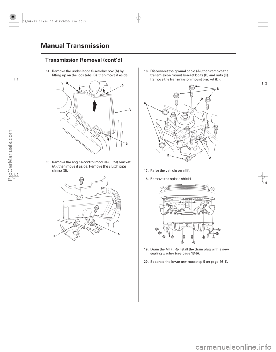
14. Remove the under-hood fuse/relay box (A) by
lifting up on the lock tabs (B), then move it aside.
15. Remove the engine control module (ECM) bracket (A), then move it aside. Remove the clutch pipe
clamp (B). 16. Disconnect the ground cable (A), then remove the
transmission mount bracket bolts (B) and nuts (C).
Remove the transmission mount bracket (D).
17. Raise the vehicle on a lift.
18. Remove the splash shield.
19. Drain the MTF. Reinstall the drain plug with a new sealing washer (see page 13-5).
20. Separate the lower arm (see step 5 on page 16-4).
08/08/21 14:44:22 61SNR030_130_0012
ProCarManuals.com
DYNOMITE -2009-
Page 784 of 2893
�����
�����
13-13
31. Pry out the driveshafts inboard joint (see step 8 onpage 16-5).
32. Remove the intermediate shaft (see page 16-23).
33. Remove the clutch cover.
34. Support the transmission with a transmission jack.
35. Remove the transmission mounting bolts. 36. Pull the transmission away from the engine until
the transmission mainshaft clears the clutch
pressure plate.
37. Slowly lower the transmission about 150 mm (6 in.). Check once again that all hoses and harnesses are
disconnected and free from the transmission, then
lower it completely.
08/08/21 14:44:24 61SNR030_130_0015
ProCarManuals.com
DYNOMITE -2009-