Page 96 of 2893
����Signal to be
tested Test condition Parameter: Desired
resultPossible cause if result is not obtained
4-47
Cruise Control Input Test
NOTE: Always make")
�(�#�'�����������
���������������������������)����Signal to be
tested Test condition Parameter: Desired
resultPossible cause if result is not obtained
4-47
Cruise Control Input Test
NOTE: Always make sure that you have the latest Honda Diagnostic System (HDS) software before doing the input
tests.
1. Connect the HDS to the data link connector (DLC) (see step 2 on page 11-3).
2. Turn the ignition switch to ON (II).
3. Make sure the HDS communicates with the vehicle and the engine control module (ECM)/powertrain control module (PCM). If it does not communicate, troubleshoot the DLC circuit (see page 11- 204).
4. Go to PGM-FI, and check for DTCs (see page 11-3).
5. Do the following tests while monitoring parameters in the PGM-FI DATA LIST with the HDS. NOTE: Intermittent failures are often caused by loose circuit connections. While monitoring cruise control inputs,
flex the circuit wires, and note if any of the test results change.
Brake pedal
position
switch signal
Brake pedal pressed,
then released
CRUISE BRAKE SW
should indicate OFF
when the brake pedal is
pressed and ON when
the brake pedal is
released. Faulty brake pedal position switch
Blown No. 3 (10 A) fuse in the under-
dash fuse/relay box
An open in the wire between the ECM/
PCM and the brake pedal position switch
A wire shorted to ground between the
ECM/PCM and the brake pedal position
switch
Clutch pedal
position
switch signal
(M/T model) Clutch pedal pressed,
then released
SHIFT/CLUTCH SW
should indicate ON
when the clutch pedal
is pressed and OFF
when the clutch pedal
is released. Faulty clutch pedal position switch
An open in the wire between the ECM
and the clutch pedal position switch
A wire shorted to ground between the
ECM and the clutch pedal position
switch
Poor ground G401
Transmission
range switch
signal (A/T
model) Shift lever in D and S SHIFT/CLUTCH SW
should indicate ON in P,
R,andN,andOFFinD
and S. Faulty transmission range switch
An open in the wire between the PCM
and the transmission range switch
A wire shorted to ground between the
PCM and the transmission range switch
Poor ground G101
Cruise control
main switch
signal Cruise control main
switch pressed and
released CRUISE MASTER
(MAIN) SW should
indicate ON when the
cruise control main
buttonispressedand
OFF when the cruise
control main button is
released. Faulty cruise control combination switch
Faulty gauge control module (tach)
An open in the wire between the gauge
control module (tach) and the cruise
control combination switch
A wire shorted to ground between the
gauge control module (tach) and the
cruise control combination switch
Poor ground G504
(cont’d)
08/08/21 14:10:50 61SNR030_040_0048
ProCarManuals.com
DYNOMITE -2009-
Page 99 of 2893
����
������(�#�'�����������
�����������
���������������)����
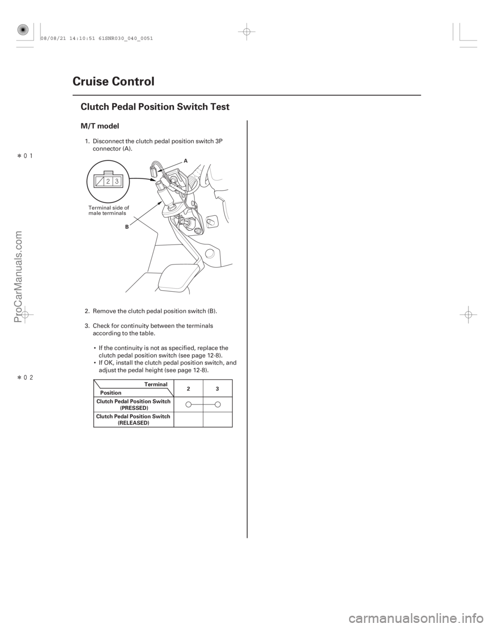
M/T model
4-50Cruise Control
Clutch Pedal Position Switch Test
A
B
Terminal
Position
Clutch Pedal Position Switch 3
2
(PRESSED)
Clutch Pedal Position Switch (RELEASED)
1. Disconnect the clutch pedal position switch 3P
connector (A).
2. Remove the clutch pedal position switch (B).
3. Check for continuity between the terminals accordingtothetable.
If the continuity is not as specified, replace the clutch pedal position switch (see page 12-8).
If OK, install the clutch pedal position switch, and adjust the pedal height (see page 12-8).
Terminal side of
male terminals
08/08/21 14:10:51 61SNR030_040_0051
ProCarManuals.com
DYNOMITE -2009-
Page 104 of 2893
����
���
����
�
��
5-5
A
B
A
B
15. Disconnect the evaporative emission (EVAP)
canister hose (A) and the brake booster vacuum
hose (B).
16. Remove the quick-connect fitting cover (A), then disconnect the fuel feed hose (B) (see page 11-329).
17. M/T model: Remove the shift cables. Do not bend the cables excessively (see step 7 on page 13-8).
18. M/T model: Remove the clutch slave cylinder, and the clutch line bracket mounting bolt (see step 5 on
page 13-7). 19. M/T model: Remove the air cleaner bracket.
20. Remove the drive belt (see page 4-31).
21. Remove the idler pulley base (see step 2 on page
4-32).
22. Wait until the engine is cool, then carefully remove the radiator cap.
23. Raise the vehicle on the lift.
24. Remove the front wheels.
25. Remove the splash shield.
26. Loosen the drain plug in the radiator, and drain the engine coolant (see page 10-8).
(cont’d)
08/08/21 14:20:23 61SNR030_050_0005
ProCarManuals.com
DYNOMITE -2009-
Page 106 of 2893
�
��
�
���
��
����
5-7
A
B VSB02C000015
40. Disconnect the A/C compressor clutch connector(A), then remove the A/C compressor (B) without
disconnecting the A/C hoses.
41. Lower the vehicle on the lift.
42. Remove the radiator (see page 10-19).
43. A/T model: Disconnect the automatic transmission fluid (ATF) cooler hoses from the transmission,
then plug the lines and hoses. 44. Disconnect the heater hoses.
45. Install the bulkhead (see step 13 on page 10-21).
46. Attach the engine hanger adapter (VSB02C000015)
to the threaded hole in the cylinder head.
(cont’d)
08/08/21 14:20:25 61SNR030_050_0007
ProCarManuals.com
DYNOMITE -2009-
Page 118 of 2893
����
�
���
��
�
��
5-19
A
12x1.25mm
64 N·m
(6.5 kgf·m, 47 lbf·ft) 12x1.25mm
64 N·m
(6.5 kgf·m, 47 lbf·ft)
B A
8x1.25mm
22 N·m
(2.2 kgf·m, 16 lbf·ft)
22. M/T model: Loosely tighten the new front mount
mounting bolt (A).
23. Lower the vehicle on the lift.
24. Remove the engine support hanger and the engine hanger adapter from the engine and the vehicle.
25. Tighten the upper torque rod mounting bolt. 26. Raise the vehicle on the lift.
27. M/T model: Tighten the front mount mounting bolt.
28. Install the A/C compressor (A), then connect the
A/C compressor clutch connector (B).
(cont’d)
Replace.
08/08/21 14:20:33 61SNR030_050_0019
ProCarManuals.com
DYNOMITE -2009-
Page 120 of 2893
����
���������
����
5-21
A AB
B 6x1.0mm
10 N·m
(1.0 kgf·m, 7.2 lbf·ft)
A B
41. Lower the vehicle on the lift.
42. Connect the heater hoses.
43. A/T model: Connect the automatic transmissionfluid (ATF) cooler hoses (A) to the transmission,
and secure the hoses with the clips (B) (see page
14-253).
44. Remove the bulkhead, then install the radiator (see page 10-19).
45. Install the idler pulley base (see step 2 on page 4-34).
46. Install the drive belt (see page 4-31). 47. M/T model: Install the air cleaner bracket.
48. M/T model: Install the shift cables (see step 37 on
page 13-20).
49. M/T model: Install the clutch slave cylinder and the clutch line bracket mounting bolt (see step 40 on
page 13-21).
50. Connect the fuel feed hose (A) (see page 11-331), then install the quick-connect fitting cover (B).
(cont’d)
08/08/21 14:20:59 61SNR030_050_0021
ProCarManuals.com
DYNOMITE -2009-
Page 226 of 2893
����
�������
����
7-12Engine Block
Oil Pan Removal (cont’d)
B
A
19. A/T model: Remove the shift cable cover.
20. K20Z2 engine: Remove the torque converter cover/clutch cover. 21. K20Z3 engine: Remove the clutch cover (A) and the
transmission mounting bolts (B).
22. Remove the bolts securing the oil pan.
23. Using a flat blade screwdriver, separate the oil pan from the lower block in the places shown.
24. Remove the oil pan.
08/08/21 14:32:35 61SNR030_070_0012
ProCarManuals.com
DYNOMITE -2009-
Page 227 of 2893
���
����
����
�(�#�'�����������
�����
��������������� �����)����
7-13
Crankshaft and Piston Removal
1. Remove the engine/transmission (see page 5-3).
2. Remove the transmission: Manual transmission (see page 13-7)
Automatic transmission (see page 14-233)
3. M/T model: Remove the pressure plate (see page 12-19), the clutch disc (see page 12-20), and the
flywheel (see page 12-21).
4. A/T model: Remove the drive plate (see page 14-242).
5. Remove the oil pan (see page 7-11).
6. Remove the oil pump (see page 8-16).
7. Remove the cylinder head (see page 6-38).
8. Remove the baffle plates. 9. Remove the 8 mm bolts in sequence.
10. Remove the bearing cap bolts. To prevent warpage, loosen the bolts in sequence 1/3 turn at a time;
repeat the sequence until all bolts are loosened.
(cont’d)
08/08/21 14:32:35 61SNR030_070_0013
ProCarManuals.com
DYNOMITE -2009-