Page 1666 of 2893
����
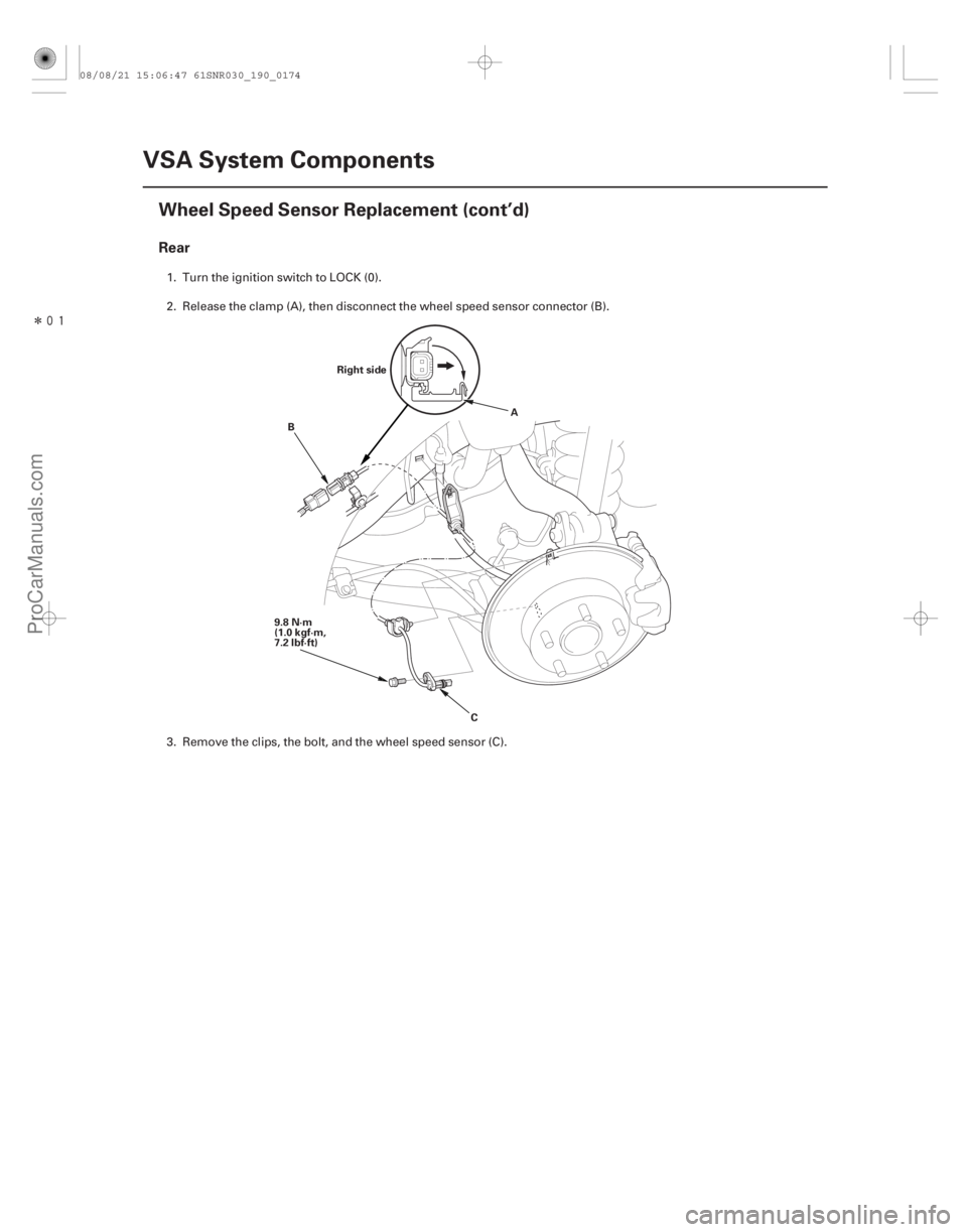
Rear
19-174VSA System Components
Wheel Speed Sensor Replacement (cont’d)
Right side
9.8 N·m
(1.0 kgf·m,
7.2 lbf·ft) A
B
C
1. Turn the ignition switch to LOCK (0).
2. Release the clamp (A), then disconnect the wheel speed sensor connector (B).
3. Remove the clips, the bolt, and the wheel speed sensor (C).
08/08/21 15:06:47 61SNR030_190_0174
ProCarManuals.com
DYNOMITE -2009-
Page 1667 of 2893
 and the sensor hole in the knuckle
(B).
5. Insert the guide pin to")
�����
����������
19-175
A
B
A
07AAG-SVBA100 B
07AAG-SVBA100
A
4. Apply multi-purpose grease to the wheel speedsensor O-ring (A) and the sensor hole in the knuckle
(B).
5. Insert the guide pin tool (A) into the wheel speed sensor bolt hole until the shoulder of the tool
contacts the wheel speed sensor bracket.
NOTE: To prevent O-ring damage, the wheel speed
sensor must be installed with the guide pin tool. 6. Insert the wheel speed sensor (A) and the guide pin
tool (B) into the bolt hole on the knuckle.
NOTE: To ensure proper alignment when pushing
the wheel speed sensor into the knuckle housing,
do not hold the sensor bracket during installation,
hold the sensor wire.
7. Gently push and pull the wheel speed sensor in and out to make sure the O-ring is sliding properly in its
housing. While you are doing this, make sure the
sensor doesn’t come out of the knuckle assembly. If
the sliding effort is too high, remove the wheel
speed sensor, inspect the O-ring for damage, and
start the installation process again.
8. Remove the guide pin tool, then install the bolt, and tighten it to specified torque.
9. Clean the mating surfaces between the brake disc and the inside of the wheel, then install the front
wheel.
10. Start the engine, and make sure the ABS and the VSA indicators go off.
11. Test-drive the vehicle, and make sure the ABS and the VSA indicators do not come on.
08/08/21 15:06:48 61SNR030_190_0175
ProCarManuals.com
DYNOMITE -2009-
Page 1791 of 2893
����
S
pecial Tools Required
20-114 Dashboard
Dashboard/Steering Hanger Beam Disassembly/Reassembly
Fastener Locations
:Bolt,5
5x0.8mm
5N·")
���
����
���
�(�#�'���������������������������������"�����)����
S
pecial Tools Required
20-114 Dashboard
Dashboard/Steering Hanger Beam Disassembly/Reassembly
Fastener Locations
:Bolt,5
5x0.8mm
5N·m
(0.5 kgf·m,
4lbf·ft) A
B
B C
D
A D
KTC trim tool set SOJATP2014
NOTE:
Put on gloves to protect your hands.
Take care not to scratch the dashboard and related parts.
Take care not to bend the brackets.
Use the appropriate tool from the KTC trim tool set to avoid damage when removing components.
1. Remove the dashboard/steering hanger beam (see page 20-108).
2. Remove these items from the dashboard: Instrument panel (see page 20-98)
Gauge control module (speedo) trim (see page20-99)
Subdisplay visor (see page 20-100)
Navigation unit, with navigation system – ’06-08 models (see page 23-155)
– ’09 model (see page 23-355)
Audio unit, without navigation system – ’06-08 models (see page 23-80)
– ’09 model (see page 23-256)
Passenger’s airbag (see page 24-189)
Gauge control module (speedo) (see page 22-277)
Gauge control module (tach) (see page 22- 277)
3. Remove the bolts. 4
. From the back of the dashboard, release the hooks
(A), then remove the center joint duct (B).
5. From the back of the dashboard, disconnect the tweeter connectors (A), the front accessory power
socket connector (B), and the sunlight sensor
connector (C), then detach the harness clips (D).
08/08/21 15:03:00 61SNR030_200_0116
ProCarManuals.com
DYNOMITE -2009-
Page 1796 of 2893
����
��������
����
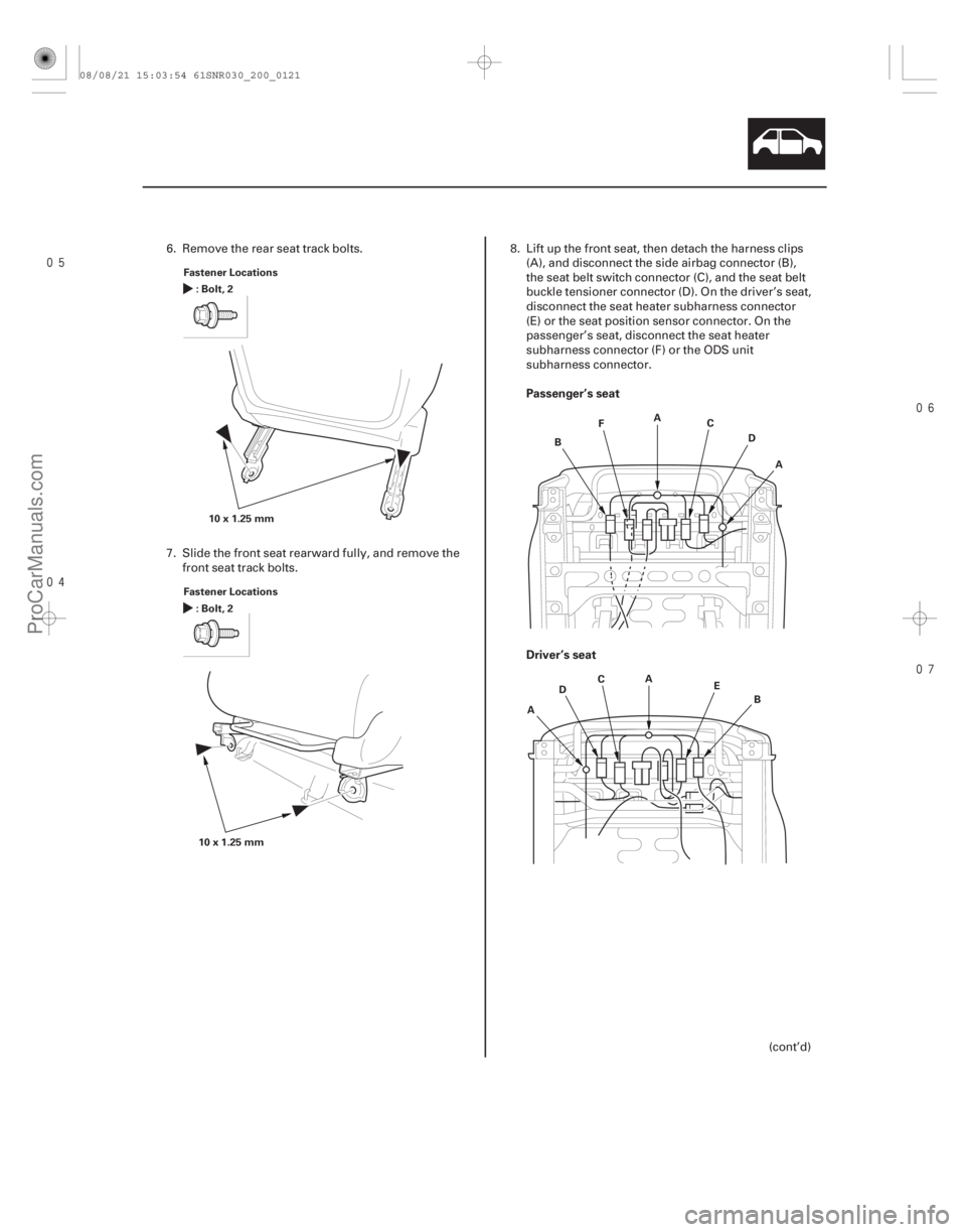
Passenger’s seat
Driver’s seat
20-119
Fastener Locations
:Bolt,2
10x1.25mm
Fastener Locations :Bolt,2
10x1.25mm A
B C
D
F
A
A B
C
D E
A
6. Remove the rear seat track bolts.
7. Slide the front seat rearward fully, and remove the
front seat track bolts. 8. Lift up the front seat, then detach the harness clips
(A), and disconnect the side airbag connector (B),
the seat belt switch connector (C), and the seat belt
buckle tensioner connector (D). On the driver’s seat,
disconnect the seat heater subharness connector
(E) or the seat position sensor connector. On the
passenger’s seat, disconnect the seat heater
subharness connector (F) or the ODS unit
subharness connector.
(cont’d)
08/08/21 15:03:54 61SNR030_200_0121
ProCarManuals.com
DYNOMITE -2009-
Page 1797 of 2893
�
��
Passenger’s Seat
20-12020-120 Seats
Front Seat Removal/Installation
(cont’d)
Front Seat Frame Replacement
Fastener Locations
:Bolt,4
10x")
���
���
�(�#�'���������������
����������������� �����)�
��
Passenger’s Seat
20-12020-120 Seats
Front Seat Removal/Installation
(cont’d)
Front Seat Frame Replacement
Fastener Locations
:Bolt,4
10x1.25mm
34 N·m
(3.5 kgf·m, 25 lbf·ft) A
A
B
C
Fastener Locations
:Clip,4
A
9. With the help of an assistant, carefully remove thefront seat through the front door opening.
10. Install the seat in the reverse order of removal, and note these items:
Apply medium strength liquid thread lock to the seat mounting bolts before reinstallation.
Tighten the seat mounting bolts to the specified torque in the sequence shown. Slide the seat (A)
all the way back and tighten and , then slide
it forward and tighten and . The driver’s seat
is shown; the passenger’s seat is similar.
Tighten the bolts by hand first, then tighten them to specification with a torque wrench.
Make sure each connector is plugged in properly.
Check for any DTCs that may have been set during repairs, and clear them.
Do the battery terminal reconnection procedure (see page 22-68). Calibrate the ODS unit after any of these actions
(see page 24-27):
Front passenger’s seat replacement (including any seat components)
Replacement of the front seat weight sensors
After a vehicle collision
NOTE: Put on gloves to protect your hands.
Apply oil to the pivot portions of the slide locks.
Apply multipurpose grease to the sliding portions of the seat tracks.
If the side airbag has deployed, replace the seat frame and related pieces with new ones (see page
24-185).
1. Remove the front seat (see page 20-118).
2. Remove these items: Front seat-back cover (see page 20-123)
Front seat cushion cover (see page 20-127)
ODS unit (see page 24-209)
Front seat belt buckle (see page 24-6)
3. Remove the clips, then remove the recline inner covers (A) and module holder (B) from the seat
frame (C).
08/08/21 15:03:55 61SNR030_200_0122
ProCarManuals.com
DYNOMITE -2009-
Page 1798 of 2893
�
��
Passenger’s Seat
20-12020-120 Seats
Front Seat Removal/Installation
(cont’d)
Front Seat Frame Replacement
Fastener Locations
:Bolt,4
10x")
���
���
�(�#�'���������������
����������������� �����)�
��
Passenger’s Seat
20-12020-120 Seats
Front Seat Removal/Installation
(cont’d)
Front Seat Frame Replacement
Fastener Locations
:Bolt,4
10x1.25mm
34 N·m
(3.5 kgf·m, 25 lbf·ft) A
A
B
C
Fastener Locations
:Clip,4
A
9. With the help of an assistant, carefully remove thefront seat through the front door opening.
10. Install the seat in the reverse order of removal, and note these items:
Apply medium strength liquid thread lock to the seat mounting bolts before reinstallation.
Tighten the seat mounting bolts to the specified torque in the sequence shown. Slide the seat (A)
all the way back and tighten and , then slide
it forward and tighten and . The driver’s seat
is shown; the passenger’s seat is similar.
Tighten the bolts by hand first, then tighten them to specification with a torque wrench.
Make sure each connector is plugged in properly.
Check for any DTCs that may have been set during repairs, and clear them.
Do the battery terminal reconnection procedure (see page 22-68). Calibrate the ODS unit after any of these actions
(see page 24-27):
Front passenger’s seat replacement (including any seat components)
Replacement of the front seat weight sensors
After a vehicle collision
NOTE: Put on gloves to protect your hands.
Apply oil to the pivot portions of the slide locks.
Apply multipurpose grease to the sliding portions of the seat tracks.
If the side airbag has deployed, replace the seat frame and related pieces with new ones (see page
24-185).
1. Remove the front seat (see page 20-118).
2. Remove these items: Front seat-back cover (see page 20-123)
Front seat cushion cover (see page 20-127)
ODS unit (see page 24-209)
Front seat belt buckle (see page 24-6)
3. Remove the clips, then remove the recline inner covers (A) and module holder (B) from the seat
frame (C).
08/08/21 15:03:55 61SNR030_200_0122
ProCarManuals.com
DYNOMITE -2009-
Page 1799 of 2893
��������
20-121
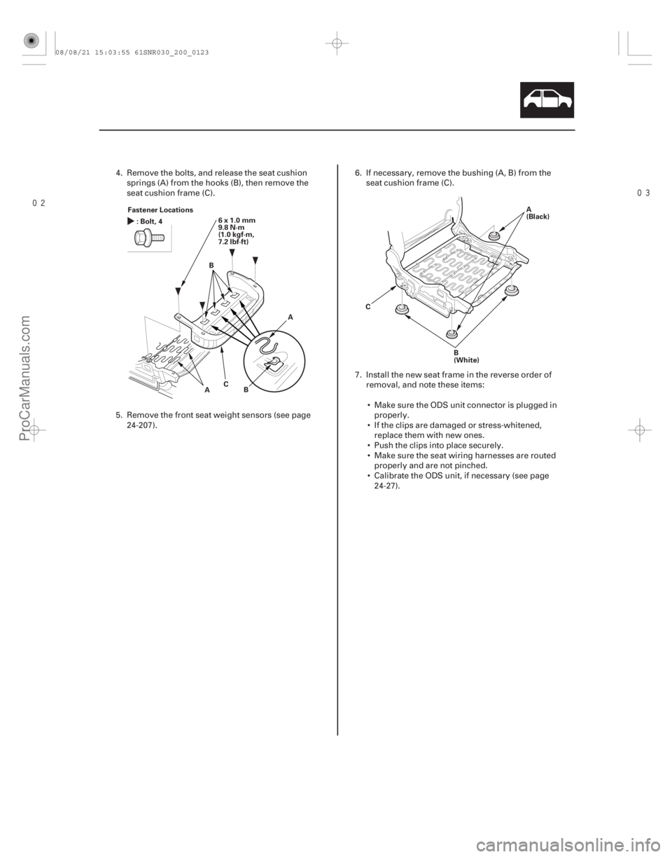
Fastener Locations
6x1.0mm
9.8 N·m
(1.0 kgf·m,
7.2 lbf·ft)
:Bolt,4
AB
C A
B
C A
(Black)
B
(White)
4. Remove the bolts, and release the seat cushion springs (A) from the hooks (B), then remove the
seat cushion frame (C).
5. Remove the front seat weight sensors (see page 24-207). 6. If necessary, remove the bushing (A, B) from the
seat cushion frame (C).
7. Install the new seat frame in the reverse order of removal, and note these items:
Make sure the ODS unit connector is plugged in properly.
If the clips are damaged or stress-whitened, replace them with new ones.
Push the clips into place securely.
Make sure the seat wiring harnesses are routed properly and are not pinched.
Calibrate the ODS unit, if necessary (see page 24-27).
08/08/21 15:03:55 61SNR030_200_0123
ProCarManuals.com
DYNOMITE -2009-
Page 1800 of 2893
����
Driver’s Seat
20-122 Seats
Front Seat Frame Replacement (cont’d)
A
B
C
D
Fastener Locations
:Clip,3
A
E
Check the operation of the driver’")
����
�(�#�'���������������
����������������� �����)����
Driver’s Seat
20-122 Seats
Front Seat Frame Replacement (cont’d)
A
B
C
D
Fastener Locations
:Clip,3
A
E
Check the operation of the driver’s seat position sensor
after any of these actions (see page 24-29):
Driver’s seat position sensor replacement
Cover plate (front side of driver’s seat slide rail) replacement
NOTE: Put on gloves to protect your hands.
Apply oil to the pivot portions of the slide lock.
Apply multipurpose grease to the sliding portions and pivot portions of the seat tracks.
If the side airbag has deployed, replace the seat frame and related pieces with new ones (see page
24-185).
1. Remove the front seat (see page 20-118).
2. Remove these items: Front seat-back cover/pad (see page 20-123)
Front seat cushion cover/pad (see page 20-127)
Driver’s seat position sensor (see page 24-211)
Front seat belt buckle (see page 24-6) 3. Remove the clips, then remove the recline inner
covers (A), the outer upper rail cover (B), the inner
upper rail cover (C) and the module holder (D) from
the seat frame (E).
4. Install the new seat frame in the reverse order of removal, and note these items:
Make sure the driver’s seat position sensor connector is plugged in properly.
If the clips are damaged or stress-whitened, replace them with new ones.
Push the clips into place securely.
Make sure the seat wiring harnesses are routed properly and not pinched.
08/08/21 15:03:56 61SNR030_200_0124
ProCarManuals.com
DYNOMITE -2009-