Page 1652 of 2893
����
�µ
�µ
�µ
�µ
DTC 86-71:
YES
NO Sign
YES
NO
VSA Modulator- control Unit 37P
Connector Terminal Yaw Rate-lateral
Acceleration Sensor 5P Connect")
���
�(�#�'��������� �����
�������'�������
�������)����
�µ
�µ
�µ
�µ
DTC 86-71:
YES
NO Sign
YES
NO
VSA Modulator- control Unit 37P
Connector Terminal Yaw Rate-lateral
Acceleration Sensor 5P ConnectorTerminal
19-160VSA System Components
DTC Troubleshooting (cont’d)
VSA MODULATOR-CONTROL UNIT 37P CONNECTOR
CAN-L (RED)
CAN-L (RED)
CAN-H (WHT) CAN-H (WHT)
YAW RATE-LATERAL ACCELERATION
SENSOR 5P CONNECTOR
F-CAN Communication with Yaw
Rate-Lateral Acceleration Sensor Malfunction
1. Turn the ignition switch to ON (II).
2. Clear the DTC with the HDS.
3. Turn the ignition switch to LOCK (0), then turn it to
ON (II) again.
4. Check for DTCs with the HDS.
If DTC 86-01 is indicated at the same time, do
the DTC 86-01 troubleshooting first (see page
19-156). If DTC 86-01 is not indicated, go to step 5.
If any other DTCs are indicated, go to the
indicated DTCs troubleshooting. If DTCs are not
indicated, there was an intermittent failure, the
system is OK at this time. Check for loose terminals
at the yaw rate-lateral acceleration sensor 5P
connector and the VSA modulator-control unit 37P
connector. Refer to intermittent failures
troubleshooting (see page 19-98).
5. Turn the ignition switch to LOCK (0).
6. Disconnect the yaw rate-lateral acceleration sensor 5P connector (see page 19-169).
7. Disconnect the VSA modulator-control unit 37P connector (see step 2 on page 19- 171).8. Check for continuity between the VSA modulator-
control unit 37P connector terminal and the yaw
rate-lateral acceleration sensor 5P connector
terminal (see table).
CAN-L No. 1 No. 4
CAN-H No. 15 No. 3
Go to step 9.
Repair open in the wire between the yaw rate-
lateral acceleration sensor and the VSA modulator-
control unit.
Wire side of female terminals
Wire side of female terminalsIs DTC 86-71 indicated?
Is there continuity?
08/08/21 15:06:43 61SNR030_190_0160
ProCarManuals.com
DYNOMITE -2009-
Page 1653 of 2893
.
10. Me")
��������
�µ
�µ
�µ
�µ
YES
NO
YES
NO
19-161
YAW RATE-LATERAL ACCELERATION SENSOR
5P CONNECTOR
YEL YAW RATE-LATERAL ACCELERATION SENSOR
5P CONNECTOR
BLK
9. Turn the ignition switch to ON (II).
10. Measure the voltage between yaw rate-lateral acceleration sensor 5P connector terminal No. 1
and body ground.
Go to step 11.
Check the No. 4 (7.5 A) fuse in the under-dash
fuse/relay box. If the fuse is OK, repair open in the
wirebetweentheNo.4(7.5A)fuseandyawrate-
lateral acceleration sensor. 11. Turn the ignition switch to LOCK (0).
12. Reconnect the yaw rate-lateral acceleration sensor
5P connector.
13. Turn the ignition switch to ON (II).
14. Measure the voltage between yaw rate-lateral acceleration sensor 5P connector terminal No. 5
and body ground.
Replace the yaw rate-lateral acceleration
sensor (see page 19-169).
Repair open in the wire between the yaw rate-
lateral acceleration sensor and body ground
(G602).
Wire side of female terminals
Wire side of female terminals
Is there battery voltage?Is t her e 0.1 V or l ess?
08/08/21 15:06:43 61SNR030_190_0161
ProCarManuals.com
DYNOMITE -2009-
Page 1654 of 2893
�����(�#���������� �����
�������(�������
�������)����
�µ
�µ �µ
�µ
�µ
�µ
DTC 107-22: DTC 108-21:
YES
NO YES
NO
YES
NO
19-16219-162VSA System Compone")
�(�#�'��������� �����
�������(���������������)�����(�#�'��������� �����
�������(�������
�������)����
�µ
�µ �µ
�µ
�µ
�µ
DTC 107-22: DTC 108-21:
YES
NO YES
NO
YES
NO
19-16219-162VSA System Components
DTC Troubleshooting (cont’d)
Central Processing Unit (CPU)
Internal Circuit Malfunction Steering Angle Sensor
Malfunction
1. Turn the ignition switch to LOCK (0) to cool the VSA
modulator-control unit, and wait 1 hour or more.
2. Turn the ignition switch to ON (II).
3. Clear the DTC with the HDS.
4. Turn the ignition switch to LOCK (0), then turn it to ON (II) again.
5. Check for DTCs with the HDS.
Replace the VSA modulator-control unit
(see page 19-171).
The system is OK at this time. 1. Turn the ignition switch to ON (II).
2. Clear the DTC with the HDS.
3. Test-drive the vehicle.
NOTE: Drive the vehicle on the road, not on a lift.
4. Check for DTCs with the HDS.
Go to step 5.
Intermittent failure, the system is OK at this
time.
5. Turn the ignition switch to LOCK (0).
6. Substitute a known-good steering angle sensor (see page 19-168).
7. Turn the ignition switch to ON (II).
8. Clear the DTC with the HDS.
9. Test-drive the vehicle. NOTE: Drive the vehicle on the road, not on a lift.
10. Check for DTCs with the HDS.
Replace the VSA modulator-control unit
(see page 19-171).
Replace the original steering angle sensor
(see page 19-168).
I s DT C 107 -22 i nd i cat ed ? I s DT C 108-21 i nd i cat ed ?
I s DT C 108-21 i nd i cat ed ?
08/08/21 15:06:43 61SNR030_190_0162
ProCarManuals.com
DYNOMITE -2009-
Page 1658 of 2893
����
�µ
�µ
�µ
�µ �µ
�µ
�µ
�µ
ABS indicator, brake system indicator, and
VSA indicator do not go off
YES
NO
YES
NO YES
NO
YES
NO
19-")
����
�����
�(�#�'���������������
�����������������������)����
�µ
�µ
�µ
�µ �µ
�µ
�µ
�µ
ABS indicator, brake system indicator, and
VSA indicator do not go off
YES
NO
YES
NO YES
NO
YES
NO
19-166
VSA System Components
Symptom Troubleshooting (cont’d)
VSA MODULATOR-CONTROL UNIT 37P CONNECTOR
IG1 (GRY) VSA MODULATOR-CONTROL UNIT 37P CONNECTOR
IG1 (GRY)
1. Turn the ignition switch to LOCK (0).
2. Check the No. 4 (7.5 A) fuse in the under-dash fuse/relay box.
Go to step 3.
Reinstall the checked fuse, then go to step 9.
3. Disconnect the VSA modulator-control unit 37P connector (see step 2 on page 19- 171).
4. Disconnect the yaw rate-lateral acceleration sensor 5P connector (see page 19- 169).
5. Check for continuity between VSA modulator- control unit 37P connector terminal No. 28 and
body ground.
Repair short to body ground in the wire
between the No. 4 (7.5 A) fuse in the under-dash
fuse/relay box and the VSA modulator-control unit
or the yaw rate-lateral acceleration sensor.
Install a new No. 4 (7.5 A) fuse in the under-
dashfuse/relaybox,thengotostep6. 6. Reconnect all connectors.
7. Turn the ignition switch to ON (II).
8. Check the ABS indicator, the brake system
indicator and the VSA indicator for several seconds
when the ignition switch is tuned to ON (II).
Troubleshooting is complete.
Replace the VSA modulator-control unit
(see page 19-171).
9. Disconnect the VSA modulator-control unit 37P connector (see step 2 on page 19-171).
10. Turn the ignition switch to ON (II).
11. Measure the voltage between VSA modulator- control unit 37P connector terminal No. 28 and
body ground.
Go to step 12.
Repair open in the wire between the No. 4
(7.5 A) fuse in the under-dash fuse/relay box and
the VSA modulator-control unit.
12. Turn the ignition switch to LOCK (0).
Wire side of female terminals Wire side of female terminals
Isthefuseblown?
Is there continuity? Does t he i nd i cat or s come on t hen go of f ?
Is there battery voltage?
08/08/21 15:06:44 61SNR030_190_0166
ProCarManuals.com
DYNOMITE -2009-
Page 1660 of 2893
����
19-168VSA System Components
Steering Angle Sensor Replacement
A
B
C
NOTE: Do not damage or drop the combination switch as the steering angle sens")
���
�(�#�'���������������
���������������
� �����)����
19-168VSA System Components
Steering Angle Sensor Replacement
A
B
C
NOTE: Do not damage or drop the combination switch as the steering angle sensor is sensitive to shock and vibration.
1. With the wheels in the straight-ahead position and the steering wheel centered, remove the steering wheel (see page 17-6).
2. Remove the steering column covers (see page 17-9) and the cable reel (see page 24-200).
3. Remove the combination switch assembly (see step 11 on page 17-11).
4. Remove the combination light switch (A) and the wiper/washer switch (B) from the combination switch body assembly (C).
5. Install the combination switch body assembly in the r everse order of removal.
NOTE: Do not remove the steering angle sensor from the combination switch body.
When installing the cable reel, set the turn signal canceling sleeve position so that the arrow points straight up (see page 24-201).
When installing the combination switch, tighten the m ounting screws to the specified torque and sequence
shown (see page 17-12).
08/08/21 15:06:45 61SNR030_190_0168
ProCarManuals.com
DYNOMITE -2009-
Page 1661 of 2893
���� ���
�(�#����������������
�����������������������)���
19-16919-169
Yaw Rate-Lateral Acceleration
Sensor Replacement VSA Sensor Neutral Position")
���
�(�#�'���������������
�������������
�
� �����)���� ���
�(�#�'���������������
�����������������������)���
19-16919-169
Yaw Rate-Lateral Acceleration
Sensor Replacement VSA Sensor Neutral Position
Memorization
AB
9.8 N·m
(1.0 kgf·m, 7.2 lbf·ft) A
NOTE:
Do not damage or drop the sensor as it is sensitive.
Do not use power tools when replacing the sensor.
1. Turn the ignition switch to LOCK (0).
2. Remove the center console (see page 20-92).
3. Remove the yaw rate-lateral acceleration sensor (A) mounting bolts.
4. Pull out the yaw rate-lateral acceleration sensor, then disconnect the sensor connector (B).
5. Install the yaw rate-lateral acceleration sensor in the reverse order of removal.
6. Do the VSA sensor neutral position memorization (see page 19-169). NOTE: Do not press the brake pedal during this
procedure.
1. Park the vehicle on a flat and level surface, with the steering wheel in the straight ahead position.
2. With the ignition switch in LOCK (0), connect the HDS to the data link connector (DLC) (A) under the
driver’s side of the dashboard.
3. Turn the ignition switch to ON (II).
4. Make sure the HDS communicates with the vehicle and the VSA modulator-control unit. If it doesn’t
troubleshoot the DLC circuit (see page 11-204).
5. Select VSA ADJUSTMENT with the HDS, and follow the screen prompts.
NOTE: See the HDS Help menu for specific
instructions.
6. Turn the ignition switch to LOCK (0).
08/08/21 15:06:46 61SNR030_190_0169
ProCarManuals.com
DYNOMITE -2009-
Page 1664 of 2893

1. Install the VSA modulator-control unit onto the bracket.
2. Install the bracket with the VSA")
Installation
19-172VSA System Components
VSA Modulator-Control Unit Removal and Installation (cont’d)
1. Install the VSA modulator-control unit onto the bracket.
2. Install the bracket with the VSA modulator-control unit to the body.
3. Reconnect the six brake lines, then tighten the flare nuts to the specified torque.
4. Align the connecting surface of the VSA modulator-control unit 37P connector to the VSA modulator-control unit.
5. Pull up the lever of the VSA m
odulator-control unit 37P connector, then confirm the connector is fully seated.
6. Bleed the brake system (see page 19-9).
7. Do the VSA sensor neutral position memorization (see page 19-169).
8. Start the engine, and make sure the ABS and the VSA indicators go off.
9. Test-drive the vehicle, and make sure the ABS, and the VSA indicators do not come on. NOTE: If the brake pedal is spongy, there may be air trapped in the modulator which could then be induced into
the normal brake system during modulation. Bleed the brake system again (see page 19-9).
08/08/21 15:06:47 61SNR030_190_0172
ProCarManuals.com
DYNOMITE -2009-
Page 1665 of 2893
���
�(�#�'���������������
���������������
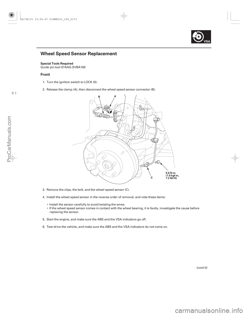
� �����)���� Special Tools Required
Front
19-173
Wheel Speed Sensor Replacement
A
B
C9.8 N·m
(1.0 kgf·m,
7.2 lbf·ft)
Guide pin tool 07AAG-SVBA100
1. Turn the ignition switch to LOCK (0).
2. Release the clamp (A), then disconnect the wheel speed sensor connector (B).
3. Remove the clips, the bolt, and the wheel speed sensor (C).
4. Install the wheel speed sensor in the reverse order of removal, and note these items: Install the sensor carefully to avoid twisting the wires.
If the wheel speed sensor comes in contact with the wheel bearing, it is faulty, investigate the cause beforereplacing the sensor.
5. Start the engine, and make sure the ABS and the VSA indicators go off.
6. Test-drive the vehicle, and make sure the ABS and the VSA indicators do not come on.
(cont’d)
08/08/21 15:06:47 61SNR030_190_0173
ProCarManuals.com
DYNOMITE -2009-