Page 2144 of 2893
�
�
22-194Interior Lights
Circuit Diagram
D A
B
A C
GRNMICU
UNDER-DASH FUSE/RELAY BOX
GRNE37 E3
LT GRN BRNE17 E2
GRYK4
(8 W) (8 W)
1
(Without moon")
������(�#�'���������������������������������������)�
�
22-194Interior Lights
Circuit Diagram
D A
B
A C
GRNMICU
UNDER-DASH FUSE/RELAY BOX
GRNE37 E3
LT GRN BRNE17 E2
GRYK4
(8 W) (8 W)
1
(Without moonroof)
LT BLU
PNKDOOR
OFF
PNK
BLU
3
LT BLU LT BLU
LT BLU
(With moonroof)
1
2
(8 W) (8 W)
PNK 1
ON OFF
(8 W) RED
UNDER-HOOD FUSE/RELAY BOX
No. 22 (7.5 A)
No. 1 (BAT) (100 A)
BATTERY
CEILING
LIGHT
INTERIOR
LIGHT SWITCH
(In the moonroof
switch)
RIGHT REAR
DOOR
SWITCH
(Closed:
Door open)
LEFT REAR
DOOR
SWITCH
(Closed:
Door open)
FRONT
PASSENGER’S
DOOR SWITCH
(Closed:
Door open)
DRIVER’S
DOOR
SWITCH
(Closed:
Door open) D2
1 1
1
9*2 8*1
1*1
7*2 LT BLU
LT BLU
FRONT
PASSENGER’S
DOOR
COURTESY
LIGHT LT BLU
VANITY
MIRROR
LIGHTS *2
No. 22 (7.5 A)FUSE
(UNDER-HOOD
FUSE/RELAY BOX) LT BLU
GRN (3.4 W)
DRIVER’S
DOOR
COURTESY
LIGHT
GRN1 No. 22 (7.5 A)FUSE
(UNDER-HOOD
FUSE/RELAY BOX)
LT GRN
GRN (3.4 W)
FRONT
PASSENGER’S
DOOR
COURTESY
LIGHT BLU
BLK 3
2
G701 E36
BLU TRUNK LID
LATCH
SWITCH
(Closed:
Trunk lid open)BLU
TRUNK
LIGHT
FRONT
INDIVIDUAL
MAP LIGHTS
FRONT
INDIVIDUAL
MAP LIGHTS
08/08/21 14:27:49 61SNR030_220_0196
ProCarManuals.com
DYNOMITE -2009-
Page 2145 of 2893

LT BLU
BLK GRY
GRY GRY
RED
(5 W)
1
WHT
2
(LED)
GRN
G502 AMBIENT
LIGHT
DASH LIGHTS
BRIGHTNESS
CONTROLLER TRUNK
LIGHT
UNDER-DASH")
�����
�µ
�µ
�µ
�µ
22-195
R10LT BLU
K5
G3
E38
CLOSE OPEN
1
2 (3.4 W)
LT BLU
BLK GRY
GRY GRY
RED
(5 W)
1
WHT
2
(LED)
GRN
G502 AMBIENT
LIGHT
DASH LIGHTS
BRIGHTNESS
CONTROLLER TRUNK
LIGHT
UNDER-DASH
FUSE/RELAY BOX
No. 14 (7.5 A) FUSE
(UNDER-DASH
FUSE/RELAY BOX) GLOVE
BOX
LIGHTGLOVE
BOX
LID
GRY
(LED)
RED 2 1
DRIVER’S
FOOTWELL
LIGHT
DASH LIGHTS
BRIGHTNESS
CONTROLLER
GRY
(TYPE S model)
BLU
DRIVER’S
DOOR
COURTESY
LIGHT
TRUNK LID
LATCH
SWITCH
GRY(LED)
RED 2 1
FRONT
PASSENGER’S
FOOTWELL
LIGHT
DASH LIGHTS
BRIGHTNESS
CONTROLLER
LT BLU
DRIVER’S
VANITY
MIRROR
LIGHT
SWITCH
DRIVER’S
VANITY
MIRROR
LIGHT (2 W)DRIVER’S
SUNVISOR
1
2 LT BLU
PASSENGER’S
VANITY
MIRROR
LIGHT
SWITCH
PASSENGER’S
VANITY
MIRROR
LIGHT (2 W)PASSENGER’S
SUNVISOR
1
2
G502 BLK *2
BLK BLK
No. 22 (7.5 A) FUSE
(UNDER-HOOD
FUSE/RELAY BOX)
C
D B
5*3
4*4
3*2
2*2
5*4
3*3 *1: ’06 07 models
*2: ’08 09 models
*3: ’06 07 models with moonroof
*4: ’06 07 models without moonroof
08/08/21 14:27:49 61SNR030_220_0197
ProCarManuals.com
DYNOMITE -2009-
Page 2149 of 2893
���� ���
�(�#����������������������������
���
�������)����
Glove Box Light: 3.4 W
Vanity Mirror Light: 2 W
’08-09 models
22-19922-199
Glove Box Li")
���
�(�#�'���������������������������
�
�
�������)���� ���
�(�#�'���������������������������
���
�������)����
Glove Box Light: 3.4 W
Vanity Mirror Light: 2 W
’08-09 models
22-19922-199
Glove Box Light Test/Replacement Vanity Mirror Light Test/Replacement
B
A C
A B
C
1. Open the glove box.
2. Remove the screws, then disconnect the 2P
connector from the glove box light (A).
3. Check for continuity between terminals No. 1 and No. 2.
There should be continuity with the switch (B) released.
There should be no continuity with the switch (B) pushed.
4. If the continuity is not as specified, check the bulb (C). If the bulb is OK, replace the light.
5. Install the glove box light in the reverse order of removal. 1. Open the sunvisor.
2. Remove the sunvisor (see page 20-84).
3. Disconnect the 2P connector (A) from the vanity
mirror light.
4. Check for continuity between terminals No. 1 and No. 2.
With the vanity mirror cover (B) opened, there should be continuity.
With the vanity mirror cover closed, there should be no continuity.
5. If the continuity is not as specified, replace the bulb (C) or the sunvisor.
6. Install the vanity mirror light in the reverse order of removal.
08/08/21 14:27:51 61SNR030_220_0201
ProCarManuals.com
DYNOMITE -2009-
Page 2254 of 2893
�����
������(�#�'�������������������������������
�������)����
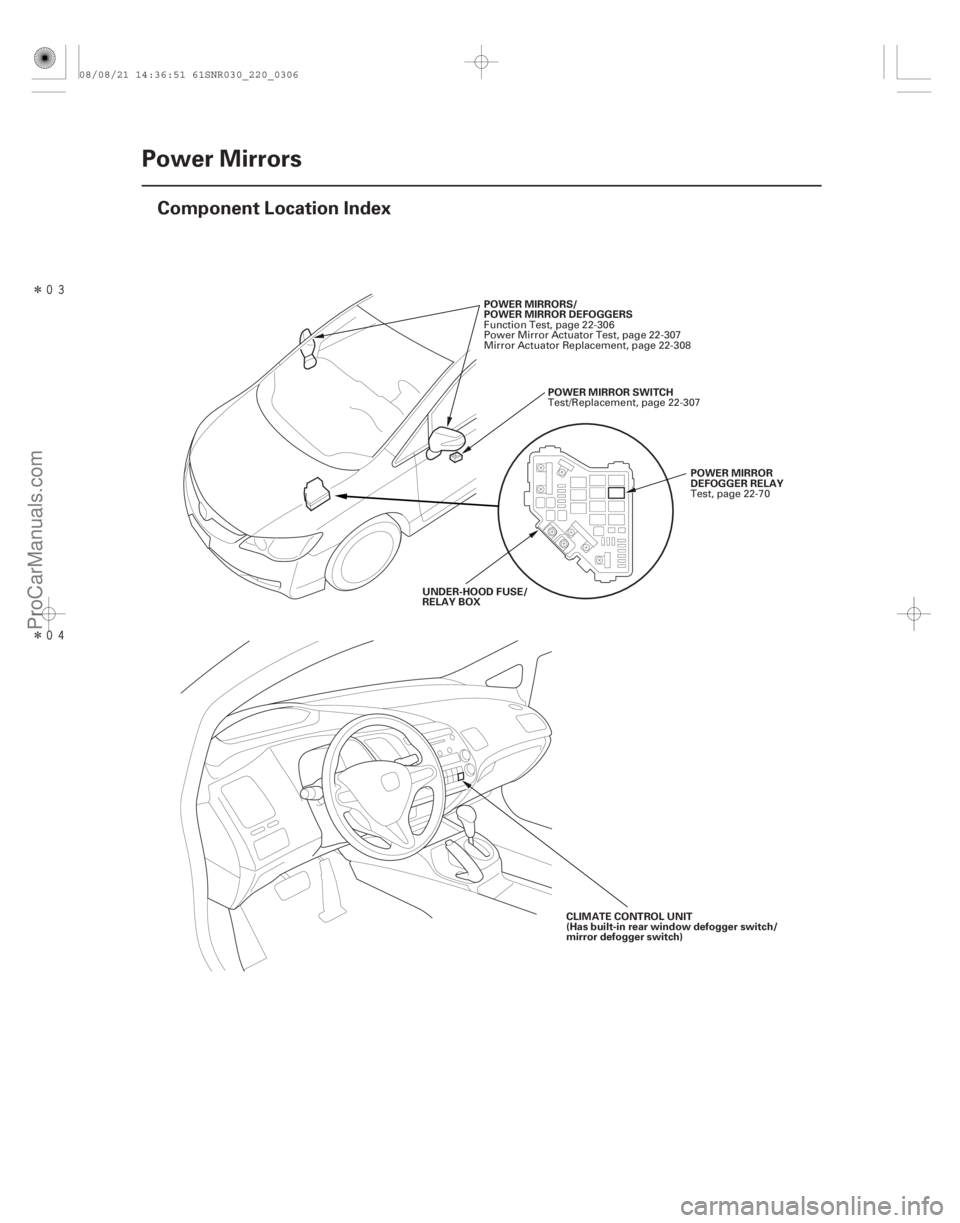
22-304Power Mirrors
Component Location Index
POWER MIRRORS/
POWER MIRROR DEFOGGERS
POWERMIRRORSWITCH
POWER MIRROR
DEFOGGER RELAY
UNDER-HOOD FUSE/
RELAY BOX
CLIMATE CONTROL UNIT
(Has built-in rear window defogger switch/
mirror defogger switch)
Function Test, page 22-306
Power Mirror Actuator Test, page 22-307
Mirror Actuator Replacement, page 22-308
Test/Replacement, page 22-307
Test, page 22-70
08/08/21 14:36:51 61SNR030_220_0306
ProCarManuals.com
DYNOMITE -2009-
Page 2255 of 2893
���
�(�#�'�������������������������������
�������)����
22-305
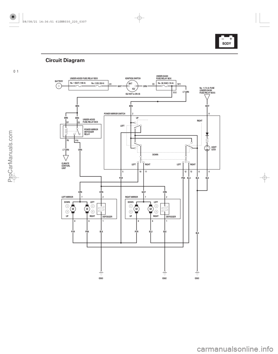
Circuit Diagram
C3 N11
G12
DEFOGGER
DEFOGGER 4
6
ORN
BRN
BRNBRN
G503 G502
PUR
PNK BLK PURBLUBLK1
6
8
1
6
8 2
7
2
7
GRN
ORN ORN
WHT
BLK
G503 BLK
BLK
UP RIGHTLEFT
DOWN
RIGHT MIRROR
LEFT MIRROR POWER MIRROR SWITCH
BRN LT GRN
IG2 HOT in ON (II)
BLU
PNK
LT GRN WHT
DOWN LEFT
RIGHT
UP IGNITION SWITCH
BAT
IG2
UNDER-HOOD FUSE/RELAY BOX
No. 2 (IG) (50 A)
BATTERY
ORN
2
DOWN RIGHT
LEFT UP
RIGHT
LEFT LEFTRIGHT
5
PUR 10 11
12 139
WHT
No. 1 (BAT) (100 A)
UNDER-DASH
FUSE/RELAY BOX
No. 1 (7.5 A) FUSE
(UNDER-DASH
FUSE/RELAY BOX)
CLIMATE
CONTORL
UNIT LIGHT
(LED)
POWER MIRROR
DEFOGGER
RELAY
UNDER-HOOD
FUSE/RELAY BOX H1
D7 E2
F8 F15 No.36(HAC)(10A)
08/08/21 14:36:51 61SNR030_220_0307
ProCarManuals.com
DYNOMITE -2009-
Page 2256 of 2893
����
Both mirrors Left mirror
Right mirror
Defogger
22-306Power Mirrors
Function Test
BLK
WHTGRN
WHTPNK BLU PUR
BRN
BLK
A
B
1. Remove the power win")
����
�(�#�'�������������������������������
�������)����
Both mirrors Left mirror
Right mirror
Defogger
22-306Power Mirrors
Function Test
BLK
WHTGRN
WHTPNK BLU PUR
BRN
BLK
A
B
1. Remove the power window master switch (A).
2. Disconnect the 13P connector (B) from the powermirror switch.
3. Choose the appropriate test based on the symptom:
Both mirrors don’t work, go to step 4.
Leftmirrordoesn’twork,gotostep6.
Right mirror doesn’t work, go to step 7.
4. Measure the voltage between terminal No. 2 and body ground with the ignition switch turned to ON
(II).
There should be battery voltage.
If there is no voltage, check for: – Blown No. 36 (10 A) fuse in the under-dash fuse/relay box.
– AnopenintheBRNwire.
If there is battery voltage, go to step 5.
5. Check for continuity between terminal No. 6 and body ground. There should be continuity.
If there is no continuity, check for: – AnopenintheBLKwire.
– Poor ground (G 503).
If there is continuity, check both mirrors individually as described in the next steps. 6. Connect terminals No. 2 and No. 10, and terminals
No. 5 (or No. 12) and No. 6 with jumper wires.
The left mirror should tilt down (or swing left) with
the ignition switch to ON (II).
If the left mirror does not tilt down (or does not swing left), check for an open in the PUR (or PNK)
wire between the left mirror and the 13P
connector.
If the wire is OK, check the left mirror actuator.
If the mirror neither tilts down nor swings left, repair the GRN wire.
If the mirror works properly, check the mirror switch.
7. Connect terminals No. 2 and No. 11, and terminals No. 5 (or No. 13) and No. 6 with jumper wires. The
right mirror should tilt down (or swing left) with the
ignition switch to ON (II).
If the mirror does not tilt down (or does not swing left), check for an open in the PUR (or BLU) wire
between the right mirror and the 13P connector.
If the wire is OK, check the right mirror actuator.
If the mirror neither tilts down nor swings left, repair the WHT wire.
If the mirror works properly, check the mirror switch.
8. Connect the power mirror defogger relay terminals No. 1 and No. 2 in the under-hood fuse/relay box
with a jumper wire, and measure the voltage
between mirror connectors terminal No. 1 and
body ground. There should be battery voltage and
both mirrors should warm up with the ignition
switch to ON (II). If there is no voltage or neither warms up, check for:
– AnopenintheORNwire.
– Blown No. 36 (10 A) fuse in the under-dash fuse/relay box.
If only one fails to warm up, check: – Its defogger.
– Poor ground (G 503).
If both warm up, check the defogger switch.
Wire side of female terminals
08/08/21 14:36:52 61SNR030_220_0308
ProCarManuals.com
DYNOMITE -2009-
Page 2257 of 2893
���
���
����
�(�#��������������������������������
�������)���� Defogger Test
22-30722-307
Power Mirror Switch Test/
Replacement Power Mirror A")
���
�����(�#�'�������������������������������
�������)���
���
����
�(�#�'�������������������������������
�������)���� Defogger Test
22-30722-307
Power Mirror Switch Test/
Replacement Power Mirror Actuator Test
A
Terminal
Position
UP 26 13
5
DOWN LEFT
RIGHT UP
DOWN
LEFT
RIGHT
L
R 1211
10 A
B
Position Terminal
87 6
TILT UP
TILT DOWN
SWING LEFT
SWING RIGHT
1. Remove the driver’s door grip cover (see page 20-7).
2. Disconnect the 13P connector from the power mirror switch (A), then remove the two screws and
power mirror switch.
3. Check for continuity between the terminals in each switch position according to the table.
4. If the continuity is not as specified, remove the screws and replace the switch.
5. Install the power mirror switch in the reverse order of removal. 1. Remove the door panel (see page 20-7).
2. Disconnect the 8P connector (A) from the power
mirroractuator(B).
3. Check actuator operation by connecting power and ground according to the table.
4. If the mirror fails to work properly, replace the mirror actuator.
5. Check for continuity between terminals No. 1 and No. 2 of the 8P connector. These should be
continuity.
6. If the continuity is not as specified, check for: Anopeninthewire.
A faulty mirror holder.
Wire side of
female terminals
08/08/21 14:36:52 61SNR030_220_0309
ProCarManuals.com
DYNOMITE -2009-
Page 2258 of 2893
���
��������
����
�(�#�'�������������������������������
� �����)����
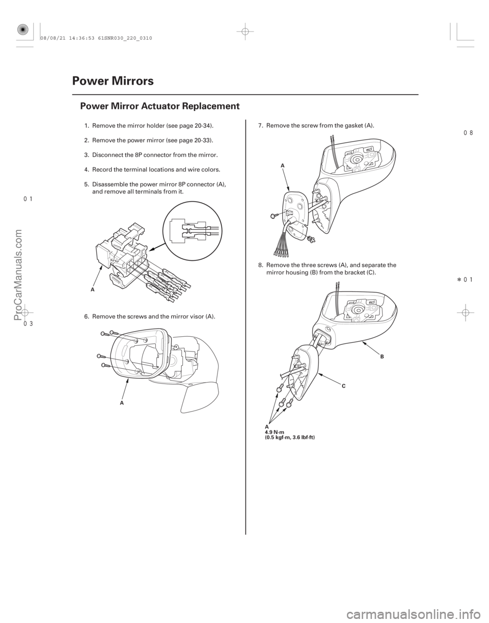
22-308 Power Mirrors
Power Mirror Actuator Replacement
A
A A
CB
A
4.9 N·m
(0.5 kgf·m, 3.6 lbf·ft)
1. Remove the mirror holder (see page 20-34).
2. Remove the power mirror (see page 20-33).
3. Disconnect the 8P connector from the mirror.
4. Record the terminal locations and wire colors.
5. Disassemble the power mirror 8P connector (A), and remove all terminals from it.
6. Remove the screws and the mirror visor (A). 7. Remove the screw from the gasket (A).
8. Remove the three screws (A), and separate the
mirror housing (B) from the bracket (C).
08/08/21 14:36:53 61SNR030_220_0310
ProCarManuals.com
DYNOMITE -2009-