Page 2259 of 2893
����
��������
����
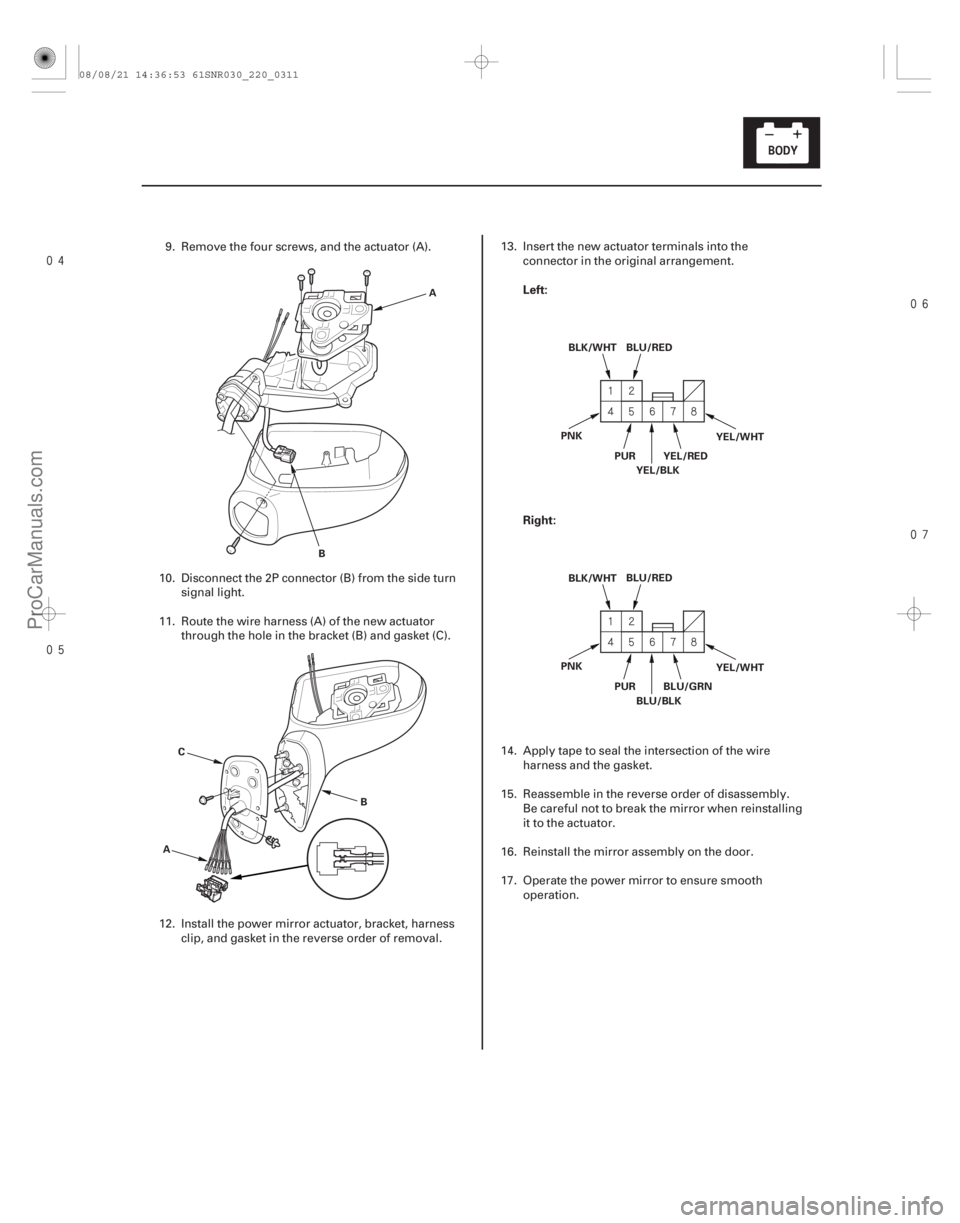
Left:
Right:
22-309
A
B
A B
C BLU/RED
BLK/WHT
YEL/RED
PUR
YEL/BLK YEL/WHT
PNK
BLU/RED
BLK/WHT
BLU/GRN
PUR
BLU/BLK YEL/WHT
PNK
9. Remove the four screws, and the actuator (A).
10. Disconnect the 2P connector (B) from the side turn signal light.
11. Route the wire harness (A) of the new actuator through the hole in the bracket (B) and gasket (C).
12. Install the power mirror actuator, bracket, harness clip, and gasket in the reverse order of removal. 13. Insert the new actuator terminals into the
connector in the original arrangement.
14. Apply tape to seal the intersection of the wire harness and the gasket.
15. Reassemble in the reverse order of disassembly. Be careful not to break the mirror when reinstalling
it to the actuator.
16. Reinstall the mirror assembly on the door.
17. Operate the power mirror to ensure smooth operation.
08/08/21 14:36:53 61SNR030_220_0311
ProCarManuals.com
DYNOMITE -2009-
Page 2260 of 2893
����
�(�#�'���������������
�����
�����������������)����
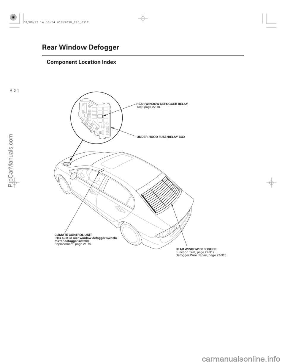
22-310Rear Window Defogger
Component Location Index
REAR WINDOW DEFOGGER RELAY
UNDER-HOOD FUSE/RELAY BOX
REAR WINDOW DEFOGGER
CLIMATE CONTROL UNIT
(Has built-in rear window defogger switch/
mirror defogger switch) Test, page 22-70
Function Test, page 22-312
Defogger Wire Repair, page 22-313
Replacement, page 21-75
08/08/21 14:36:54 61SNR030_220_0312
ProCarManuals.com
DYNOMITE -2009-
Page 2261 of 2893
����
�(�#�'���������������
�����
�����������������)����
22-311
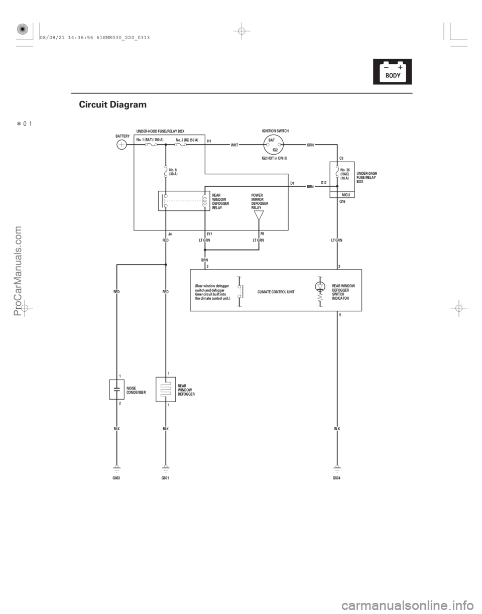
Circuit Diagram
IG2 HOT in ON (II) G12C3
CLIMATE CONTROL UNIT LT GRN
BLK
G603 2 BRN
LT GRN LT GRN
BLK No. 2 (IG) (50 A)
G801
1
RED RED UNDER-HOOD FUSE/RELAY BOX
G504BLK
RED
BRN
No. 8
(30 A)
No. 36
(HAC)
(10 A)
ORN
IGNITION SWITCH
IG2
BAT
WHT
BATTERY
No. 1 (BAT) (100 A)
UNDER-DASH
FUSE/RELAY
BOX
REAR
WINDOW
DEFOGGER
RELAY
REAR WINDOW
DEFOGGER
SWITCH
INDICATOR
(Rear window defogger
switch and defogger
timer circuit built into
the climate control unit.)
NOISE
CONDENSER REAR
WINDOW
DEFOGGER POWER
MIRROR
DEFOGGER
RELAY
H1
D1
J4 F17 F8
2 3
5
1
1 MICU
Q16
08/08/21 14:36:55 61SNR030_220_0313
ProCarManuals.com
DYNOMITE -2009-