Page 1603 of 2893
����
����
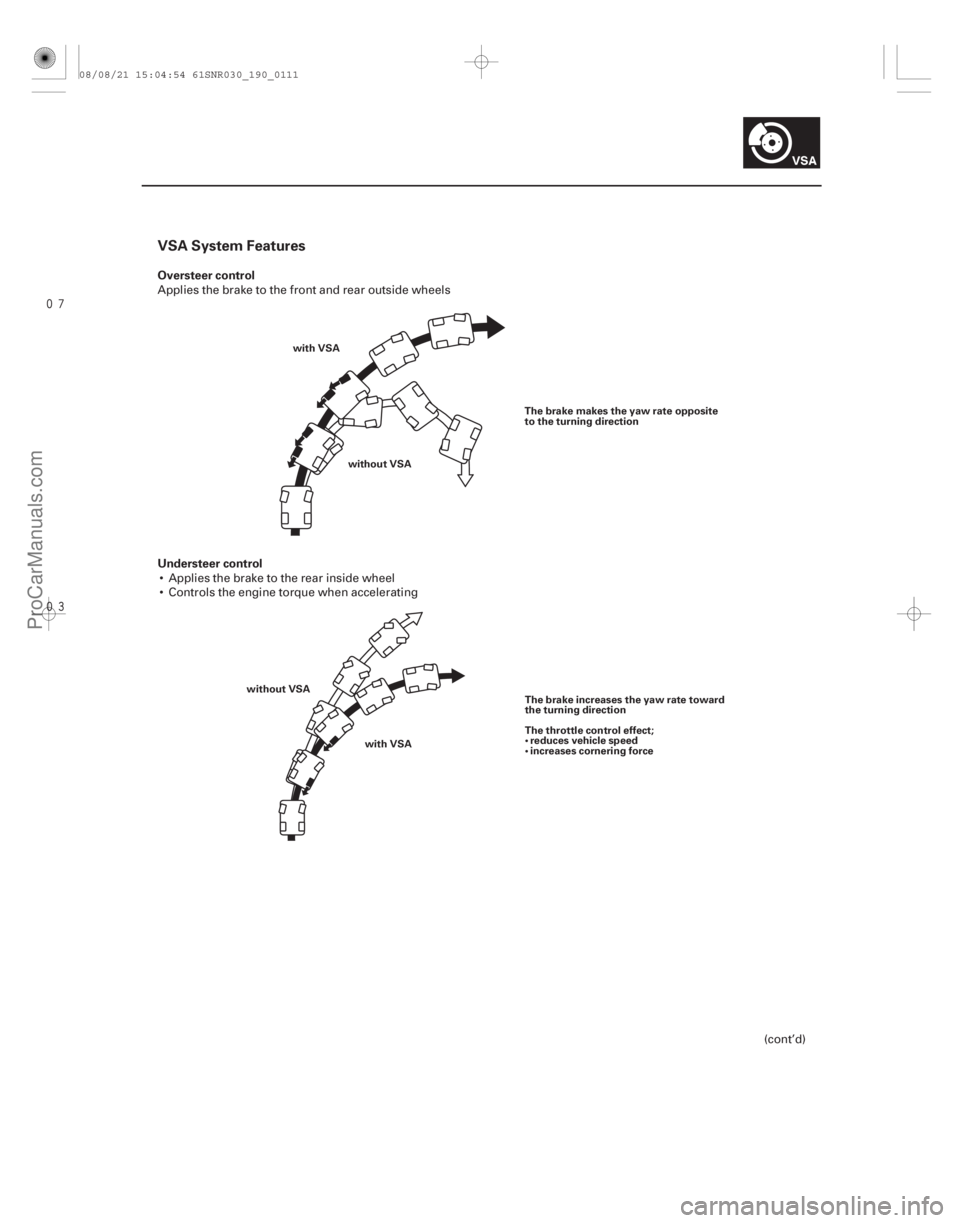
VSA System Features
Oversteer control
Understeer control
19-111
with VSAwithout VSA The brake makes the yaw rate opposite
to the turning direction
with VSA
without VSA
The brake increases the yaw rate toward
the turning direction
The throttle control effect;
reduces vehicle speed
increases cornering force
Applies the brake to the front and rear outside wheels
Applies the brake to the rear inside wheel
Controls the engine torque when accelerating
(cont’d)
08/08/21 15:04:54 61SNR030_190_0111
ProCarManuals.com
DYNOMITE -2009-
Page 1605 of 2893

�
��
Modulator Unit
Mode VSA NOValveVSA NC
Valve Inlet
Solenoid Valve Outlet
Solenoid Valve Brake Fluid
Pressure
intensifying
mode
Pressure
retaining
mode
Pressure
reducing
mode
Pressure
adding
mode
19-113
FL RR RL
FR
OUT OUT
IN
IN
VSA NO VSA NC
REGULATOR
VALVE PRESSURE
SENSOR
DAMPING
CHAMBER
RESERVOIR MOTOR
RESERVOIRVSA NC VSA NO
REGULATOR
VALVE IN
IN OUT
OUT
MODULATOR UNIT
IN : INLET SOLENOID VALVE (NORMALLY OPEN)
OUT : OUTLET SOLENOID VALVE (NORMALLY CLOSED)
MASTER CYLINDER
The modulator unit consists of the inlet solenoid valve, the outlet solenoid valve, the VSA NO (normally open)
solenoid valve, the VSA NC (normally closed) solenoid valve, the reservoir, the pump, the pump motor, and the
damping chamber.
The hydraulic control has three modes at ABS action; pressure intensifying, pressure retaining, and pressure reducing.
Pressure adding mode is combined the TCS, VSA, and brake assist action.
The hydraulic circuit is an independent four channel type; one channel for each wheel.
open closed open closed Master cylinder fluid is pumped out to
the caliper.
open closed closed closed Caliper fluid is retained by the inlet and outlet valves.
open closed closed open Caliper fluid flows through the outlet valve to the reservoir.
The motor pumps the reservoir fluid
through the damping chamber to
the master cylinder .
closed open open closed Master cylinder fluid is pumped out by pump with motor through VSA
NC valve to the caliper.
Caliper fluid pressure exceeds
master cylinder pressure.
: The motor will keep running until the operation of the one anti-lock brake control is finished with the first pressure reducing mode.
08/08/21 15:04:55 61SNR030_190_0113
ProCarManuals.com
DYNOMITE -2009-
Page 1607 of 2893
�����
�´�´
�´
�´ �´
�´
�´
19-115
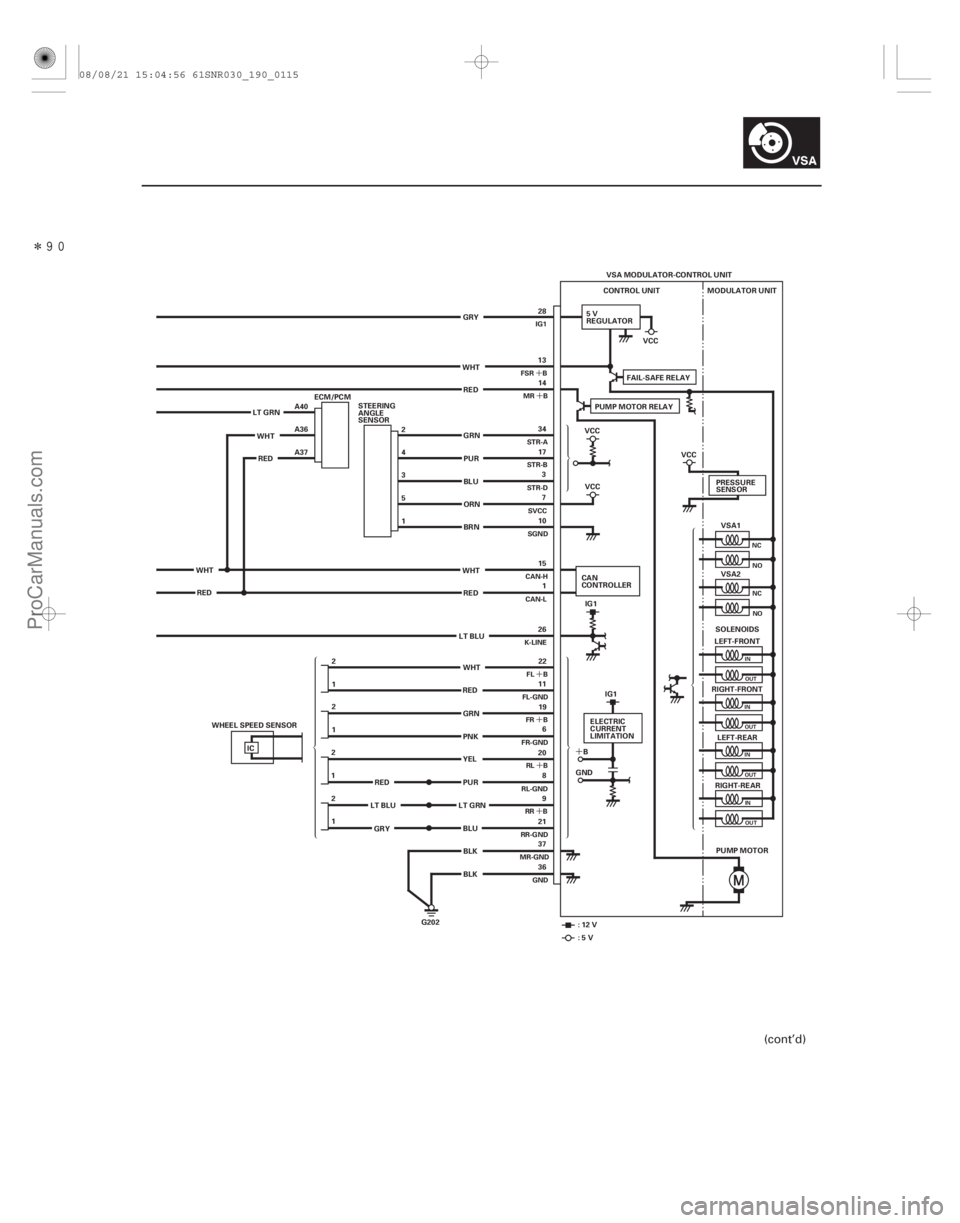
VSA MODULATOR-CONTROL UNIT
CONTROL UNIT
5V
REGULATOR MODULATOR UNIT
VSA1
VSA2
LEFT-FRONT
RIGHT-FRONT LEFT-REAR
RIGHT-REAR
PUMP MOTOR
G202 PRESSURE
SENSOR
SOLENOIDS
IC 13
14
22
11 19 6
20 8
9
21
37
36 34
17 3
7
10
15 1
26
1 2 1
2
2
1
1 2 28
WHT RED
GRN
PUR
BLU
ORN
BRN
WHT RED
LT BLU
GRN
PNK
BLK BLK
LT GRN
WHTRED A40
A36
A37
WHT RED 2
4
3
5
1
STEERING
ANGLE
SENSOR
PUR
LT GRN
RED
LT BLU
GRY PUMP MOTOR RELAY
FAIL-SAFE RELAY
VCC
VCC
IG1
CAN
CONTROLLER
:12V :5V VCC
ELECTRIC
CURRENT
LIMITATION
B
GND IG1
VCC
GRY
BLU YEL
RED
WHT
ECM/PCM
WHEEL SPEED SENSOR
NC NO
NCNO
IN
OUT
IN OUT
IN OUT
INOUT
FSR B MR B
FL B
FL-GND FR B
FR-GND
RL B
RL-GND RR B
RR-GND
MR-GND
GND
STR-A
STR-B
STR-D
SVCC
SGND
CAN-H
CAN-L
K-LINE IG1
(cont’d)
08/08/21 15:04:56 61SNR030_190_0115
ProCarManuals.com
DYNOMITE -2009-
Page 1608 of 2893
���
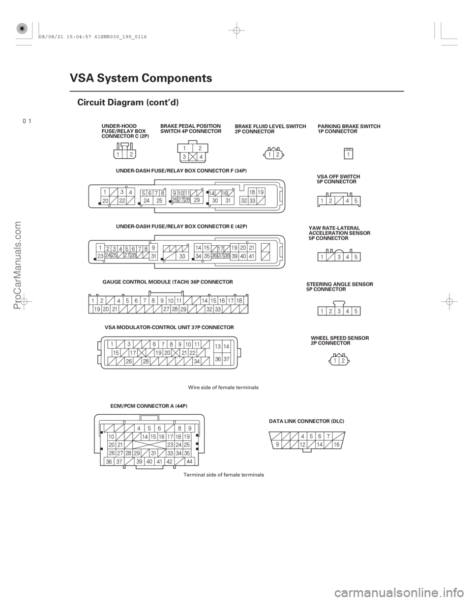
19-116VSA System Components
Circuit Diagram (cont’d)
BRAKE PEDAL POSITION
SWITCH 4P CONNECTOR
PARKING BRAKE SWITCH
1P CONNECTOR
DATA LINK CONNECTOR (DLC) VSA OFF SWITCH
5P CONNECTOR
YAW RATE-LATERAL
ACCELERATION SENSOR
5P CONNECTOR
STEERING ANGLE SENSOR
5P CONNECTOR
BRAKE FLUID LEVEL SWITCH
2P CONNECTOR
UNDER-HOOD
FUSE/RELAY BOX
CONNECTOR C (2P)
WHEEL SPEED SENSOR
2P CONNECTOR
ECM/PCM CONNECTOR A (44P)
GAUGE CONTROL MODULE (TACH) 36P CONNECTOR
VSA MODULATOR-CONTROL UNIT 37P CONNECTOR UNDER-DASH FUSE/RELAY BOX CONNECTOR F (34P)
UNDER-DASH FUSE/RELAY BOX CONNECTOR E (42P)
Wire side of female terminals
Terminal side of female terminals
08/08/21 15:04:57 61SNR030_190_0116
ProCarManuals.com
DYNOMITE -2009-
Page 1609 of 2893
����
�´ �´
�´ �´
�µ
�µ �µ
�µ
DTC 11-13:
DTC 13-13:
DTC 15-13:
DTC 17-13:
YES
NO DTC VSA Modulator-control Unit 37P
Connector Terminal
YES")
�´
���
�(�#�'��������� �����
�������'�
�
�
���������)����
�´ �´
�´ �´
�µ
�µ �µ
�µ
DTC 11-13:
DTC 13-13:
DTC 15-13:
DTC 17-13:
YES
NO DTC VSA Modulator-control Unit 37P
Connector Terminal
YES
NO
19-117
DTC Troubleshooting
VSA MODULATOR-CONTROL UNIT 37P CONNECTOR FR B (GRN)RL-GND (PUR)
FR-GND (PNK) RR B (LT GRN)
RL B (YEL) FL B (WHT)
RR-GND (BLU) FL-GND (RED)
Right-front Wheel Speed Sensor
Circuit Malfunction
Left-front Wheel Speed Sensor
Circuit Malfunction
Right-rear Wheel Speed Sensor
Circuit Malfunction
Left-rear Wheel Speed Sensor
Circuit Malfunction
1. Turn the ignition switch to ON (II).
2. Clear the DTC with the HDS.
3. Turn the ignition switch to LOCK (0), then turn it to
ON (II) again.
4. Check for DTCs with the HDS.
Go to step 5.
Intermittent failure, the system is OK at this
time. Check for loose terminals between the wheel
speed sensor 2P connector and the VSA modulator-
control unit 37P connector. Refer to intermittent
failures troubleshooting (see page 19-98).
5. Turn the ignition switch to LOCK (0).
6. Disconnect the VSA modulator-control unit 37P connector (see step 2 on page 19- 171).
7. Disconnect the appropriate wheel speed sensor 2P connector. 8. Check for continuity between the appropriate VSA
modulator-control unit 37P connector wheel speed
sensor B and GND terminals (see table).
11-13 No. 19 No. 6
13-13 No. 22 No. 11
15-13 No. 9 No. 21
17-13 No. 20 No. 8
Repair short in the wires between the
appropriate wheel speed sensor and the VSA
modulator-control unit.
Go to step 9.
(cont’d)
Wire side of female terminals
I s DT C 11-13, 13-13, 15 -13, and / or 17 -13indicated?
Is there continuity?
08/08/21 15:04:57 61SNR030_190_0117
ProCarManuals.com
DYNOMITE -2009-
Page 1610 of 2893

����
�����
�´
�´
�´
�´ �´
�´
�´
�´
�µ
�µ �µ
�µ
DTC
YES
NO DTC
YES
NO
VSA Modulator- control Unit 37P
Connector Terminal Appropriate Wheel
Speed Sensor 2P
Connector Terminal VSA Modulator-
control Unit 37P
Connector Terminal Appropriate Wheel
Speed Sensor 2P
Connector Terminal
19-118 VSA System Components
DTC Troubleshooting (cont’d)
RR B (LT GRN)
FL B (WHT)
FR B (GRN)
RL B (YEL) RR B
(LT BLU)
FL B
(WHT)
FR B
(GRN)
RL B
(YEL)
LEFT-
REAR
RIGHT-
FRONT RIGHT-
REARLEFT-
FRONT
WHEEL SPEED SENSOR 2P CONNECTOR
VSA MODULATOR-CONTROL UNIT 37P CONNECTOR FL-GND
(RED)
RR-GND
(GRY)
RL-GND
(RED)
FR-GND
(PNK) RIGHT-
FRONT
LEFT-
REAR LEFT-
FRONTRIGHT-
REAR
WHEEL SPEED SENSOR 2P CONNECTOR
VSA MODULATOR-CONTROL UNIT 37P CONNECTOR FL-GND (RED)
RR-GND (BLU)
RL-GND (PUR)
FR-GND (PNK)
9. Check for continuity between the appropriate VSA modulator-control unit 37P connector terminal and
the wheel speed sensor 2P connector terminal (see
table).
11-13 No. 9 Right-front
13-13 No. 22 Left-front
15-13 No. 9 Right-rear
17-13 No. 20 Left-rear
Go to step 10.
Repair open in the wire between the
appropriate wheel speed sensor and the VSA
modulator-control unit. 10. Check for continuity between the appropriate VSA
modulator-control unit 37P connector terminal and
the wheel speed sensor 2P connector terminal (see
table).
11-13 No. 6 Right-front
13-13 No. 11 Left-front
15-13 No. 21 Right-rear
17-13 No. 8 Left-rear
Go to step 11.
Repair open in the wire between the
appropriate wheel speed sensor and the VSA
modulator-control unit.
Wire side of female terminals
Terminal side of female terminals
Wire side of female terminals
Terminal side of female terminals
Is there continuity?
Is there continuity?
08/08/21 15:04:58 61SNR030_190_0118
ProCarManuals.com
DYNOMITE -2009-
Page 1611 of 2893
 RL-GN")
��������
�´�´
�´
�´
�´�´
�´
�´
�µ
�µ �µ
�µ
DTC VSA Modulator-control Unit 37P
Connector Terminal
YES
NO DTC VSA Modulator-control Unit 37P
Connector Terminal
YES
NO
19-119
FR B (GRN) RL-GND (PUR)
FR-GND (PNK) RR B (LT GRN)
FL-GND (RED)
FL B (WHT)
RR-GND
(BLU)
RL B (YEL)
VSA MODULATOR-CONTROL UNIT 37P CONNECTOR
FR B (GRN)RL-GND (PUR)
FR-GND (PNK) RR B (LT GRN)
FL-GND (RED)
FL B (WHT)
RR-GND
(BLU)
RL B (YEL)
VSA MODULATOR-CONTROL UNIT 37P CONNECTOR
11. Check for continuity between body ground and the
appropriate VSA modulator-control unit 37P
connector terminals (see table).
11-13 No. 19 No. 6
13-13 No. 22 No. 11
15-13 No. 9 No. 21
17-13 No. 20 No. 8
Repair short to body ground in the wire
between the appropriate wheel speed sensor and
the VSA modulator-control unit.
Go to step 12. 12. Turn the ignition switch to ON (II).
13. Measure the voltage between body ground and the
appropriate VSA modulator-control unit 37P
connector terminals (see table).
11-13 No. 19 No. 6
13-13 No. 22 No. 11
15-13 No. 9 No. 21
17-13 No. 20 No. 8
Repair short to power in the wire between
the appropriate wheel speed sensor and the VSA
modulator-control unit.
Go to step 14.
(cont’d)
Wire side of female terminals Wire side of female terminals
Is there continuity?Is t her e 0.1 V or mor e?
08/08/21 15:04:58 61SNR030_190_0119
ProCarManuals.com
DYNOMITE -2009-
Page 1612 of 2893
����
�µ
�µ �µ
�µ
YES
NO
YES
NO
DTC 12-11:
DTC 14-11:
DTC 16-11:
DTC 18-11:
19-12019-120VSA System Components
DTC Troubleshooting (cont’d)
14. Turn t")
�(�#�'��������� �����
�������'�
���
�
�������)����
�µ
�µ �µ
�µ
YES
NO
YES
NO
DTC 12-11:
DTC 14-11:
DTC 16-11:
DTC 18-11:
19-12019-120VSA System Components
DTC Troubleshooting (cont’d)
14. Turn the ignition switch to LOCK (0).
15. Substitute the appropriate wheel speed sensor with
opposite wheel speed sensor, or with a known-
good wheel speed sensor.
16. Reconnect all connectors.
17. Turn the ignition switch to ON (II).
18. Clear the DTC with the HDS.
19. Turn the ignition switch to LOCK (0), then turn it to ON (II) again.
20. Check for DTCs with the HDS.
Check for loose terminals in the VSA
modulator-control unit 37P connector. If necessary,
substitute a known-good VSA modulator-control
unit (see page 19-171), and retest.
Replace the original wheel speed sensor
(see page 19-173). NOTE: These DTCs may be caused by electrical
interference. Check for aftermarket devices installed in
the vehicle when these DTCs are indicated.
1. Turn the ignition switch to ON (II).
2. Clear the DTC with the HDS.
3. Test-drive the vehicle. NOTE: Drive the vehicle on the road, not on a lift.
4. Check for DTCs with the HDS.
If DTC 12-12, 14-12, 16-12, or 18-12 is
indicated at the same time, do the DTC 12-12,
14-12, 16-12, or 18-12 troubleshooting first
(see page 19-121). If DTC 12-12, 14-12, 16-12, or
18-12 is not indicated, go to step 5.
If any other DTCs are indicated, go to the
indicated DTCs troubleshooting. If DTCs are not
indicated, there is an intermittent failure, the
system is OK at this time. Check for loose terminals
between the wheel speed sensor 2P connector and
the VSA modulator-control unit 37P connector.
Refer to intermittent failures troubleshooting
(see page 19-98).Right-front Wheel Speed Sensor
Electrical Noise or Intermittent Interruption
Left-front Wheel Speed Sensor
Electrical Noise or Intermittent Interruption
Right-rear Wheel Speed Sensor
Electrical Noise or Intermittent Interruption
Left-rear Wheel Speed Sensor
Electrical Noise or Intermittent Interruption
I s DT C i nd i cat ed t hat i s i nd i cat ed i n st ep 4?
I s DT C 12 -11, 14-11, 16-11, and / or 18-11indicated?
08/08/21 15:04:58 61SNR030_190_0120
ProCarManuals.com
DYNOMITE -2009-