Page 1565 of 2893
�����(�#���������� �����
����������
�
�
�������)����
�µ
�µ
�µ
�µ �µ
�µ
DTC 12-23:
DTC 14-23:
DTC 16-23:
DTC 18-23: DTC 21-11:
DTC 22-11:
DTC 23-11")
�(�#�'��������� �����
�������'�
�������������)�����(�#�'��������� �����
�������'���
�
�
�������)����
�µ
�µ
�µ
�µ �µ
�µ
DTC 12-23:
DTC 14-23:
DTC 16-23:
DTC 18-23: DTC 21-11:
DTC 22-11:
DTC 23-11:
DTC 24-11:
YES
NO
DTC Appropriate Wheel Speed Sensor
YES
NO YES
NO
19-7219-72ABS Components
DTC Troubleshooting (cont’d)
Right-front Wheel Speed Sensor
InstallationError(0to15km/h(0to9mph))
Left-front Wheel Speed Sensor
InstallationError(0to15km/h(0to9mph))
Right-rear Wheel Speed Sensor
InstallationError(0to15km/h(0to9mph))
Left-rear Wheel Speed Sensor
InstallationError(0to15km/h(0to9mph)) Right-front Magnetic Encoder
(Wheel Bearing) Malfunction (Pulse Missing)
Left-front Magnetic Encoder
(Wheel Bearing) Malfunction (Pulse Missing)
Right-rear Magnetic Encoder
(Wheel Bearing) Malfunction (Pulse Missing)
Left-rear Magnetic Encoder
(Wheel Bearing) Malfunction (Pulse Missing)
1. Test-drive the vehicle between 1 km/h (1 mph) and
15 km/h (9 mph).
NOTE: Drive the vehicle on the road, not on a lift.
2. Check the RF, LF, RR, LR WHEEL SPEED in the ABS DATA LIST with the HDS.
Intermittent failure, the system is OK at this
time. Check for loose terminals between the wheel
speed sensor 2P connector and the ABS modulator-
control unit 25P connector. Refer to intermittent
failures troubleshooting (see page 19-50).
Go to step 3.
3. Turn the ignition switch to LOCK (0).
4. Check that the appropriate wheel speed sensor is properly mounted (see page 19-92).
12-23 Right-front
14-23 Left-front
16-23 Right-rear
18-23 Left-rear
Replace the appropriate wheel speed sensor
(see page 19-92).
Reinstall the wheel speed sensor, and check
the mounting position (see page 19-92). 1. Turn the ignition switch to ON (II).
2. Clear the DTC with the HDS.
3. Test-drive the vehicle at 20 km/h (13 mph) or more,
and go a distance of 100 m (328 ft) or more.
NOTE: Drive the vehicle on the road, not on a lift.
4. Check for DTCs with the HDS.
Go to step 5.
Intermittent failure, the system is OK at this
time. Check for loose terminals between the wheel
speed sensor 2P connector and the ABS modulator-
control unit 25P connector. Refer to intermittent
failures troubleshooting (see page 19-50).
5. Turn the ignition switch to LOCK (0).
Are all f our values the same?
Is t he w heel speed sensor i nst al l at i on OK ? I s DT C 2 1-11, 2 2 -11, 2 3-11, and / or 2 4-11
indicated?
08/08/21 15:03:14 61SNR030_190_0072
ProCarManuals.com
DYNOMITE -2009-
Page 1566 of 2893
����
�µ
�µ
DTC Appropriate MagneticEncoder Note
YES
NO Subcode Malfunction Note (DTC)
DTC 31-xx :
DTC 32-xx :
DTC 33-xx :
DTC 34-xx :
DTC 35-xx :
DTC 36")
�(�#�'��������� �����
�������'���
�-�-�������)����
�µ
�µ
DTC Appropriate MagneticEncoder Note
YES
NO Subcode Malfunction Note (DTC)
DTC 31-xx :
DTC 32-xx :
DTC 33-xx :
DTC 34-xx :
DTC 35-xx :
DTC 36-xx :
DTC 37-xx :
DTC 38-xx :
19-7319-73
6. Inspect the appropriate magnetic encoder for damage, debris, and correct installation.
21-11 Right-front Remove the driveshaft outboard
joint from the
appropriate wheel
hub (see page 18-15).
22-11 Left-front
23-11 Right-rear Remove the hub
bearing unit
(see page 18-32).
24-11 Left-rear
Remove the debris from the magnetic
encoder, or replace the wheel bearing (front) or the
hub bearing unit (rear):
Front: Replace the front wheel bearing (see page 18-18).
Rear: Replace the rear hub bearing unit (see page 18-32).
Clean off debris from the appropriate
magnetic encoder surface on the wheel bearing or
the hub bearing unit, then go to step 1, and
recheck. If the DTC is still present, replace the
appropriate wheel bearing or hub bearing unit. :Any two-character subcode (see table)
01 Solenoid Initial Pulse 31-01, 32-01, 33-01,
34-01, 35-01, 36-01,
37-01, 38-01
21 Solenoid Pulse 31-21, 32-21, 33-21, 34-21, 35-21, 36-21,
37-21, 38-21
22 Solenoid Speculative 31-22, 32-22, 33-22,
34-22, 35-22, 36-22,
37-22, 38-22
23 Solenoid Stuck ON 31-23, 32-23, 33-23,
34-23, 35-23, 36-23,
37-23, 38-23
1. Turn the ignition switch to ON (II).
2. Clear the DTC with the HDS.
3. Turn the ignition switch to LOCK (0), then turn it to ON (II) again.
(cont’d)ABS Right-front Inlet Solenoid
Valve Malfunction
ABS Right-front Outlet Solenoid
Valve Malfunction
ABS Left-front Inlet Solenoid
Valve Malfunction
ABS Left-front Outlet Solenoid
Valve Malfunction
ABS Right-rear Inlet Solenoid
Valve Malfunction
ABS Right-rear Outlet Solenoid
Valve Malfunction
ABS Left-rear Inlet Solenoid
Valve Malfunction
ABS Left-rear Outlet Solenoid
Valve Malfunction
I s t he magnet i c encod er sur f ace OK ?
08/08/21 15:03:14 61SNR030_190_0073
ProCarManuals.com
DYNOMITE -2009-
Page 1567 of 2893
����
�µ
�µ
�µ
�µ
�µ
�µ
YES
NO
DTC Appropriate Wheel
YES
NO
YES
NO
DTC 41-21:
DTC 42-21:
DTC 43-21:
DTC 44-21:
19-7419-74 ABS Components
DTC Troubles")
�(�#�'��������� �����
�������'���
���
�������)����
�µ
�µ
�µ
�µ
�µ
�µ
YES
NO
DTC Appropriate Wheel
YES
NO
YES
NO
DTC 41-21:
DTC 42-21:
DTC 43-21:
DTC 44-21:
19-7419-74 ABS Components
DTC Troubleshooting (cont’d)
4. Check for DTCs with the HDS.
Replace the ABS modulator-control unit
(see page 19-90).
Intermittent failure, the system is OK at this
time. The DTCs may be indicated under these conditions:
The vehicle goes into a spin.
The ABS continues to operate for a long time.
Snow, dirt, or debris build-up on the wheel speed sensor or magnetic encoder.
Misadjusted brake pedal position switch.
Contaminated brake fluid.
1. Raise the vehicle, and support it with safety stands in the proper locations (see page 1-11).
2. Turn the appropriate wheel by hand.
41-21 Right-front
42-21 Left-front
43-21 Right-rear
44-21 Left-rear
Repair the brake drag.
Go to step 3.
3. Check that the appropriate wheel speed sensor is properly mounted (see page 19-92).
Go to step 4.
Reinstall the wheel speed sensor, and check
the mounting position (see page 19-92).Right-front Wheel Lock
Left-front Wheel Lock
Right-rear Wheel Lock
Left-rear Wheel Lock
Is DT C 31-xx, 32-xx, 33-xx, 34-xx, 35-xx, 36-xx, 37 -x x , or 38-x x i nd i cat ed ?
Is there brake drag?Is t he w heel speed sensor i nst al l at i on OK ?
08/08/21 15:03:15 61SNR030_190_0074
ProCarManuals.com
DYNOMITE -2009-
Page 1568 of 2893
����
�µ
�µ �µ
�µ
YES
NO
YES
NO
DTC 51-11:
DTC 51-13:
19-7519-75
4. Turn the ignition switch to ON (II).
5. Clear the DTC with the HDS.
6. Test-drive t")
�(�#�'��������� �����
�������'���
�
�
�������)����
�µ
�µ �µ
�µ
YES
NO
YES
NO
DTC 51-11:
DTC 51-13:
19-7519-75
4. Turn the ignition switch to ON (II).
5. Clear the DTC with the HDS.
6. Test-drive the vehicle at 10 km/h (7 mph) for20 seconds or more.
NOTE: Drive the vehicle on the road, not on a lift.
7. Check for DTCs with the HDS.
Check for loose terminals between the wheel
speed sensor 2P connector and the ABS modulator-
control unit 25P connector. If necessary, substitute
a known-good ABS modulator-control unit
(see page 19-90), and retest.
If any other DTCs are indicated, go to the
indicated DTCs troubleshooting. If DTCs are not
indicated, intermittent failure, the system is OK at
the time. 1. Turn the ignition switch to ON (II).
2. Clear the DTC with the HDS.
3. Turn the ignition switch to LOCK (0), then turn it to
ON (II) again.
4. Wait 5 seconds.
5. Operate any one of the four solenoids, as listed, in the ABS FUNCTION TEST five times with the HDS.
-LFT FT SOLENOID
-RT FT SOLENOID
-LFT REAR SOLENOID
-RT REAR SOLENOID
6. Check for DTCs with the HDS.
Replace the ABS modulator-control unit
(see page 19-90).
Intermittent failure, the system is OK at this
time.Motor Lock
Motor Drive Circuit Malfunction
Is DT C 41-21, 42-21, 43-21, or 44-21 indicated?
I s DT C 5 1-11 or 5 1-13 i nd i cat ed ?
08/08/21 15:03:15 61SNR030_190_0075
ProCarManuals.com
DYNOMITE -2009-
Page 1585 of 2893
���
�(�#�'�����������
�������������������
� �����)�
�� Special Tools Required
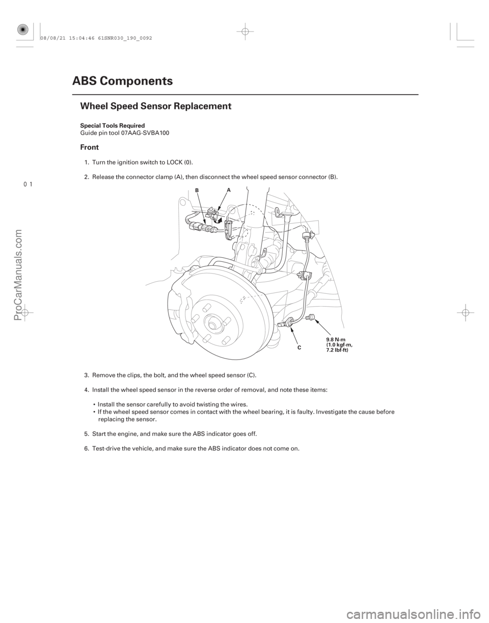
Front
19-92ABS Components
Wheel Speed Sensor Replacement
A
B
C9.8 N·m
(1.0 kgf·m,
7.2 lbf·ft)
Guide pin tool 07AAG-SVBA100
1. Turn the ignition switch to LOCK (0).
2. Release the connector clamp (A), then disconnect the wheel speed sensor connector (B).
3. Remove the clips, the bolt, and the wheel speed sensor (C).
4. Install the wheel speed sensor in the reverse order of removal, and note these items: Install the sensor carefully to avoid twisting the wires.
If the wheel speed sensor comes in contact with the wheel bearing, it is faulty. Investigate the cause beforereplacing the sensor.
5. Start the engine, and make sure the ABS indicator goes off.
6. Test-drive the vehicle, and make sure the ABS indicator does not come on.
08/08/21 15:04:46 61SNR030_190_0092
ProCarManuals.com
DYNOMITE -2009-
Page 1586 of 2893
����
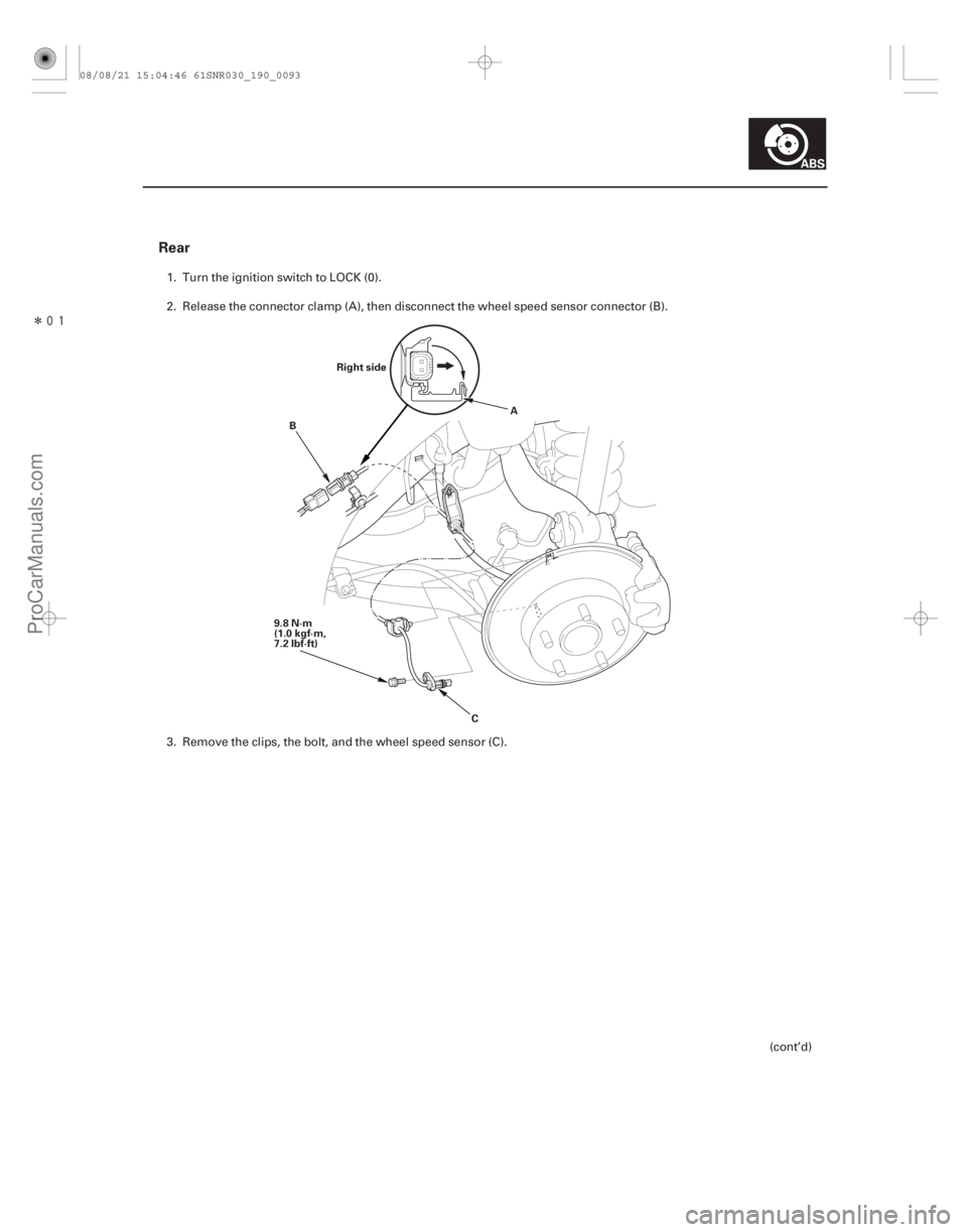
Rear
19-93
Right side
9.8 N·m
(1.0 kgf·m,
7.2 lbf·ft) A
B
C
1. Turn the ignition switch to LOCK (0).
2. Release the connector clamp (A), then disconnect the wheel speed sensor connector (B).
3. Remove the clips, the bolt, and the wheel speed sensor (C). (cont’d)
08/08/21 15:04:46 61SNR030_190_0093
ProCarManuals.com
DYNOMITE -2009-
Page 1587 of 2893

B
A
A
07AAG-SVBA100 B
07AAG-SVBA100
A
4. Apply multi-purpose grease to the wheel speedsensor O-ring (A) and the sen")
�����
����������
19-94ABS Components
Wheel Speed Sensor Replacement (cont’d)
B
A
A
07AAG-SVBA100 B
07AAG-SVBA100
A
4. Apply multi-purpose grease to the wheel speedsensor O-ring (A) and the sensor hole in the knuckle
(B).
5. Insert the guide pin tool (A) into the wheel speed sensor bolt hole until the shoulder of the tool
contacts the wheel speed sensor bracket.
NOTE: To prevent O-ring damage, the wheel speed
sensor must be installed with the guide pin tool. 6. Insert the wheel speed sensor (A) and the guide pin
tool (B) into the bolt hole on the knuckle.
NOTE: To ensure proper alignment when pushing
the wheel speed sensor into the knuckle housing,
do not hold the sensor bracket during installation,
hold the sensor wire.
7. Gently push and pull the wheel speed sensor in and out to make sure the O-ring is sliding properly in its
housing. While you are doing this, make sure the
sensor doesn’t come out of the knuckle assembly. If
the sliding effort is too high, remove the wheel
speed sensor, inspect the O-ring for damage, and
start the installation process again.
8. Remove the guide pin tool, then install the bolt, and tighten it to specified torque.
9. Clean the mating surfaces between the brake disc and the inside of the wheel, then install the front
wheel.
10. Start the engine, and make sure the ABS indicators go off.
11. Test-drive the vehicle, and make sure the ABS indicators do not come on.
08/08/21 15:04:46 61SNR030_190_0094
ProCarManuals.com
DYNOMITE -2009-
Page 1588 of 2893
����
�(�#�'���������������
�����������������������)����
19-96VSA System Components
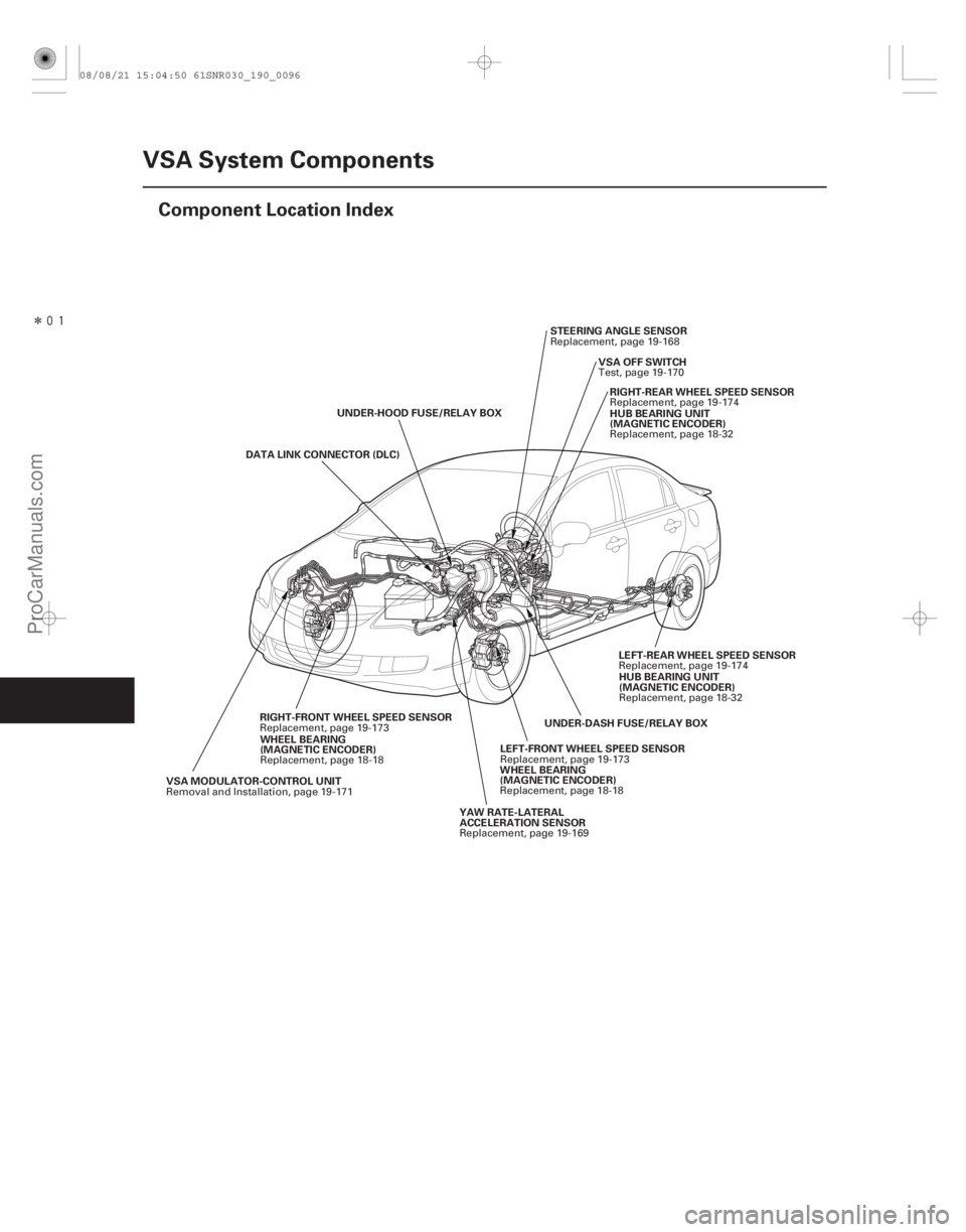
Component Location Index
DATA LINK CONNECTOR (DLC)
UNDER-HOOD FUSE/RELAY BOX
VSA MODULATOR-CONTROL UNIT UNDER-DASH FUSE/RELAY BOX
LEFT-FRONT WHEEL SPEED SENSOR STEERING ANGLE SENSOR
VSA OFF SWITCHRIGHT-REAR WHEEL SPEED SENSOR
YAW RATE-LATERAL
ACCELERATION SENSOR WHEEL BEARING
(MAGNETIC ENCODER) HUB BEARING UNIT
(MAGNETIC ENCODER)
RIGHT-FRONT WHEEL SPEED SENSOR WHEEL BEARING
(MAGNETIC ENCODER) LEFT-REAR WHEEL SPEED SENSOR
HUB BEARING UNIT
(MAGNETIC ENCODER)
Removal and Installation, page 19-171 Replacement, page 19-173Replacement, page 19-168
Test, page 19-170Replacement, page 19-174
Replacement, page 19-169 Replacement, page 18-18 Replacement, page 18-32
Replacement, page 19-173 Replacement, page 18-18 Replacement, page 19-174
Replacement, page 18-32
08/08/21 15:04:50 61SNR030_190_0096
ProCarManuals.com
DYNOMITE -2009-