Page 1546 of 2893
 ON ON (see page 19-73)
-21 ABS Left-front Outlet Sole")
DTCDetection Item ABS Indicator Brake System
Indicator Note
19-53
34 -01 ABS Left-front Outlet Solenoid Valve Malfunction
(Solenoid Initial Pulse) ON ON (see page 19-73)
-21 ABS Left-front Outlet Solenoid Valve Malfunction (Solenoid Pulse) ON ON (see page 19-73)
-22 ABS Left-front Outlet Solenoid Valve Malfunction (Solenoid Speculative) ON ON (see page 19-73)
-23 ABS Left-front Outlet Solenoid Valve Malfunction (Solenoid Stuck ON) ON ON (see page 19-73)
35 -01 ABS Right-rear Inlet Solenoid Valve Malfunction (Solenoid Initial Pulse) ON ON (see page 19-73)
-21 ABS Right-rear Inlet Solenoid Valve Malfunction (Solenoid Pulse) ON ON (see page 19-73)
-22 ABS Right-rear Inlet Solenoid Valve Malfunction (Solenoid Speculative) ON ON (see page 19-73)
-23 ABS Right-rear Inlet Solenoid Valve Malfunction (Solenoid Stuck ON) ON ON (see page 19-73)
36 -01 ABS Right-rear Outlet Solenoid Valve Malfunction (Solenoid Initial Pulse) ON ON (see page 19-73)
-21 ABS Right-rear Outlet Solenoid Valve Malfunction (Solenoid Pulse) ON ON (see page 19-73)
-22 ABS Right-rear Outlet Solenoid Valve Malfunction (Solenoid Speculative) ON ON (see page 19-73)
-23 ABS Right-rear Outlet Solenoid Valve Malfunction (Solenoid Stuck ON) ON ON (see page 19-73)
37 -01 ABS Left-rear Inlet Solenoid Valve Malfunction (Solenoid Initial Pulse) ON ON (see page 19-73)
-21 ABS Left-rear Inlet Solenoid Valve Malfunction (Solenoid Pulse) ON ON (see page 19-73)
-22 ABS Left-rear Inlet Solenoid Valve Malfunction (Solenoid Speculative) ON ON (see page 19-73)
-23 ABS Left-rear Inlet Solenoid Valve Malfunction (Solenoid Stuck ON) ON ON (see page 19-73)
38 -01 ABS Left-rear Outlet Solenoid Valve Malfunction (Solenoid Initial Pulse) ON ON (see page 19-73)
-21 ABS Left-rear Outlet Solenoid Valve Malfunction (Solenoid Pulse) ON ON (see page 19-73)
-22 ABS Left-rear Outlet Solenoid Valve Malfunction (Solenoid Speculative) ON ON (see page 19-73)
-23 ABS Left-rear Outlet Solenoid Valve Malfunction (Solenoid Stuck ON) ON ON (see page 19-73)
41 -21 Right-front Wheel Lock ON ON/OFF (see page 19-74)
42 -21 Left-front Wheel Lock ON ON/OFF (see page 19-74)
43 -21 Right-rear Wheel Lock ON ON/OFF (see page 19-74)
44 -21 Left-rear Wheel Lock ON ON/OFF (see page 19-74)
51 -11 Motor Lock ON OFF (see page 19-75) -12 Motor Drive Circuit Malfunction ON OFF (see page 19-76)
-13 Motor Drive Circuit Malfunction ON OFF (see page 19-75)
52 -12 Motor Stuck OFF ON OFF (see page 19-78)
53 -01 Motor Relay Stuck ON 1 ON OFF (see page 19-78) -12 Motor Relay Stuck ON 2 ON OFF (see page 19-78)
54 -03 Fail-safe Relay 1 Stuck ON ON ON (see page 19-79) -04 Fail-safe Relay 1 Stuck OFF (Initial) ON ON (see page 19-80)
-21 Fail-safe Relay 1 Stuck OFF (Main) ON ON (see page 19-80)
61 -01 ABS Modulator-control Unit Initial IG Low Voltage ON ON (see page 19-81) -21 ABS Modulator-control Unit Power Source Low Voltage 1 ON ON (see page 19-81)
-22 ABS Modulator-control Unit Power Source Low Voltage 2 ON OFF (see page 19-81)
-23 ABS Modulator-control Unit Power Source Low Voltage 3 ON ON (see page 19-81)
62 -21 ABS Modulator-control Unit IG High Voltage ON ON (see page 19-82)
: Brake system indicator turns ON when two or more wheels fail.
(cont’d)
08/08/21 15:02:16 61SNR030_190_0053
ProCarManuals.com
DYNOMITE -2009-
Page 1549 of 2893
�•�•�•
�´
�´ �´
�´
���
�(�#�'�����������
���������������������������)�
��
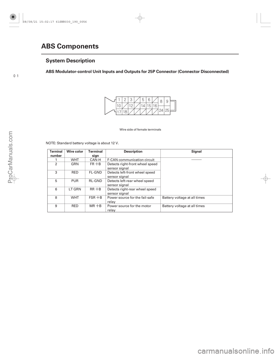
ABS Modulator-control Unit Inputs and Outputs for 25P Connector (Connector Disconnected)
TerminalnumberWire color Terminal sign Description Signal
19-56ABS Components
System Description
NOTE: Standard battery voltage is about 12 V.
1 WHT CAN-H F-CAN communication circuit
2 GRN FR B Detects right-front wheel speed sensor signal
3 RED FL-GND Detects left-front wheel speed sensor signal
5 PUR RL-GND Detects left-rear wheel speed sensor signal
6 LT GRN RR B Detects right-rear wheel speed sensor signal
8 WHT FSR B Power source for the fail-safe relay Battery voltage at all times
9 RED MR B Power source for the motor relay Battery voltage at all times
Wire side of female terminals
08/08/21 15:02:17 61SNR030_190_0056
ProCarManuals.com
DYNOMITE -2009-
Page 1550 of 2893
�•�•�•
�´
�´
�•�•�•
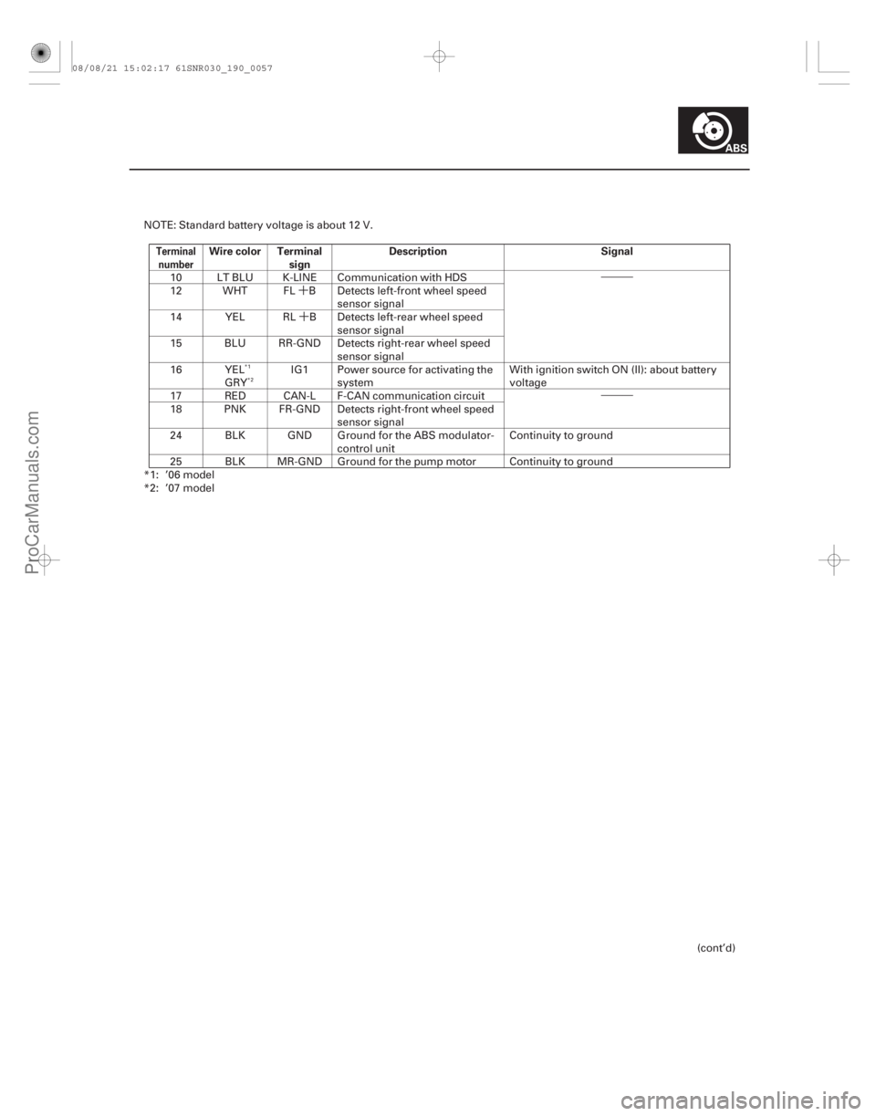
TerminalnumberWire color Terminal sign Description Signal
19-57
NOTE: Standard battery voltage is about 12 V.
10 LT BLU K-LINE Communication with HDS
12 WHT FL B Detects left-front wheel speed sensor signal
14 YEL RL B Detects left-rear wheel speed sensor signal
15 BLU RR-GND Detects right-rear wheel speed sensor signal
16 YEL GRY IG1 Power source for activating the
system With ignition switch ON (II): about battery
voltage
17 RED CAN-L F-CAN communication circuit
18 PNK FR-GND Detects right-front wheel speed sensor signal
24 BLK GND Ground for the ABS modulator- control unit Continuity to ground
25 BLK MR-GND Ground for the pump motor Continuity to ground
*1: ’06 model
*2: ’07 model
(cont’d)
*1*2
08/08/21 15:02:17 61SNR030_190_0057
ProCarManuals.com
DYNOMITE -2009-
Page 1551 of 2893
���
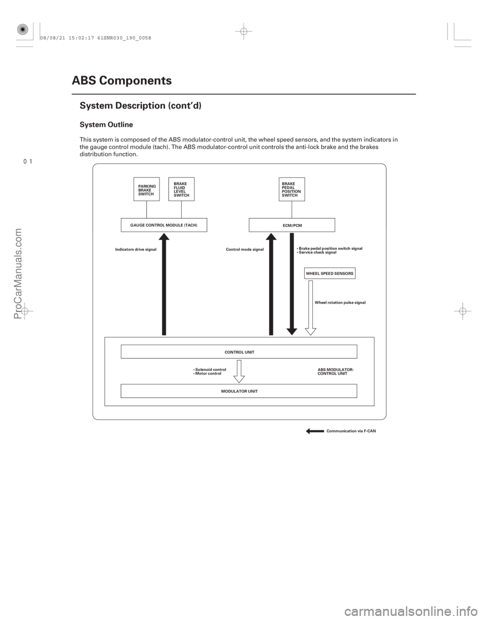
System Outline
19-58ABS Components
System Description (cont’d)
ECM/PCM
WHEEL SPEED SENSORS
Control mode signal
Indicators drive signal Brake pedal position switch signal
Service check signal
Wheel rotation pulse signal
CONTROL UNIT
MODULATOR UNIT ABS MODULATOR-
CONTROL UNIT
Solenoid control
Motor control
Communication via F-CAN
PARKING
BRAKE
SWITCH
BRAKE
FLUID
LEVEL
SWITCH BRAKE
PEDAL
POSITION
SWITCH
GAUGE CONTROL MODULE (TACH)
This system is composed of the ABS modulator-control unit, the wheel speed sensors, and the system indicators in
the gauge control module (tach). The ABS modulator-control unit controls the anti-lock brake and the brakes
distribution function.
08/08/21 15:02:17 61SNR030_190_0058
ProCarManuals.com
DYNOMITE -2009-
Page 1552 of 2893

����
����
ABS Features
Grip force of tire and road surface
Main control
19-59
TARGET SLIP RATEROTATIONAL
DIRECTION
RADIAL
DIRECTION
OF THE
ROTATIONAL
DIRECTION
SLIP RATE
COEFFICIENT OF
FRICTION
LEFT-REAR
WHEEL SPEED
SENSOR
RIGHT-REAR
WHEEL SPEED
SENSOR
LEFT-FRONT
WHEEL SPEED
SENSOR RIGHT-FRONT
WHEEL SPEED
SENSOR Select Low
Speed Wheel
Detect
Vehicle Speed
Drive
SolenoidRIGHT-REAR
SOLENOID
LEFT-REAR
SOLENOID
RIGHT-FRONT
SOLENOID
LEFT-FRONT
SOLENOID
CONTROL UNIT
ABS
Control
Reference
Slip Rate
Drive
Solenoid
ABS
Control
Drive
Solenoid
ABS
Control
Drive
Solenoid
ABS
Control
RIGHT-FRONT
LEFT-FRONT
Detect
Wheel Speed
Detect
Slip Rate
RIGHT-REAR
LEFT-REAR Detect
Slip Rate
Detect
Slip Rate
Detect
Slip Rate
Detect
Wheel Speed
Detect
Wheel Speed
Detect
Wheel Speed
Without ABS, when the brake pedal is pressed while driving, the wheels sometimes lock before the vehicle comes to a
stop. In such an event, the maneuverability of the vehicle is reduced if the front wheels are locked, and the stability of
the vehicle is reduced if the rear wheels are locked, creating an extremely unstable condition. With ABS, the system
precisely controls the slip rate of the wheels to ensure maximum grip force from the tires, and it thereby ensures
maneuverability and stability of the vehicle. The ABS calculates the slip rate of the wheels based on the four wheel
speeds, and then it controls the brake fluid pressure to reach the target slip rate.
The control unit detects the wheel speed based on the wheel speed sensor signals it receives, then it calculates the
vehicle speed based on the detected wheel speed. The control unit detects the vehicle speed during deceleration
based on the wheel speeds.
The control unit calculates the slip rate of each wheel, and transmits the control signal to the modulator unit solenoid
valve when the slip rate is high.
The hydraulic control has three modes: Pressure intensifying, pressure reducing, and pressure retaining.
(cont’d)
08/08/21 15:02:17 61SNR030_190_0059
ProCarManuals.com
DYNOMITE -2009-
Page 1553 of 2893

REAR WHEEL
BRAKE PRESSURE
With EBD under HEAVY LOAD
at REAR WHEELS
With EBD under LIGHT LOAD
at REAR WHEELS
Without EBD
FRONT WHEEL")
����
EBD Features
19-60ABS Components
System Description (cont’d)
REAR WHEEL
BRAKE PRESSURE
With EBD under HEAVY LOAD
at REAR WHEELS
With EBD under LIGHT LOAD
at REAR WHEELS
Without EBD
FRONT WHEEL BRAKE PRESSURE
The electronic brake distribution (EBD) feature helps control vehicle braking by adjusting the rear brake force in
accordance with the rear wheel load before the ABS operates. Based on the wheel speed sensor signals, the control
unit uses the modulator to control the rear brakes individually. When the rear wheel speed is less than the front wheel
speed, the ABS modulator-control unit retains the current rear brake fluid pressure by closing the inlet valve in the
modulator. As the rear wheel speed increases, and approaches the front wheel speed, the ABS modulator-control unit
increases the rear brake fluid pressure by momentarily opening the inlet valve. This whole process is repeated very
rapidly. While this is happening, kickback may be felt at the brake pedal.
08/08/21 15:02:18 61SNR030_190_0060
ProCarManuals.com
DYNOMITE -2009-
Page 1554 of 2893

OUT: OUTLET SOLENOID")
����
Modulator Unit
ModeInlet Solenoid
Valve Outlet Solenoid
Valve Brake Fluid
19-61
MODULATOR UNIT
RESERVOIR
RL
FR
FL
RR
MASTER CYLINDER
IN: INLET SOLENOID VALVE (NORMALLY OPEN)
OUT: OUTLET SOLENOID VALVE (NORMALLY CLOSED)
MOTOR
PUMP
IN IN
OUT IN
OUT IN
PUMP RESERVOIR
DAMPING
CHAMBER
OUT OUT
The ABS modulator consists of the inlet solenoid valve, the outlet solenoid valve, the reservoir, the pump, the pump
motor, and the damping chamber. The modulator reduces the caliper fluid pressure directly. It is a circulating-type
modulator because the brake fluid circulates through the caliper, the reservoir, and the master cylinder. The hydraulic
control has three modes; pressure intensifying, pressure retaining, and pressure reducing. The hydraulic circuit is an
independent four channel type; one channel for each wheel.
Pressure intensifying mode open closed Master cylinder fluid is pumped out
to the caliper.
Pressure retaining mode closed closed Caliper fluid is retained by the inlet and outlet valves.
Pressure reducing mode closed open Caliper fluid flows through the outlet valve to the reservoir.
The motor pumps the reservoir
fluid through the damping
chamber to the master cylinder .
: The motor will keep running until the operation of the one anti-lock brake control is finished with the first pressure reducing mode.
08/08/21 15:03:11 61SNR030_190_0061
ProCarManuals.com
DYNOMITE -2009-
Page 1556 of 2893
�����
�´�´
�´
�´ �´
�´
�´
19-63
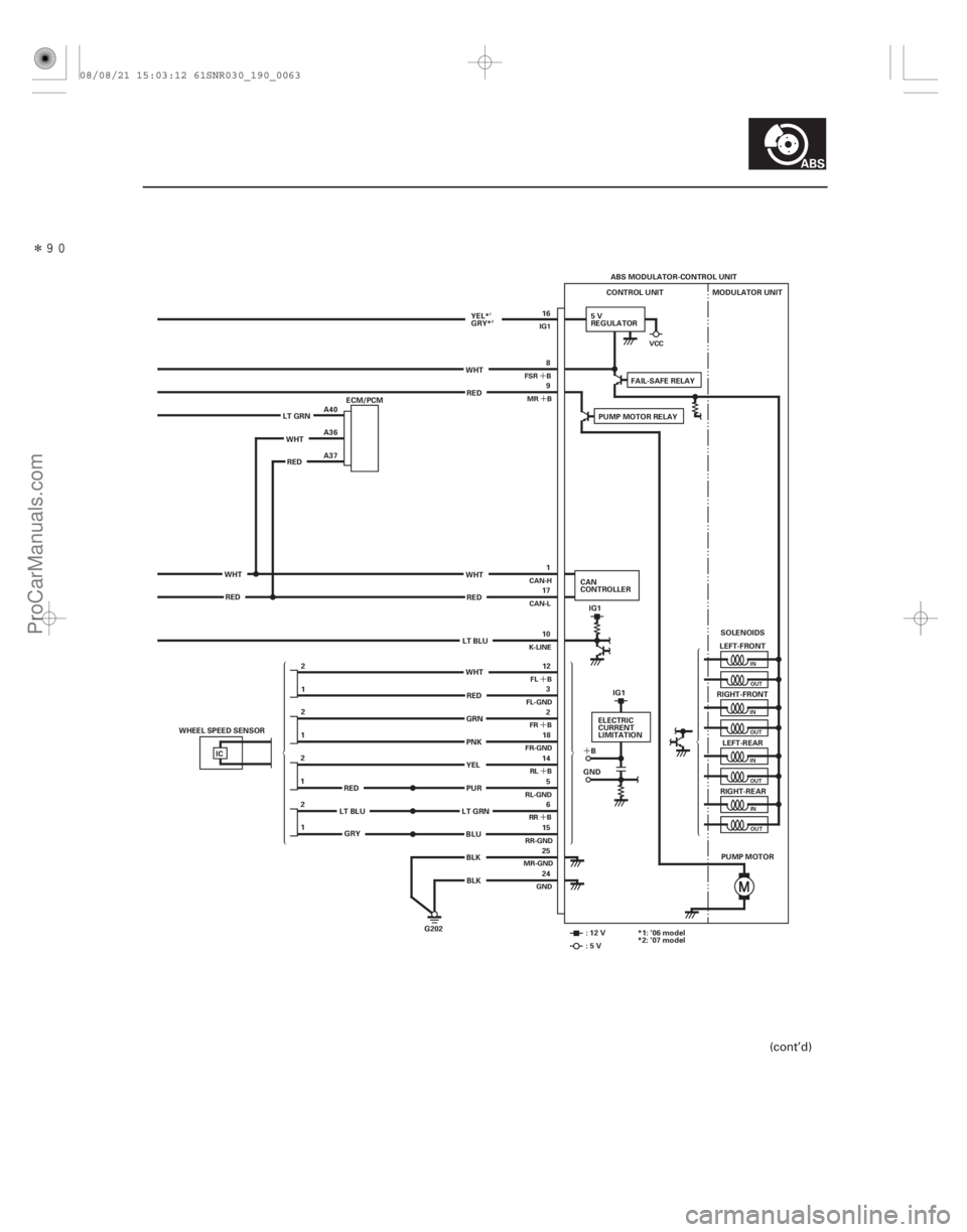
ABS MODULATOR-CONTROL UNIT
CONTROL UNIT MODULATOR UNIT
LEFT-FRONT
RIGHT-FRONT LEFT-REAR
RIGHT-REAR
PUMP MOTOR
G202 SOLENOIDS
8
9
12 3
2
18
14 5
6
15
25
24 1
17
10 16
WHT RED
WHT GRN
PNK
PUR YELBLK
BLK
LT GRN
IC
12
1
2
2
1
1 2 LT BLU
REDRED
ECM/PCM
WHT RED A40
A36
A37
WHT RED LT GRN
5V
REGULATOR
CAN
CONTROLLER IG1
ELECTRIC
CURRENT
LIMITATION
B
GND IG1
:12V :5V
RED
LT BLU GRY PUMP MOTOR RELAY
FAIL-SAFE RELAY
WHT BLU YEL*
GRY*
WHEEL SPEED SENSOR *1: ’06 model
*2: ’07 model
INOUT
IN OUT
IN OUT
INOUT
VCC
FSR B MR B
FL B
FL-GND FR B
FR-GND
RL B
RR B
MR-GND GND
CAN-H
CAN-L
K-LINE IG1
RL-GND RR-GND
1 2
(cont’d)
08/08/21 15:03:12 61SNR030_190_0063
ProCarManuals.com
DYNOMITE -2009-