Page 1347 of 2893

36-02 EPS Control Unit Internal Circuit (INH Output Circuit) (Initial Diagnosis) (see page 17-39)
37-01 EPS Control Unit")
DTCDetection Item Note
17-24EPS Components
DTC Troubleshooting Index (cont’d)
36-02 EPS Control Unit Internal Circuit (INH Output Circuit) (Initial Diagnosis) (see page 17-39)
37-01 EPS Control Unit Internal Circuit (Step-up Circuit) (Initial Diagnosis) (see page 17-39)
51-01 Low/High Voltage for the Torque Sensor (VT1 and VT2) (Regular
Diagnosis) (see page 17-46)
51-02 Torque Sensor (VT3 Differential-amplification Function) (Regular Diagnosis) (see page 17-50)
51-03 Torque Sensor (VT1, VT2 Rapid-change) (Regular Diagnosis) (see page 17-50)
51-06 Torque Sensor (VT1, VT2 Average) (Regular Diagnosis) (see page 17-50)
51-07 Torque Sensor (VT1, VT2 Initial Check) (Initial Diagnosis) (see page 17-50)
61-04 Open/Short in the EPS Motor Harness (Steering Diagnosis) (see page 17-53)
71-01 EPS Motor Angle Sensor (SIN/COS Signals) (Steering Diagnosis) (see page 17-55)
71-02 EPS Motor Angle Sensor (Neutral Position Learning of SIN/COS) (Initial Diagnosis) (see page 17-55)
71-03 EPS Motor Angle Sensor (SIN/COS Signals) (Steering Diagnosis) (see page 17-55)
71-04 EPS Motor Angle Sensor (Check Signals) (Regular Diagnosis) (see page 17-58)
71-05 EPS Motor Angle Sensor (SIN/COS Signals Charging Amount) (Steering Diagnosis) (see page 17-55)
71-06 EPS Motor Angle Sensor (Neutral Position of SIN/COS) (Initial Diagnosis) (see page 17-55)
NOTE: Initial diagnosis: Done right after the engine starts and until the EPS indicator goes off.
Regular diagnosis: Done right after the initial diagnosis until the ignition switch is turned to LOCK (0).
Steering diagnosis: Done during regular diagnosis while turning steering wheel.
08/08/21 14:53:59 61SNR030_170_0025
ProCarManuals.com
DYNOMITE -2009-
Page 1350 of 2893
 (Connector disconnected)
Terminalnumber Wire color Terminal sign Description Signal
17-27
NOTE: Sta")
�•�•�•
�•�•�•
�•�•�•
����EPS Control Unit Inputs and Outputs for Connector D (28P) (Connector disconnected)
Terminalnumber Wire color Terminal sign Description Signal
17-27
NOTE: Standard battery voltage is 12 V.
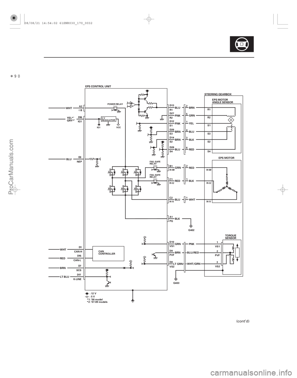
1WHTCAN-H (CAN-HI) CAN communication circuit
3BLUNEP (Engine pulse) Detects tachometer signal With engine running: pulses
7 BRN SCS (Service check signal) Detects service check
connector signal With service check signal not grounded: battery voltage
8 LT GRN VS2 (Voltage sensor 2) Detects torque sensor
signal
9 BRN PVF (Voltage fade) Drives the torque sensor
10 GRN VS1 (Voltage sensor 1) Detects torque sensor
signal
12 PNK S1 (Signal 1) Detects motor angle sensor
signal
13 BLU R1 (EPS Motor angle
sensor 1) Detects motor angle sensor
signal
14 BRN S2 (Signal 2) Detects motor angle sensor
signal
15 RED CAN-L (CAN-LO) CAN communication circuit
16 YEL GRYIG1
(Ignition 1) Power source for activating
the system With ignition switch ON (II): battery voltage
17 LT BLU K-LINE (Data link connector) Communicates with HDS With service check signal opened: about 5.0 V
26 BRN S3 (Signal 3) Detects motor angle sensor
signal
27 PNK R2 (EPS Motor angle
sensor 2) Detects motor angle sensor
signal
28 BLU S4 (Signal 4) Detects motor angle sensor
signal
1: ’06 model
2: ’07-09 models
(cont’d)
12
Wire side of female terminals
08/08/21 14:54:00 61SNR030_170_0028
ProCarManuals.com
DYNOMITE -2009-
Page 1351 of 2893

GAUGE CONTROL MODULE
ECM
Indicator drive signal
EPS CONTROL UNITEPS MOTOR
EPS MOTOR ANGLE SENSOR TORQUE SENSOR Motor drive sign")
����
System Outline
17-28EPS Components
System Description (cont’d)
GAUGE CONTROL MODULE
ECM
Indicator drive signal
EPS CONTROL UNITEPS MOTOR
EPS MOTOR ANGLE SENSOR TORQUE SENSOR Motor drive signal
Motor angle signal Torque signal Idle control
demand
Communication via F-CAN
Vehicle
speed
signal
Engine
speed
signal
The power steering system adopts the electric power steering assisting for the control force of the steering wheel in
the driving force of the electric motor.
The EPS control unit is doing an appropriate steering force control according to the running situation of the vehicle (at
time of low speed, lightness, by the control of emphasis and high-speed running time, control with the steady weight
and the control which will be switched from low speed to high speed smoothly later) by the EPS motor.
The EPS control unit is designed for use with an automotive power steering for the primary purpose of controlling the
assist motor (brushless motor) for the power steering by using as inputs the steering torque signals received from the
‘‘steering torque sensor’’ installed in the steering gearbox as well as the speed signals received from the ‘‘vehicle
speed sensor’’ installed in the vehicle. In addition to the above function, the EPS control unit also provides the failsafe
function, self diagnosis function and motor output limiting function.
08/08/21 14:54:00 61SNR030_170_0029
ProCarManuals.com
DYNOMITE -2009-
Page 1352 of 2893
�����
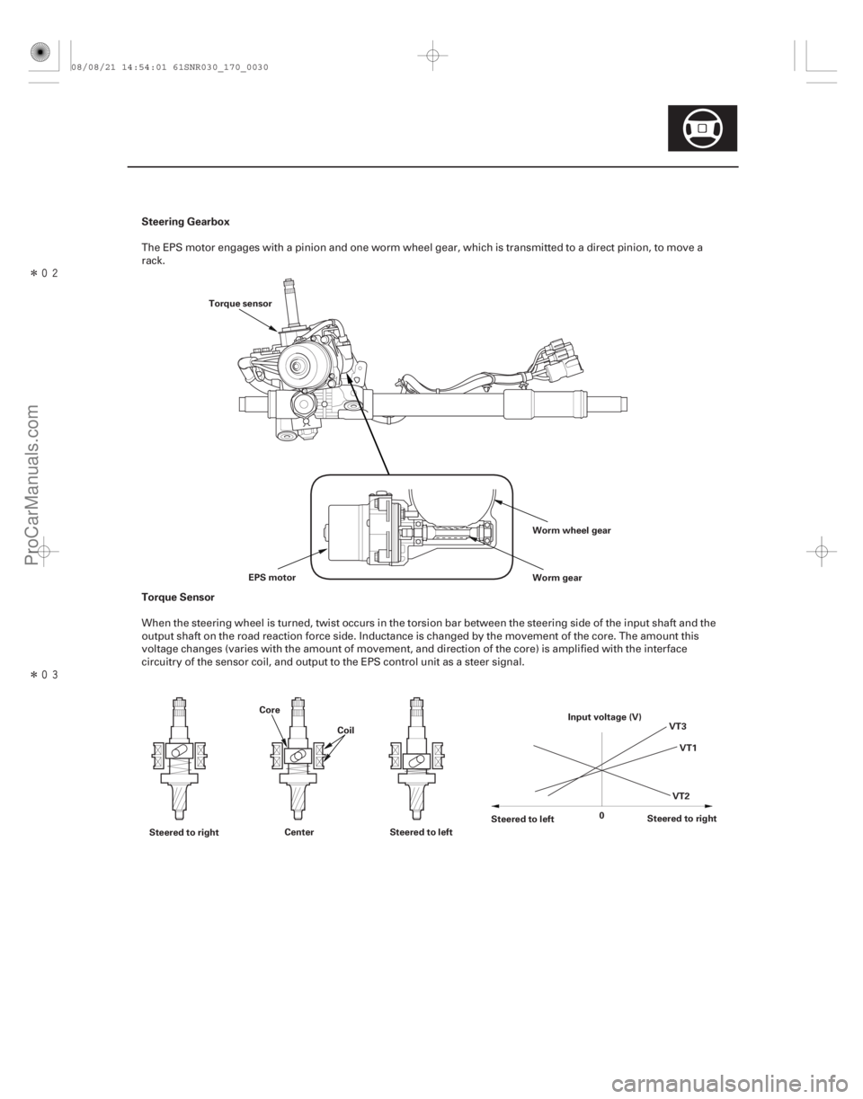
�����Steering Gearbox
Torque Sensor
17-29
Worm wheel gear
Worm gear
EPS motor
Torque sensor
Steered to right Center Steered to left Steered to left
Steered to right
0 VT1
VT3
VT2
Input voltage (V)
Core
Coil
The EPS motor engages with a pinion and one worm wheel gear, which is transmitted to a direct pinion, to move a
rack.
When the steering wheel is turned, twist occurs in the torsion bar between the steering side of the input shaft and the
output shaft on the road reaction force side. Inductance is changed by the movement of the core. The amount this
voltage changes (varies with the amount of movement, and direction of the core) is amplified with the interface
circuitry of the sensor coil, and output to the EPS control unit as a steer signal.
08/08/21 14:54:01 61SNR030_170_0030
ProCarManuals.com
DYNOMITE -2009-
Page 1354 of 2893
�����
�´
17-31
EPS CONTROL UNIT
WHT
BLU
WHT
RED
BRN STEERING GEARBOX
PNK
PNK BLU
BRN GRN
YEL
BLU EPS MOTOR
ANGLE SENSOR
BRN
BLU BLK
BRN
RED
BLU RED GRN
WHT
BLK RED
BLK
GRN
BRN
LT GRN TORQUE
SENSOR
PNK
BLU/RED
WHT/GRN
LT BLU YEL*
GRY*
EPS MOTOR
5V
REGULATOR
FAIL-SAFE
RELAY
POWER RELAY
FAIL-SAFE
RELAY
IG1 VCC
B
A2
IG1 D16
D3
NEP
D1
D15
D7
D17
SCS
CAN-L
CAN-H
K-LINE D13
R2 R1
S3 S1 5
2
4
1
S4 S2 6 3
H-V H-U H-W 2
1
1
PG D12 D27
D26
D14
D28
B1
C1
C2
A1
VS1 D10
PVF D9
VS2 D8
CAN
CONTROLLER R2
R1
S3 S1
S4 S2
H-V H-U
H-W
VS1
PVFVS2 1
2
3
G402
G403
:12V
:5V
*1: ’06 model
*2: ’07-09 models
1
2
(cont’d)
08/08/21 14:54:02 61SNR030_170_0032
ProCarManuals.com
DYNOMITE -2009-
Page 1355 of 2893
���
17-32EPS Components
Circuit Diagram (cont’d)
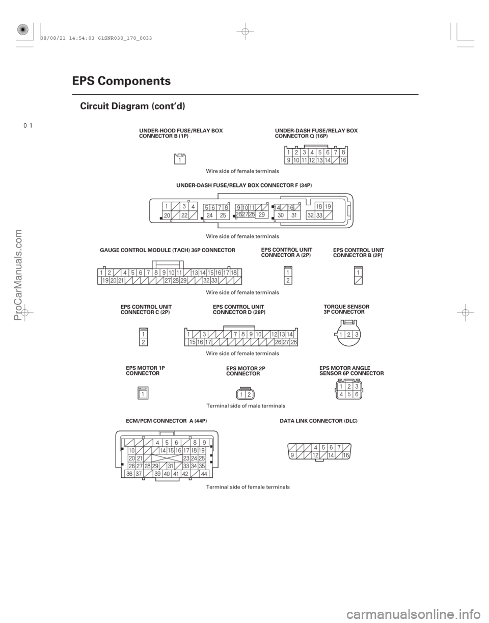
EPS CONTROL UNIT
CONNECTOR A (2P)
EPS CONTROL UNIT
CONNECTOR B (2P)
DATA LINK CONNECTOR (DLC)
GAUGE CONTROL MODULE (TACH) 36P CONNECTOR
UNDER-DASH FUSE/RELAY BOX CONNECTOR F (34P)
EPS CONTROL UNIT
CONNECTOR D (28P)
EPS CONTROL UNIT
CONNECTOR C (2P) TORQUE SENSOR
3P CONNECTOR
UNDER-DASH FUSE/RELAY BOX
CONNECTOR Q (16P)
UNDER-HOOD FUSE/RELAY BOX
CONNECTOR B (1P)
ECM/PCM CONNECTOR A (44P) EPS MOTOR 1P
CONNECTOR EPS MOTOR 2P
CONNECTOREPS MOTOR ANGLE
SENSOR 6P CONNECTOR
Wire side of female terminals
Wire side of female terminals
Terminal side of male terminals
Terminal side of female terminals
Wire side of female terminals
Wire side of female terminals
08/08/21 14:54:03 61SNR030_170_0033
ProCarManuals.com
DYNOMITE -2009-
Page 1369 of 2893
�����(�#���������� ����������������
���
�������)����
�µ
�µ
�µ
�µ �µ
�µ
�µ
�µ
DTC 35-03:
DTC 35-05: DTC 51-01:
YES
NO
YES
NO YES
NO
YES
N")
�µ
�µ
�(�#�'��������� �������������'���������������)�����(�#�'��������� �������������'���
���
�������)����
�µ
�µ
�µ
�µ �µ
�µ
�µ
�µ
DTC 35-03:
DTC 35-05: DTC 51-01:
YES
NO
YES
NO YES
NO
YES
NO
17-4617-46EPS Components
DTC Troubleshooting (cont’d)
EPS Control Unit Internal Circuit
(EPS CPU) (Internal Diagnosis)
EPS Control Unit Internal Circuit
(EPS Motor/EPS CPU) (Internal Diagnosis) Low/High Voltage for the Torque
Sensor (VT1 and VT2) (Regular Diagnosis)
1. Turn the ignition switch to ON (II).
2. Clear the DTC with the HDS.
3. Turn the ignition switch to LOCK (0).
4. Turn the ignition switch to ON (II).
Go to step 5.
Check for loose terminals or poor connections.
If the connections are good, the system is OK at
this time.
5. Start the engine.
6. Wait 10 seconds or more.
7. Check for DTCs with the HDS.
Check for loose terminals in the EPS control
unit connectors, and repair if necessary. If no poor
connections are found, replace the EPS control unit
(see page 17-84).
Troubleshoot the indicated DTC. If there are
no DTCs, the system is OK at this time. 1. Turn the ignition switch to LOCK (0).
2. Connect the HDS to the data link connector (DLC).
3. Turn the ignition switch to ON (II).
4. Check the ADVT1 in the DATA LIST with the HDS.
Go to step 5.
Go to step 6.
5. Check the ADVT2 in the DATA LIST with the HDS.
Check for loose terminals or poor
connections. If the connections are good, the
system is OK at this time.
Go to step 6.
6. Turn the ignition switch to LOCK (0).
Does t he E PS i nd i cat or come on?
I s DT C 35 -03 or 35 -05 i nd i cat ed ? Is the v oltage at 0.90 3.55 V ?
Is the voltage at 1.02 3.73 V ?
08/08/21 14:54:34 61SNR030_170_0047
ProCarManuals.com
DYNOMITE -2009-
Page 1371 of 2893

EPS CONTROL UNIT CONNECTOR D (28P)
PVF (BRN) EPS CONTROL UNIT CONNECTOR D (28P)
PVF (BRN)
10. Check for contin")
�������
�µ
�µ �µ
�µ
YES
NO
YES
NO
17-48EPS Components
DTC Troubleshooting (cont’d)
EPS CONTROL UNIT CONNECTOR D (28P)
PVF (BRN) EPS CONTROL UNIT CONNECTOR D (28P)
PVF (BRN)
10. Check for continuity between EPS control unitconnector D (28P) terminal No. 9 and body ground.
Go to step 11.
Check for loose terminals in the EPS control
unit connectors, and repair if necessary. If no poor
connections are found, replace the EPS control unit
(see page 17-84). 11. Disconnect the torque sensor 3P connector from
the steering gearbox.
12. Check for continuity between EPS control unit connector D (28P) terminal No. 9 and body ground.
Repair short to body ground in the wire
between the torque sensor and the EPS control
unit.
Faulty torque sensor (short in the sensor
internal circuit), replace the steering gearbox
(see page 17-65).
Wire side of female terminals
Wire side of female terminals
Is there continuity?Is there continuity?
08/08/21 14:54:34 61SNR030_170_0049
ProCarManuals.com
DYNOMITE -2009-