Page 1276 of 2893

C
B A
6x1.0mm
14 N·m
(1.4 kgf·m,
10 lbf·ft) A
D
E
B
C
F
10. Lubricate the threads of the shafts, new lock")
�µ�µ
�����
���
�����
����
14-351
A
B
D
C
AB 6x1.0mm
14 N·m
(1.4 kgf·m, 10 lbf·ft)
C
B A
6x1.0mm
14 N·m
(1.4 kgf·m,
10 lbf·ft) A
D
E
B
C
F
10. Lubricate the threads of the shafts, new locknuts and new conical spring washers with ATF.
11. Install new conical spring washers (A) with facing stamped mark side up in the direction shown, and
install a new mainshaft locknut (B), a new
countershaft locknut (C), and a new secondary
shaft locknut (D).
12. Tighten the locknuts to 167 N·m (17.0 kgf·m, 123 lbf·ft).
NOTE: Be sure to install the conical spring washers in the direction shown.
Use a torque wrench to tighten the locknut. Do not use an impact wrench.
Countershaft and secondary shaft locknuts have left-hand threads.
13. Remove the mainshaft holder from the mainshaft.
14. Stake the locknuts into the shafts to a depth (A) of 0.7 1.3 mm (0.03 0.05 in.) using a 3.5 mm punch
(B). 15. Install the control lever (A) on the selector control
shaft (B), and install the bolt with a new lock
washer (C), then bend the lock tab of the lock
washer against the bolt head.
16. Set the park lever in the P position, then check that the park pawl (A) engages the park gear (B).
17. If the park pawl does not engage fully, check the distance (C) between the pawl shaft (D) and the
park lever roller pin (E) (see page 14-292).
18. Tighten the lock bolt, and bend the lock tab of the lock washer (F) against the bolt head.
(cont’d)
Replace.
Replace.
Left-hand threads
Replace.
Left-hand threads
Replace.
Replace.
08/08/21 14:52:36 61SNR030_140_0353
ProCarManuals.com
DYNOMITE -2009-
Page 1277 of 2893

B
A
E
8x1.25mm
28 N·m
(2.9 kgf·m,
21 lbf·ft) D
E
B F
6x1.0mm
12 N·m
(1.2 kgf·m,
8.7 lbf·ft)
6x1.0mm
12 N�")
����
����� �����
����
14-352Transmission End Cover
End Cover Installation (cont’d)
B
A
E
8x1.25mm
28 N·m
(2.9 kgf·m,
21 lbf·ft) D
E
B F
6x1.0mm
12 N·m
(1.2 kgf·m,
8.7 lbf·ft)
6x1.0mm
12 N·m
(1.2 kgf·m,
8.7 lbf·ft) C
A
G A
AB
C
D
19. Install the ATF feed pipe (A) into the idler gear shaft, and install the ATF lubrication pipe (B) into the
transmission housing.
20. Install a new gasket (A) on the transmission housing, and install the two dowel pins (B) and new
O-rings (C) over the top of the ATF feed pipes.
21. Install the end cover (D), and tighten the three specialbolts(E)andthe6x1.0mmbolts(F)
(12 bolts).
22. Install the harness clamp bracket (G) on the end cover. 23. Set the selector control shaft (A) to the N position
by turning the control lever on the torque converter
side.
NOTE: Do not squeeze the end of the selector
control shaft tips together when turning the
selector control shaft. If the tips are squeezed
together it will cause a faulty shift position signal or
position due to the play between the selector
control shaft and the transmission range switch.
24. Align the cutouts (A) on the rotary-frame with the neutral positioning cutouts (B) on the transmission
range switch (C), then put a 2.0 mm (0.08 in.) feeler
gauge blade (D) in the cutouts to hold in the N
position.
NOTE: Be sure to use a 2.0 mm (0.08 in.) blade or
equivalent to hold the transmission range switch in
the N position.
Replace.
Replace.
08/08/21 14:52:37 61SNR030_140_0354
ProCarManuals.com
DYNOMITE -2009-
Page 1283 of 2893
���
�������
����
�(�#�'�������
���
�����
�
���
�������
� �����)����
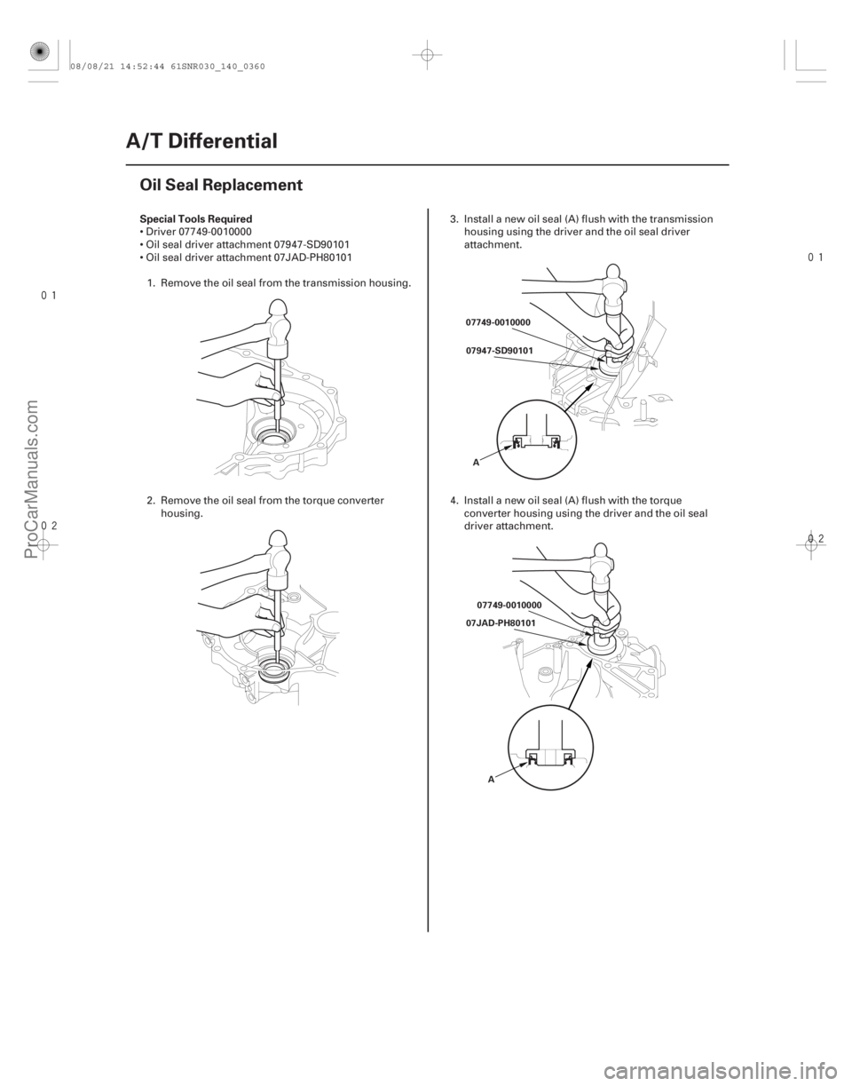
Special Tools Required
14-358
A/T Differential
Oil Seal Replacement
07749-0010000
07947-SD90101
A
07749-0010000
07JAD-PH80101
A
Driver 07749-0010000
Oil seal driver attachment 07947-SD90101
Oil seal driver attachment 07JAD-PH801011. Remove the oil seal from the transmission housing.
2. Remove the oil seal from the torque converter housing. 3. Install a new oil seal (A) flush with the transmission
housing using the driver and the oil seal driver
attachment.
4. Install a new oil seal (A) flush with the torque converter housing using the driver and the oil seal
driver attachment.
08/08/21 14:52:44 61SNR030_140_0360
ProCarManuals.com
DYNOMITE -2009-
Page 1284 of 2893
����
Special Tools Required
’06 Model ’07-09 Models
14-359
Carrier Bearing Outer Race Replacement
A B C
D E
A
D E
B C
A
B
C
Driver")
���
���
����
�(�#�'�������
���
�����
�
���
�������
� �����)����
Special Tools Required
’06 Model ’07-09 Models
14-359
Carrier Bearing Outer Race Replacement
A B C
D E
A
D E
B C
A
B
C
Driver 07749-0010000
Attachment, 78 x 80 mm 07NAD-PX40100
Attachment, 72 x 75 mm 07746-0010600
NOTE: Replace the bearing with a new one whenever the outer race is replaced. The bearing and the bearing
outer race should be replaced as a set.
Do not use the thrust shim on the torque converter housing.
Adjust the bearing preload (see page 14-361) after replacing the carrier bearing and the carrier bearing
outer race.
Coat all parts with ATF during installation.
1. Remove the bearing outer race (A), the 76.2 mm thrust washer (B), and the 76 mm thrust shim (C)
from the transmission housing (D) by heating the
housing to about 100 °C (212 °F) with a heat gun (E).
Do not heat the housing more than 100 °C (212 °F).
2. Remove the bearing outer race (A) and the 80 mmthrust washer (B) from the torque converter
housing (C) by hand.
(cont’d)
08/08/21 14:53:03 61SNR030_140_0361
ProCarManuals.com
DYNOMITE -2009-
Page 1286 of 2893
���� Special Tools Required ’06 Model
14-36114-361
Carrier Bearing Preload Inspection
A B
C 07749-0010000
07NAD-PX40100 A B C
D E
5. Insta")
����
�������
�(�#�'�������
���
�����
�
���
�����
�
�"�����)���� Special Tools Required ’06 Model
14-36114-361
Carrier Bearing Preload Inspection
A B
C 07749-0010000
07NAD-PX40100 A B C
D E
5. Install the 80 mm thrust washer (A) and the carrier
bearing outer race (B) in the torque converter
housing (C).
6. Install the carrier bearing outer race securely in the torque converter housing so there is no clearance
between the carrier bearing outer race, the 80 mm
thrust washer, and the torque converter housing
using the driver and the 78 x 80 mm attachment. Driver 07749-0010000
Attachment, 72 x 75 mm 07746-0010600
Preload inspection tool 07HAJ-PK40201
NOTE:
Replace the carrier bearing with a new one whenever the carrier bearing outer race is replaced. The carrier
bearing and the carrier bearing outer race should be
replaced as a set.
Do not use the 76 mm thrust shim on the torque converter housing.
Adjust the carrier bearing preload, when replacing the transmission housing, the torque converter
housing, the differential carrier, the carrier bearing,
the carrier bearing outer race, or the 76 mm thrust
shim.
1. Remove the carrier bearing outer race (A), the 76.2 mm thrust washer (B), and the 76 mm thrust
shim (C) from the transmission housing (D) by
heating the housing to about 100 °C (212 °F) with a
heat gun (E). Do not heat the housing more than
100 °C (212 °F).
(cont’d)
08/08/21 14:53:05 61SNR030_140_0363
ProCarManuals.com
DYNOMITE -2009-
Page 1287 of 2893
���� Special Tools Required ’06 Model
14-36114-361
Carrier Bearing Preload Inspection
A B
C 07749-0010000
07NAD-PX40100 A B C
D E
5. Insta")
����
�������
�(�#�'�������
���
�����
�
���
�����
�
�"�����)���� Special Tools Required ’06 Model
14-36114-361
Carrier Bearing Preload Inspection
A B
C 07749-0010000
07NAD-PX40100 A B C
D E
5. Install the 80 mm thrust washer (A) and the carrier
bearing outer race (B) in the torque converter
housing (C).
6. Install the carrier bearing outer race securely in the torque converter housing so there is no clearance
between the carrier bearing outer race, the 80 mm
thrust washer, and the torque converter housing
using the driver and the 78 x 80 mm attachment. Driver 07749-0010000
Attachment, 72 x 75 mm 07746-0010600
Preload inspection tool 07HAJ-PK40201
NOTE:
Replace the carrier bearing with a new one whenever the carrier bearing outer race is replaced. The carrier
bearing and the carrier bearing outer race should be
replaced as a set.
Do not use the 76 mm thrust shim on the torque converter housing.
Adjust the carrier bearing preload, when replacing the transmission housing, the torque converter
housing, the differential carrier, the carrier bearing,
the carrier bearing outer race, or the 76 mm thrust
shim.
1. Remove the carrier bearing outer race (A), the 76.2 mm thrust washer (B), and the 76 mm thrust
shim (C) from the transmission housing (D) by
heating the housing to about 100 °C (212 °F) with a
heat gun (E). Do not heat the housing more than
100 °C (212 °F).
(cont’d)
08/08/21 14:53:05 61SNR030_140_0363
ProCarManuals.com
DYNOMITE -2009-
Page 1289 of 2893
��������
14-363
07749-0010000
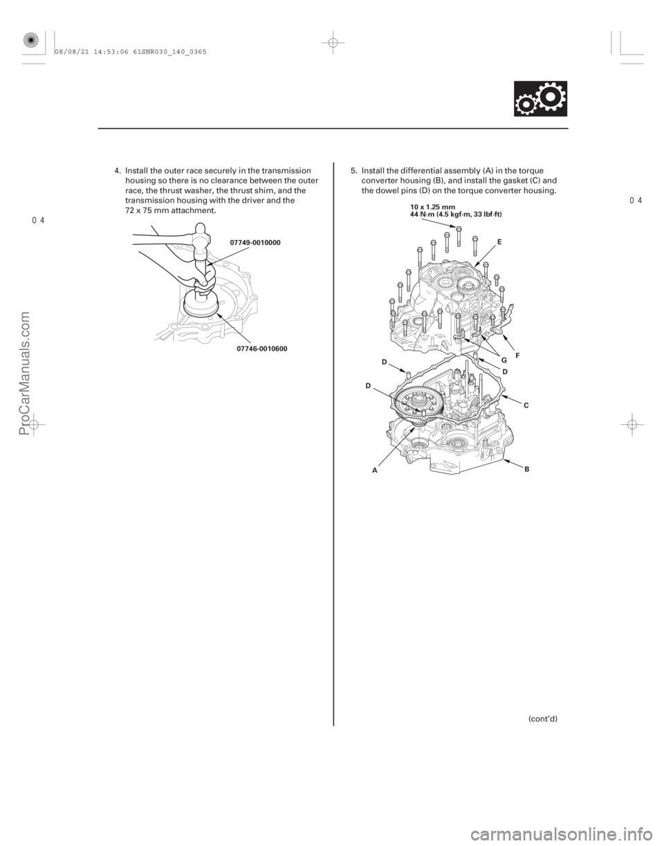
07746-0010600 10x1.25mm
44 N·m (4.5 kgf·m, 33 lbf·ft)
A B
C
D
E
F
G
D D
4. Install the outer race securely in the transmission
housing so there is no clearance between the outer
race, the thrust washer, the thrust shim, and the
transmission housing with the driver and the
72x75mmattachment. 5. Install the differential assembly (A) in the torque
converter housing (B), and install the gasket (C) and
the dowel pins (D) on the torque converter housing.
(cont’d)
08/08/21 14:53:06 61SNR030_140_0365
ProCarManuals.com
DYNOMITE -2009-
Page 1290 of 2893

Reused Bearings:
2.5 3.6 N·m (25 37 kgf·cm, 22 32 lbf·in.) THRUST SHIM, 76 mm
No. Part Num")
�µ
�µ�µ
���� �µ�µ �µ
�µ�µ �µ
Standard:
New Bearings:
2.7 3.9 N·m (28 40 kgf·cm, 24 35 lbf·in.)
Reused Bearings:
2.5 3.6 N·m (25 37 kgf·cm, 22 32 lbf·in.) THRUST SHIM, 76 mm
No. Part Number Thickness
(cont’d)
14-364A/T Differential
Carrier Bearing Preload Inspection (cont’d)
A
B
07HAJ-PK40201
6. Install the transmission housing (E), and install the mounting bolts (19 bolts) with the transmission
hanger (F) and the harness clamp brackets (G), then
tighten the bolts.
7. Rotate the differential assembly in both directions to seat the bearings.
8. Measure the starting torque of the differential assembly using the preload inspection tool, a
torque wrench (A), and a socket (B). Measure the
starting torque at normal room temperature in both
directions. 9. If the starting torque is out of standard, remove the
76 mm thrust shim, and select the thrust shim from
the following table. Install a new thrust shim and
recheck. To increase the starting torque, increase
the thickness of the 76 mm thrust shim. To
decrease the starting torque, decrease the
thickness of the 76 mm thrust shim. Changing the
thrust shim to the next size will increase or
decrease starting torque about 0.3 0.4 N·m
(3 4 kgf·cm, 2 3 lbf·in.).
S 41438-PX4-700 2.05 mm (0.081 in.)T 41439-PX4-700 2.10 mm (0.083 in.)
U 41440-PX4-700 2.15 mm (0.085 in.) A 41441-PK4-000 2.20 mm (0.087 in.)B 41442-PK4-000 2.25 mm (0.089 in.)
C 41443-PK4-000 2.30 mm (0.091 in.)
D 41444-PK4-000 2.35 mm (0.093 in.) E 41445-PK4-000 2.40 mm (0.094 in.)F 41446-PK4-000 2.45 mm (0.096 in.)
G 41447-PK4-000 2.50 mm (0.098 in.) H 41448-PK4-000 2.55 mm (0.100 in.) I 41449-PK4-000 2.60 mm (0.101 in.)
J 41450-PK4-000 2.65 mm (0.103 in.)
K 41451-PK4-000 2.70 mm (0.105 in.) L 41452-PK4-000 2.75 mm (0.107 in.)
M 41453-PK4-000 2.80 mm (0.110 in.) N 41454-PK4-000 2.85 mm (0.112 in.)
O 41455-PK4-000 2.90 mm (0.114 in.) P 41456-PK4-000 2.95 mm (0.116 in.)
Q 41457-PK4-000 3.00 mm (0.118 in.) R 41458-PK4-000 3.05 mm (0.120 in.)
0A 41428-PRP-000 1.55 mm (0.061 in.) 0B 41429-PRP-000 1.60 mm (0.063 in.)
0C 41430-PRP-000 1.65 mm (0.065 in.)
0D 41431-PRP-000 1.70 mm (0.067 in.) 0E 41432-PRP-000 1.75 mm (0.069 in.)0F 41433-PRP-000 1.80 mm (0.071 in.)
0G 41434-PRP-000 1.85 mm (0.073 in.) 0H 41435-PRP-000 1.90 mm (0.075 in.) 0I 41436-PRP-000 1.95 mm (0.077 in.)
0J 41437-PRP-000 2.00 mm (0.079 in.)
08/08/21 14:53:07 61SNR030_140_0366
ProCarManuals.com
DYNOMITE -2009-