Page 1126 of 2893
����
�µ
Stall Speed rpm:
Specification: 2,150 rpm
Service Limit: 2,000 2,300 rpm Problem Probable causes
14-210
Automatic Transmission
Stall Speed Te")
���
�(�#�'�������
���
���������������������������)����
�µ
Stall Speed rpm:
Specification: 2,150 rpm
Service Limit: 2,000 2,300 rpm Problem Probable causes
14-210
Automatic Transmission
Stall Speed Test
A
1. Make sure the transmission fluid is filled to the
proper level (see page 14-231).
2. Apply the parking brake, and block all four wheels.
3. Connect the HDS to the DLC (A) located under the driver’s side of the dashboard.
4. Turn the ignition switch to ON (II), and go to the A/T Data List. Make sure the HDS communicates with
the PCM. If it does not, go to the DLC circuit
troubleshooting (see page 11- 204).
5. Make sure the A/C switch is OFF.
6. Start the engine, and warm it up to normal operating temperature (the radiator fan comes on).
7. Shift to D while pressing the brake pedal firmly, then fully press the accelerator pedal for
6 to 8 seconds, and note the engine speed. Do not
move the shift lever or remove your foot off the
brake pedal while raising the engine speed.
8. Allow 2 minutes for cooling, then repeat the test in SandR.
NOTE: Do not test the stall speed for more than 10 seconds at a time.
The stall speed tests should be used for diagnostic purposes only.
Stall speed test results should be the same with the shift lever in D, S, and R.
Do not test the stall speed with the A/T oil pressure gauges installed. 9. If the stall speeds are out of the service limit, the
problems and probable causes are listed in the
table.
Stall speed rpm high
in D, S, and R
ATF pump output
low
Clogged ATF strainer
Regulator valve stuck
Slipping clutch
Stall speed rpm high
in R Slippage of 4th clutch
Stall speed rpm low
in D, S, and R Engine output low
Engine throttle valve
closed
Torque converter
one-way clutch
slipping
08/08/21 14:46:42 61SNR030_140_0212
ProCarManuals.com
DYNOMITE -2009-
Page 1130 of 2893

27. Bring the engine back to an idle, then apply the
brake pedal")
�µ�µ
�µ
Pressure Fluid Pressure
Standard Service Limit Problem Probable causes
14-214Automatic Transmission
Pressure Test (cont’d)
27. Bring the engine back to an idle, then apply the
brake pedal to stop the wheels from rotating.
28. Shift to R, then release the brake pedal. Measure the 4th clutch pressure at the 4th clutch pressure
inspection port (F) while holding the engine speed
at 2,000 rpm.
4th clutch
(F) in R 890 970 kPa
(9.1 9.9 kgf/cm ,
130 140 psi) 840 kPa
(8.6 kgf/cm ,
120 psi)
29. Turn the engine off, then disconnect the A/T oil pressure gauge from the 3rd, 4th, and 5th clutch
pressure inspection ports.
30. Install the sealing bolts in the 3rd, 4th, and 5th clutch pressure inspection ports with new sealing
washers, and tighten the bolts to 18 N·m (1.8 kgf·m,
13 lbf·ft). Do not reuse the old sealing washers. 31. If the pressures are out of the service limit, the
problems and probable causes are listed in the
table.
No or low line
pressure
Torque converter
ATF pump
Regulator valve
Torque converter
check valve
Clogged ATF strainer
No or low 1st clutch
pressure 1st clutch
O-rings
No or low 2nd clutch
pressure 2nd clutch
O-rings
No or low 3rd clutch
pressure 3rd clutch
O-rings
No or low 4th clutch
pressure 4th clutch
O-rings
No or low 5th clutch
pressure 5th clutch
O-rings
No or low 4th clutch
pressure in R Servo valve
4th clutch
O-rings
32. Install the splash shield.
33. Check the ATF level (see page 14-231).
22
08/08/21 14:46:43 61SNR030_140_0216
ProCarManuals.com
DYNOMITE -2009-
Page 1154 of 2893
�
��
�
������
���
14-238Automatic Transmission
Transmission Removal (cont’d)
A
BCC
B A
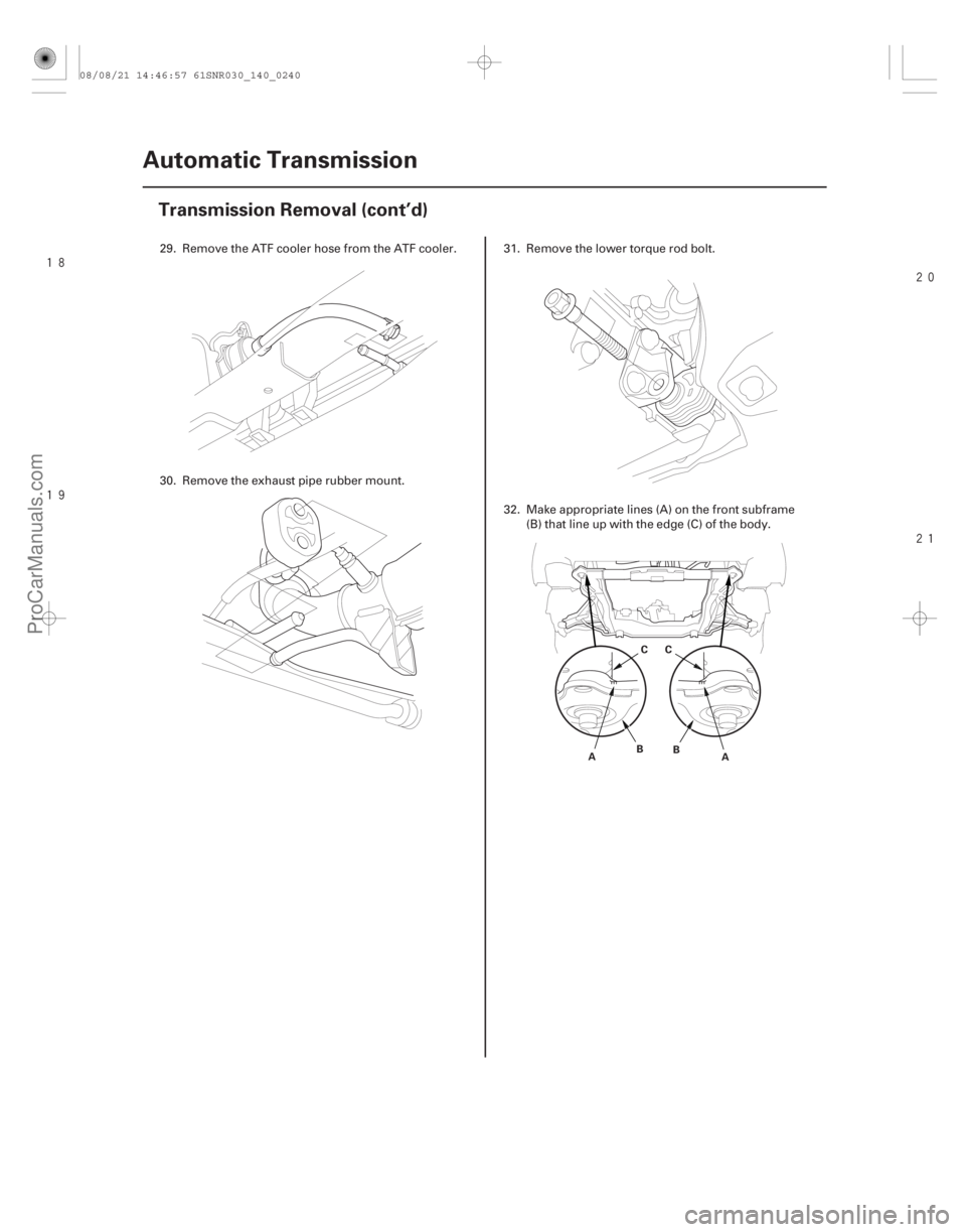
29. Remove the ATF cooler hose from the ATF cooler.
30. Remove the exhaust pipe rubber mount. 31. Remove the lower torque rod bolt.
32. Make appropriate lines (A) on the front subframe
(B) that line up with the edge (C) of the body.
08/08/21 14:46:57 61SNR030_140_0240
ProCarManuals.com
DYNOMITE -2009-
Page 1156 of 2893
����
��������
����
14-240Automatic Transmission
Transmission Removal (cont’d)
A
B
A B
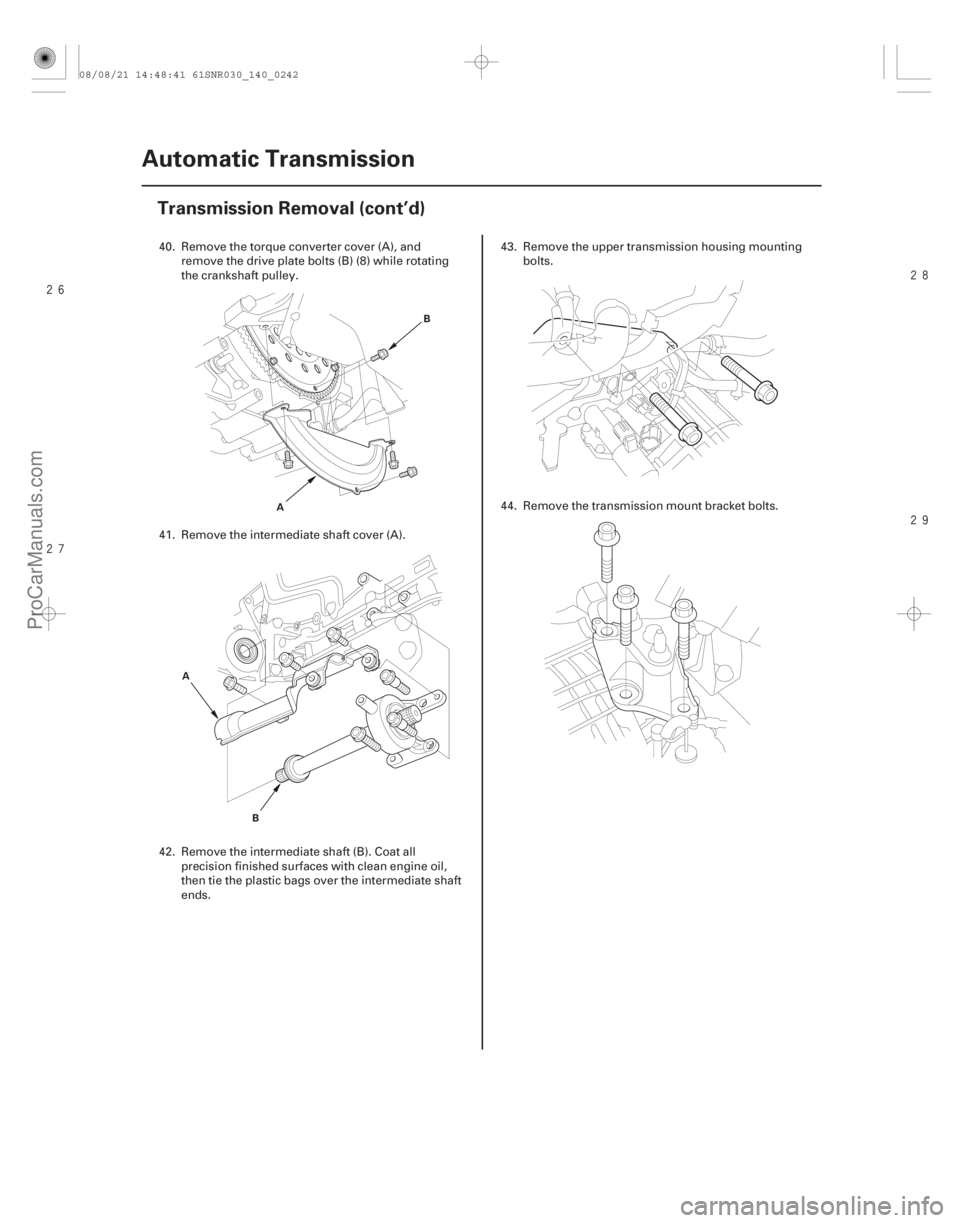
40. Remove the torque converter cover (A), andremove the drive plate bolts (B) (8) while rotating
the crankshaft pulley.
41. Remove the intermediate shaft cover (A).
42. Remove the intermediate shaft (B). Coat all precision finished surfaces with clean engine oil,
then tie the plastic bags over the intermediate shaft
ends. 43. Remove the upper transmission housing mounting
bolts.
44. Remove the transmission mount bracket bolts.
08/08/21 14:48:41 61SNR030_140_0242
ProCarManuals.com
DYNOMITE -2009-
Page 1157 of 2893
����
���
����
����
14-241
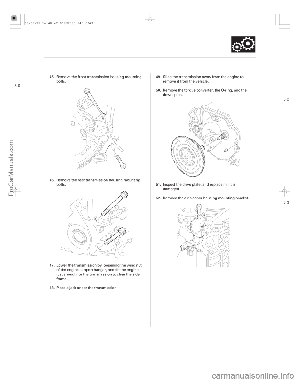
45. Remove the front transmission housing mounting
bolts.
46. Remove the rear transmission housing mounting bolts.
47. Lower the transmission by loosening the wing nut of the engine support hanger, and tilt the engine
just enough for the transmission to clear the side
frame.
48. Place a jack under the transmission. 49. Slide the transmission away from the engine to
remove it from the vehicle.
50. Remove the torque converter, the O-ring, and the dowel pins.
51. Inspect the drive plate, and replace it if it is damaged.
52. Remove the air cleaner housing mounting bracket.
08/08/21 14:48:42 61SNR030_140_0243
ProCarManuals.com
DYNOMITE -2009-
Page 1159 of 2893
����
���� ����
����
14-243
A
B
D
D
C
12x1.25mm
64 N·m (6.5 kgf·m, 47 lbf·ft) 12x1.25mm
64N·m(6.5kgf·m,47lbf·ft)
12x1.25mm
64 N·m (6.5 kgf·m, 47 lbf·ft)
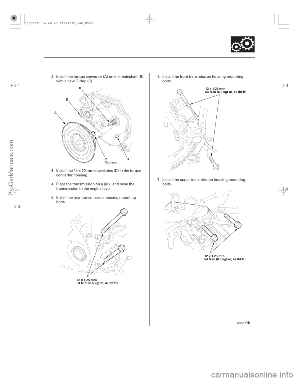
2. Install the torque converter (A) on the mainshaft (B) with a new O-ring (C).
3. Install the 14 x 20 mm dowel pins (D) in the torque converter housing.
4. Place the transmission on a jack, and raise the transmission to the engine level.
5. Install the rear transmission housing mounting bolts. 6. Install the front transmission housing mounting
bolts.
7. Install the upper transmission housing mounting bolts.
(cont’d)
Replace.
08/08/21 14:48:43 61SNR030_140_0245
ProCarManuals.com
DYNOMITE -2009-
Page 1161 of 2893
 A
6x1.0mm
12 N·m
(1.2 kgf·m, 8.7 lbf·ft)
6x1.0mm
12 N·m
(1.2 kgf·m, 8.7 lbf·ft)6x1.0mm
9.8 N·m
(1.0 kgf·m,
7.2 lbf·ft)
D
6x1.0")
�����
��
�
�
14-245
B
6x1.0mm
12 N·m
(1.2 kgf·m, 8.7 lbf·ft) A
6x1.0mm
12 N·m
(1.2 kgf·m, 8.7 lbf·ft)
6x1.0mm
12 N·m
(1.2 kgf·m, 8.7 lbf·ft)6x1.0mm
9.8 N·m
(1.0 kgf·m,
7.2 lbf·ft)
D
6x1.0mm
14 N·m
(1.4 kgf·m,
10 lbf·ft)A
B
C
E
F
VSB02C000016
A
B
C
17. Attach the torque converter to the drive plate with the eight bolts (A). Rotate the crankshaft pulley as
necessary to tighten the bolts to 1/2 of the specified
torque, then to the final torque, in a crisscross
pattern. After tightening the last bolt, check that the
crankshaft rotate freely.
18. Install the torque converter cover (B). 19. Install the control lever (A) over the selector control
shaft (B).
20. Secure the control lever with a new lock washer (C) and the lock bolt (D), then bend the lock tab of the
lock washer against the bolt head.
21. Install the shift cable cover (E), and install the shift cable holder (F) on the shift cable cover.
22. Set the front subframe adapter (VSB02C000016) to the front subframe by looping the strap (A) over the
front of the front subframe, then secure the strap
with the stop (B), then tighten the wing nut (C).
(cont’d)
08/08/21 14:48:45 61SNR030_140_0247
ProCarManuals.com
DYNOMITE -2009-
Page 1162 of 2893
�
��
�
���
��
�
��
14-246Automatic Transmission
Transmission Installation (cont’d)
14x1.5mm
103 N·m
(10.5kgf·m,75.9lbf·ft)
14x1.5mm
103 N·m
(10.5 kgf·m, 75.9 lbf·ft)
A BCC
B A 14x1.5mm
88 N·m (9.0 kgf·m, 65 lbf·ft)
C
10x1.25mm
54 N·m
(5.5 kgf·m,
40 lbf·ft) A
B
10x1.25mm
59 N·m
(6.0 kgf·m,
43 lbf·ft)
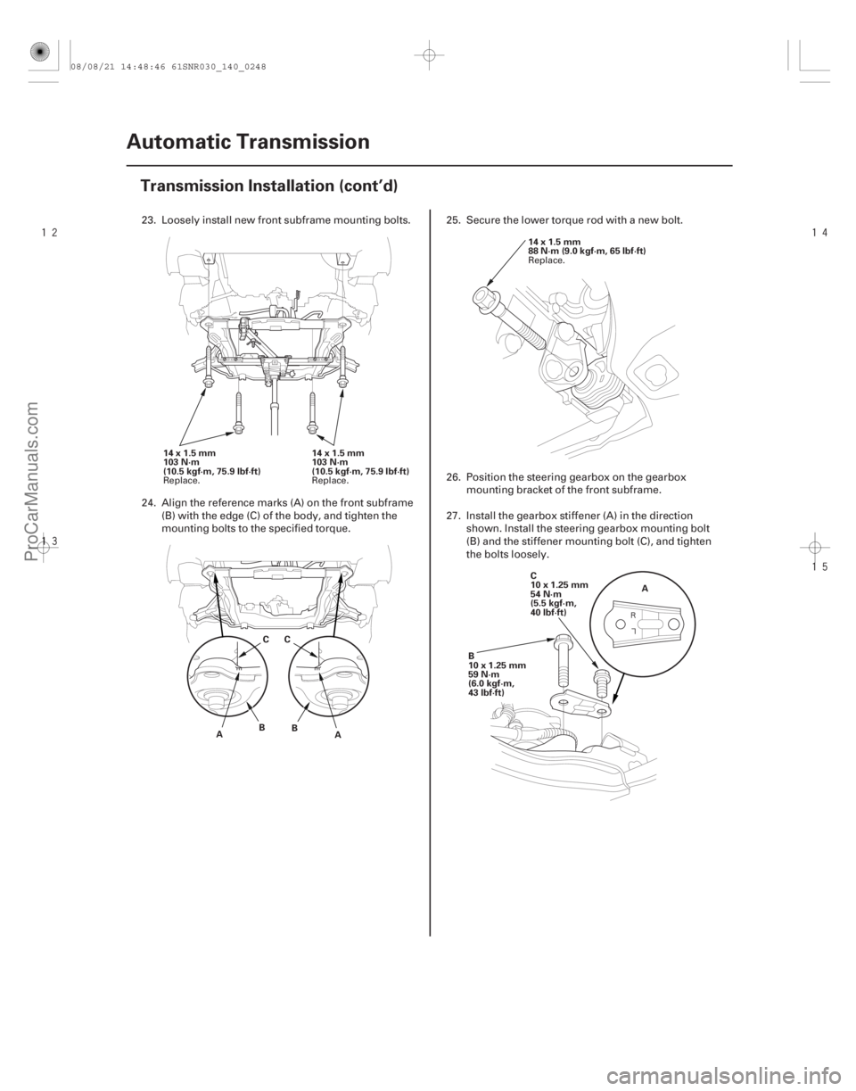
23. Loosely install new front subframe mounting bolts.
24. Align the reference marks (A) on the front subframe (B) with the edge (C) of the body, and tighten the
mounting bolts to the specified torque. 25. Secure the lower torque rod with a new bolt.
26. Position the steering gearbox on the gearbox
mounting bracket of the front subframe.
27. Install the gearbox stiffener (A) in the direction shown. Install the steering gearbox mounting bolt
(B) and the stiffener mounting bolt (C), and tighten
the bolts loosely.
Replace. Replace. Replace.
08/08/21 14:48:46 61SNR030_140_0248
ProCarManuals.com
DYNOMITE -2009-