Page 1163 of 2893
���
�����
��
����
14-247
A
C
10x1.25mm
54 N·m
(5.5 kgf·m, 40 lbf·ft)
B
10x1.25mm
59N·m(6.0kgf·m,43lbf·ft)
A
10x1.25mm
38 N·m (3.9 kgf·m, 28 lbf·ft) A6x1.0mm
9.8 N·m
(1.0 kgf·m, 7.2 lbf·ft)
12x1.25mm
64 N·m
(6.5 kgf·m, 47 lbf·ft)
12x1.25mm
64N·m(6.5kgf·m,47lbf·ft)
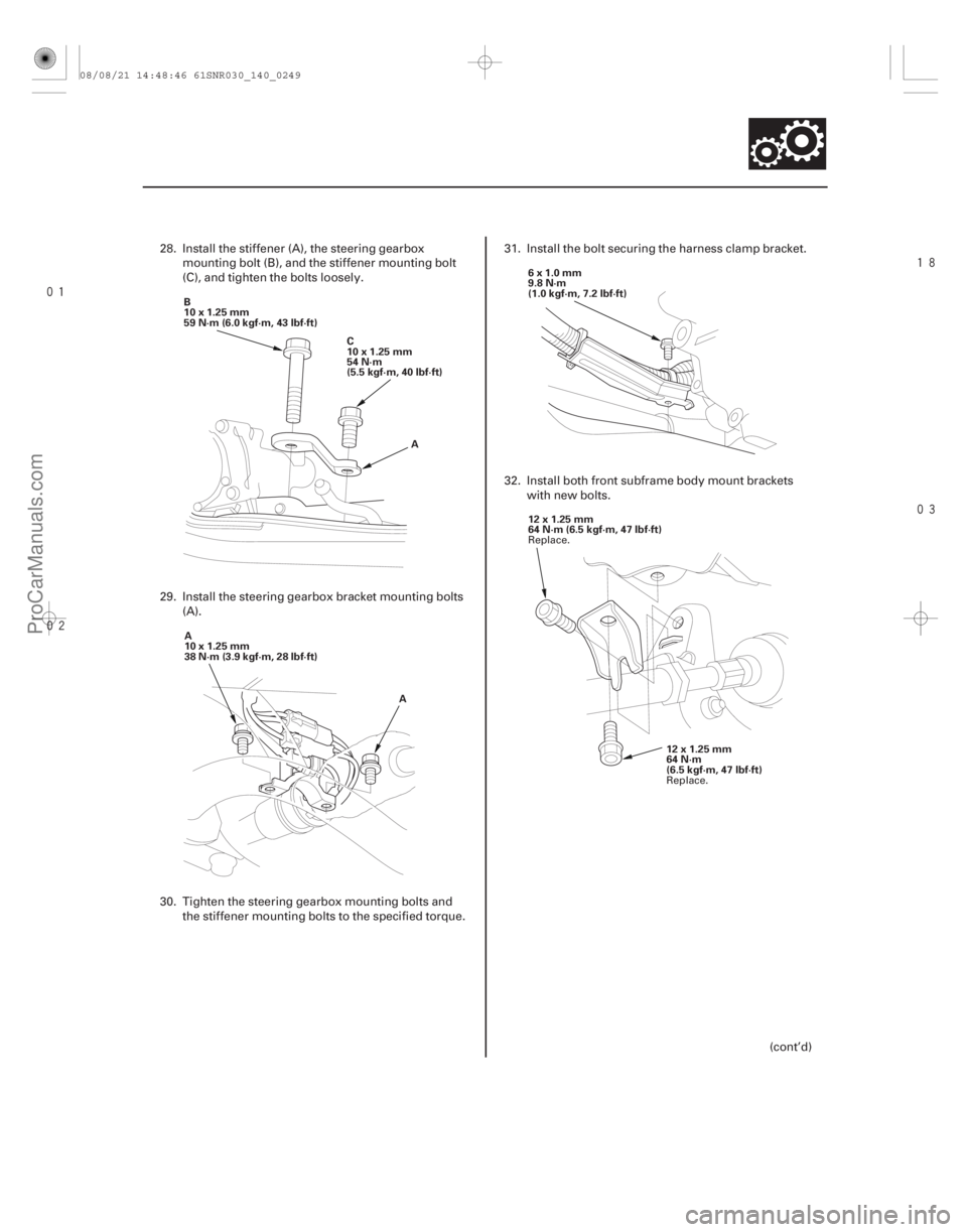
28. Install the stiffener (A), the steering gearbox
mounting bolt (B), and the stiffener mounting bolt
(C), and tighten the bolts loosely.
29. Install the steering gearbox bracket mounting bolts (A).
30. Tighten the steering gearbox mounting bolts and the stiffener mounting bolts to the specified torque. 31. Install the bolt securing the harness clamp bracket.
32. Install both front subframe body mount brackets
with new bolts.
(cont’d)
Replace.
Replace.
08/08/21 14:48:46 61SNR030_140_0249
ProCarManuals.com
DYNOMITE -2009-
Page 1167 of 2893
����
��������
14-251
A
12x1.25mm
64 N·m
(6.5 kgf·m,
47 lbf·ft)
A
12x1.25mm
74 N·m
(7.5 kgf·m, 54 lbf·ft) B
12x1.25mm
74N·m(7.5kgf·m,54lbf·ft) A
14x1.5mm
93 N·m (9.5 kgf·m, 69 lbf·ft)
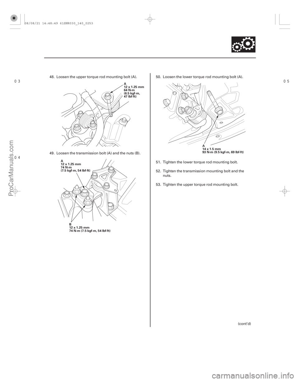
48. Loosen the upper torque rod mounting bolt (A).
49. Loosen the transmission bolt (A) and the nuts (B).
50. Loosen the lower torque rod mounting bolt (A).
51. Tighten the lower torque rod mounting bolt.
52. Tighten the transmission mounting bolt and the
nuts.
53. Tighten the upper torque rod mounting bolt.
(cont’d)
08/08/21 14:48:49 61SNR030_140_0253
ProCarManuals.com
DYNOMITE -2009-
Page 1215 of 2893

C
A
B
A
B A
BC
A
B
C
D
6. Align the spring pin (A) on the selector control shaft (B) with the transmission")
����
��������
����
14-296
Transmission Housing
Housing and Shaft Assembly Removal (cont’d)
C
A
B
A
B A
BC
A
B
C
D
6. Align the spring pin (A) on the selector control shaft (B) with the transmission housing groove (C) by
turning the selector control shaft with the control
lever.
NOTE: Do not squeeze the end of the selector
control shaft tips together when turning the shaft.
7. Use snap ring pliers to expand the snap ring of the secondary shaft bearing. Then lift the transmission
housing. Release the snap ring pliers and remove
the transmission housing.
8. Remove the countershaft r everse gear and the
needle bearing.
9. Remove the lock bolt securing the shift fork, then remove the shift fork with the reverse selector
together.
10. Remove the control lever from the selector control shaft.
11. Unlock the detent spring (A) from the detent arm (B). 12. Remove the selector control shaft (A) from the
torque converter housing.
13. Turn the detent arm (B) away from the countershaft (C).
14. Remove the mainshaft subassembly (A), the countershaft subassembly (B) and the secondary
shaft subassembly (C) together. Do not bump the
countershaft on the baffle plate (D).
15. Remove the baffle plate.
16. Remove the differential assembly.
08/08/21 14:50:16 61SNR030_140_0298
ProCarManuals.com
DYNOMITE -2009-
Page 1221 of 2893
����
14-30114-301
Valve Body Repair
B A
6. Remove the cooler check valve spring (L) and thecooler check valve (M), then remove the ma")
�����Ì
�Ì �Ì
���
�(�#�'�������
���
���������
���������
�!�����)����
14-30114-301
Valve Body Repair
B A
6. Remove the cooler check valve spring (L) and thecooler check valve (M), then remove the main valve
body (N) (three bolts). Do not let the check balls (O)
fall out.
7. Remove the ATF pump driven gear shaft (P), then remove the ATF pump gears (Q).
8. Remove the main separator plate (R) and the two dowel pins (S).
9. Remove the ATF magnet (T), clean and reinstall it in the torque converter housing (U).
10. Clean the inlet opening (A) of the ATF strainer (B) thoroughly with compressed air, then check that it
is in good condition and that the inlet opening is
not clogged.
11. Test the ATF strainer by pouring clean ATF through the inlet opening, and replace it if it is clogged or
damaged.
12. Remove the O-rings (V) (W) from the stator shaft and the ATF strainer. Install the new ones when
installing the valve bodies. NOTE: This repair is only necessary if one or more of
the valves in a valve body do not slide smoothly in their
bores. Use this procedure to free the valves.
1. Soak a sheet of 600 abrasive paper in ATF for about 30 minutes.
2. Carefully tap the valve body so the sticking valve drops out of its bore. It may be necessary to use a
small screwdriver to pry the valve free. Be careful
not to scratch the bore with the screwdriver.
3. Inspect the valve for any scuff marks. Use the ATF- soaked 600 paper to polish off any burrs that are
on the valve, then wash the valve in solvent and
dry it with compressed air.
4. Roll up half a sheet of ATF-soaked 600 paper and insert it in the valve bore of the sticking valve.
Twist the paper slightly, so that it unrolls and fits
the bore tightly, then polish the bore by twisting the
paper as you push it in and out.
NOTE: The valve body is aluminum and does not
require much polishing to remove any burrs.
(cont’d)
08/08/21 14:51:12 61SNR030_140_0303
ProCarManuals.com
DYNOMITE -2009-
Page 1222 of 2893
����
14-30114-301
Valve Body Repair
B A
6. Remove the cooler check valve spring (L) and thecooler check valve (M), then remove the ma")
�����Ì
�Ì �Ì
���
�(�#�'�������
���
���������
���������
�!�����)����
14-30114-301
Valve Body Repair
B A
6. Remove the cooler check valve spring (L) and thecooler check valve (M), then remove the main valve
body (N) (three bolts). Do not let the check balls (O)
fall out.
7. Remove the ATF pump driven gear shaft (P), then remove the ATF pump gears (Q).
8. Remove the main separator plate (R) and the two dowel pins (S).
9. Remove the ATF magnet (T), clean and reinstall it in the torque converter housing (U).
10. Clean the inlet opening (A) of the ATF strainer (B) thoroughly with compressed air, then check that it
is in good condition and that the inlet opening is
not clogged.
11. Test the ATF strainer by pouring clean ATF through the inlet opening, and replace it if it is clogged or
damaged.
12. Remove the O-rings (V) (W) from the stator shaft and the ATF strainer. Install the new ones when
installing the valve bodies. NOTE: This repair is only necessary if one or more of
the valves in a valve body do not slide smoothly in their
bores. Use this procedure to free the valves.
1. Soak a sheet of 600 abrasive paper in ATF for about 30 minutes.
2. Carefully tap the valve body so the sticking valve drops out of its bore. It may be necessary to use a
small screwdriver to pry the valve free. Be careful
not to scratch the bore with the screwdriver.
3. Inspect the valve for any scuff marks. Use the ATF- soaked 600 paper to polish off any burrs that are
on the valve, then wash the valve in solvent and
dry it with compressed air.
4. Roll up half a sheet of ATF-soaked 600 paper and insert it in the valve bore of the sticking valve.
Twist the paper slightly, so that it unrolls and fits
the bore tightly, then polish the bore by twisting the
paper as you push it in and out.
NOTE: The valve body is aluminum and does not
require much polishing to remove any burrs.
(cont’d)
08/08/21 14:51:12 61SNR030_140_0303
ProCarManuals.com
DYNOMITE -2009-
Page 1227 of 2893
���� SPRING SPECIFICATIONSSprings Standard (New)-Unit: mm (in.) Wire Diameter O.D. Free Length No. of Coils
14-305
Regulator Valve Body Disassembly")
����
�(�#�'�������
���
���������
���������
�"�����)���� SPRING SPECIFICATIONSSprings Standard (New)-Unit: mm (in.) Wire Diameter O.D. Free Length No. of Coils
14-305
Regulator Valve Body Disassembly, Inspection, and Reassembly
6x1.0mm
12 N·m (1.2 kgf·m, 8.7 lbf·ft)
F G
H 1ST ACCUMULATOR
PISTON
O-RING
REGULATOR VALVE BODY
LOCK-UP SHIFT VALVE
E
VALVE CAP CLIP
VALVE CAP REGULATOR VALVE
TORQUE CONVERTER
CHECK VALVE D
SPRING SEAT A
B
C ACCUMULATOR COVER
3RD ACCUMULATOR PISTON
REGULATOR
SPRING CAP
STOP BOLT
6x1.0mm
12 N·m (1.2 kgf·m,
8.7 lbf·ft) BAFFLE PLATE
1. Clean all parts thoroughly in solvent, and dry them with compressed air. Blow out all passages.
2. Inspect the valve body for scoring and damage.
3. Check all valves for free movement. If any fail to slide freely, do the valve body repair procedure (see page 14-301).
4. Hold the regulator spring cap in place while removing the stop bolt. The regulator spring cap is spring loaded.
5. Coat all parts with ATF during assembly.
6. Replace the O-rings with new ones.
7. When reassembling the valve body, align the hole in the regulator spring cap with the hole in the valve body, then
press the spring cap into the valve body, and tighten the stop bolt.
A Stator reaction spring 4.5 (0.177) 35.4 (1.394) 30.3 (1.193) 1.92 B Regulator valve spring A 1.9 (0.075) 14.7 (0.579) 80.6 (3.173) 16.1
C Regulator valve spring B 1.6 (0.063) 9.2 (0.362) 44.0 (1.732) 12.5
D Torque converter check valve spring 1.2 (0.047) 8.6 (0.339) 33.8 (1.331) 12.2 E Lock-up shift valve spring 1.0 (0.039) 6.6 (0.260) 35.5 (1.398) 18.2F 3rd accumulator spring 2.5 (0.098) 14.6 (0.575) 29.9 (1.177) 4.9
G 1st accumulator spring A 2.4 (0.094) 18.6 (0.732) 49.0 (1.929) 7.1 H 1st accumulator spring B 2.3 (0.091) 12.2 (0.480) 31.5 (1.240) 6.6
Replace.
08/08/21 14:51:14 61SNR030_140_0307
ProCarManuals.com
DYNOMITE -2009-
Page 1230 of 2893
����
Special Tools Required
14-308
Torque Converter Housing
Mainshaft Bearing and Oil Seal Replacement
07736-A01000B or
07736-A01000A
A")
�µ
���
���� ����
�(�#�'�������
���
�����
�
�����������
� �����)����
Special Tools Required
14-308
Torque Converter Housing
Mainshaft Bearing and Oil Seal Replacement
07736-A01000B or
07736-A01000A
A
07749-001000007746-0010500 07749-0010000
07746-0010600
Adjustable bearing puller, 25 40 mm07736-A01000B or 07736-A01000A
Driver 07749-0010000
Attachment, 62 x 68 mm 07746-0010500
Attachment, 72 x 75 mm 07746-0010600
1. Remove the mainshaft bearing and the oil seal using the adjustable bearing puller and a
commercially available 3/8 ’’-16 slide hammer (A).
2. Install a new mainshaft bearing until it bottoms in the housing using the driver and the 62 x 68 mm
attachment. 3. Install a new oil seal flush using the housing using
thedriverandthe72x75mmattachment.
NOTE: Do not drive the seal into the torque
converter housing until it bottoms out; it will block
the fluid return passage and cause transmission
damage.
08/08/21 14:51:16 61SNR030_140_0310
ProCarManuals.com
DYNOMITE -2009-
Page 1232 of 2893
����
Special Tools Required
14-310
Torque Converter Housing
Secondary Shaft Bearing Replacement
6x1.0mm
12 N·m
(1.2 kgf·m, 8.7 lbf")
���
��������
����
�(�#�'�������
���
�����
�
������������� �����)����
Special Tools Required
14-310
Torque Converter Housing
Secondary Shaft Bearing Replacement
6x1.0mm
12 N·m
(1.2 kgf·m, 8.7 lbf·ft)
A
B
B A C
B
A
07749-001000007746-0010500
Driver 07749-0010000
Attachment, 62 x 68 mm 07746-0010500 1. Remove the set plate bolt, then remove the lock washer (A) and the bearing set plate (B).
2. Remove the secondary shaft bearing (A) by heating the housing to about 100 °C (212 °F) using a heat
gun (B). Do not heat the housing more than 100 °C
(212 °F).
NOTE: Let the housing cool to normal temperature
before installing the bearing. 3. Install new O-rings (A) on the ATF guide collar (B),
then install the ATF guide collar in the housing.
4. Install new secondary shaft bearing (C) in the direction shown.
5. Install the secondary shaft bearing using the driver and the 62 x 68 mm attachment, and install it
securely in the housing.
6. Check that the bearing groove aligns with the housing surface, then install the bearing set plate
while aligning the bearing groove.
7. Install a new lock washer and the set plate bolt, then bend the lock tab of the lock washer against
the bolt head.
Replace.
08/08/21 14:51:17 61SNR030_140_0312
ProCarManuals.com
DYNOMITE -2009-