Page 2197 of 2893
����
�µ�´�µ
22-247
G5014
3 6
7
1
2
5
BLK
PUR
7
BLU 6
YEL 5
4
BRN
GRY
RED MAIN CIRCUIT
D
INDICATOR DRIVE CIRCUIT E
MAINTENANCE
MINDER
INDICATOR
(LED) SIDE
AIRBAG
CUTOFF
INDICATOR
(LED)
ILLUMI
() ILLUMI
()SEL/
RESET km/h
mph
LIGHTS
(LED)
GAUGE CONTROL
MODULE (TACH) No. 14 (7.5 A) FUSE
(UNDER-DASH
FUSE/RELAY BOX) SEAT BELT
REMINDER
INDICATOR
(LED)
SRS
INDICATOR
(LED)
DASH LIGHTS BRIGHTNESS CONTROLLER and
ODOMETER SELECT/RESET SWITCH
WASHER
FLUID LEVEL
INDICATOR
(LED)
GAUGE CONTROL MODULE (TACH)
DRL
INDICATOR
(LED)
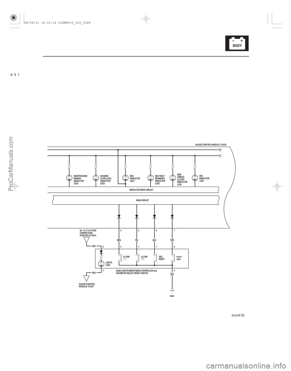
(cont’d)
08/08/21 14:35:14 61SNR030_220_0249
ProCarManuals.com
DYNOMITE -2009-
Page 2204 of 2893
�����
�µ�´�µ
22-254Gauges
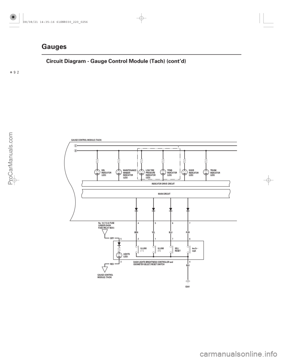
Circuit Diagram - Gauge Control Module (Tach) (cont’d)
GAUGE CONTROL MODULE (TACH)
D
MAIN CIRCUIT
INDICATOR DRIVE CIRCUIT
DRL
INDICATOR
(LED)
DOOR
INDICATOR
(LED)TRUNK
INDICATOR
(LED)
MAINTENANCE
MINDER
INDICATOR
(LED) *
LOW TIRE
PRESSURE
INDICATOR
(LED) TPMS
INDICATOR
(LED)
G5014
3 6
7
1
2
5
BLK
PUR
7
BLU 6
YEL 5
4
BRN
GRY
RED ILLUMI
()
ILLUMI
()SEL/
RESETkm/h
mph
LIGHTS
(LED)
GAUGE CONTROL
MODULE (TACH) No. 14 (7.5 A) FUSE
(UNDER-DASH
FUSE/RELAY BOX)
DASH LIGHTS BRIGHTNESS CONTROLLER and
ODOMETER SELECT/RESET SWITCH
C
08/08/21 14:35:16 61SNR030_220_0256
ProCarManuals.com
DYNOMITE -2009-
Page 2206 of 2893
����
�µ
�´
�µ
22-256 Gauges
Circuit Diagram - Dash Lights Brightness Controller
RED
GRY
BRN45
YEL 6
BLU 7
PUR
BLK
2176
4
G501 13
RED
14
16
BLK B")
����
�(�#�'���������������������
�����������������)����
�µ
�´
�µ
22-256 Gauges
Circuit Diagram - Dash Lights Brightness Controller
RED
GRY
BRN45
YEL 6
BLU 7
PUR
BLK
2176
4
G501 13
RED
14
16
BLK BLK
G503
13
RED
16
BLK BLK
G504 15
MAIN CIRCUIT
WHT BRN
No. 2 (IG) (50 A)
GAUGE CONTROL MODULE (TACH) 18 17
ORN
IG1
BAT
BLU
WHT
No. 23 (10 A)
BATTERY
IGNITION SWITCH
No. 1 (BAT) (100 A)
(7.5 A) No. 10
UNDER-DASH
FUSE/RELAY
BOX IG1 HOT in ON (II)
and START (III)
DASH LIGHTS BRIGHTNESS CONTROLLER and
ODOMETER SELECT/RESET SWITCH
No. 14 (7.5 A) FUSE
(UNDER-DASH
FUSE/RELAY BOX)
GAUGE CONTROL
MODULE (TACH) km/h
mph
SEL/
RESET
ILLUMI
()
ILLUMI
()
H1
D4 G2D2
UNDER-HOOD FUSE/RELAY BOX
5
3LIGHTS
(LED) Q1 Q9
MICU A/T GEAR POSITION INDICATOR
PANEL LIGHT
AMBIENT LIGHT
SEAT HEATER SWITCHES LIGHT
DRIVER’S FOOTWELL LIGHT*1
FRONT PASSENGER’S
FOOTWELL LIGHT*1
CLIMATE CONTROL UNIT*2
DASH LIGHTS BRIGHTNESS
CONTROLLER*2
FRONT PASSENGER’S
AIRBAG CUTOFF INDICATOR*2
VSA OFF SWITCH*2
AUDIO UNIT
NAVIGATION UNIT
HAZARD WARNING SWITCH LIGHT
MOONROOF SWITCH LIGHT
STEERING SWITCHES LIGHT
CLIMATE CONTROL UNIT*1
DASH LIGHTS BRIGHTNESS
CONTROLLER*1
FRONT PASSENGER’S
AIRBAG CUTOFF INDICATOR*1
VSA OFF SWITCH*1
*1: TYPE S model
*2: Except TYPE S model
08/08/21 14:35:17 61SNR030_220_0258
ProCarManuals.com
DYNOMITE -2009-
Page 2222 of 2893

�¦�§ �¦ �§�¦ �§
�¦�§
�¦�§
�µ
�µ
Cavity Wire Test condition
Test: Desired result Possible cause if desired result
is not obtained
Cavity Wire Test condition Test: Desired result Possible cause if desired result
is not obtained
22-272Gauges
Gauge Control Module (Tach) Input Test (cont’d)
4. With the connector still disconnected, do these input tests at the following connector.
If any test indicates a problem, find and correct the cause, then recheck the system.
If all the input tests prove OK, go to step 5.
20
2 LT GRN
GRY Disconnect the
gauge control
module (speedo)
12P connector Check for continuity between
terminal No. 20 No. 2 and
gauge control module (speedo)
12P connector terminal No. 7
No. 1 :
There should be continuity. An open in the wire
Check for continuity to ground:
There should be no continuity. A short to ground in the wire
13 RED Combination light switch ON Attach to ground:
The illuminations of the seat
heater switches and the
ambient light should come on
full bright. Faulty LEDs
An open in the wire
14 RED Combination light switch ON Attach to ground:
The illuminations of the dash
lights, the audio unit, the
steering wheel switches, and
the climate control unit lights
should come on full bright. Faulty LEDs
An open in the wire
: TYPE S model
5. Reconnect the connector to the gauge control module (tach), and do these input tests at the following connector. If any test indicates a problem, find and correct the cause, then recheck the system.
If all the input tests prove OK, the gauge control module (tach) must be faulty; replace it.
15 BLK Under all
conditions Measure the voltage to ground:
There should be less than 0.5 V. Poor ground (G503)
An open in the wire
16 BLK Under all conditions Measure the voltage to ground:
There should be less than 0.5 V. Poor ground (G504)
An open in the wire
17 BRN Ignition switch ON (II) Measure the voltage to ground:
There should be battery voltage. Blown No. 10 (7.5 A) fuse in
the under-dash fuse/relay box
An open in the wire
18 WHT Under all conditions Measure the voltage to ground:
There should be battery voltage.
An open in the wire
4 BRN Ignition switch ON (II), ILLUMI ( )
button pressed Measure the voltage to ground:
There should be less than 1 V.
Poor ground (G501)
Faulty dash light brightness
controller and odometer
select/reset switch
An open in the wire
Ignition switch ON
(II), ILLUMI ( )
button released Measure the voltage to ground:
There should be more than 5 V.
Faulty dash light brightness
controller and odometer
select/reset switch
A short to ground in the wire
Blown No. 23 (10 A) fuse in the
under-hood fuse/relay box
08/08/21 14:35:58 61SNR030_220_0274
ProCarManuals.com
DYNOMITE -2009-
Page 2223 of 2893
,")
�´
�´
Cavity Wire Test condition Test: Desired result Possible cause if desired result
is not obtained
22-273
5 YEL Ignition switch ON
(II), ILLUMI ( )
button pressed Measure the voltage to ground:
There should be less than 1 V.
Poor ground (G501)
Faulty dash light brightness
controller and odometer
select/reset switch
An open in the wire
Ignition switch ON
(II), ILLUMI ( )
button released Measure the voltage to ground:
There should be more than 5 V.
Faulty dash light brightness
controller and odometer
select/reset switch
A short to ground in the wire
6 BLU Ignition switch ON (II), SELECT/RESET
button pressed Measure the voltage to ground:
There should be less than 1 V.
Poor ground (G501)
Faulty dash light brightness
controller and odometer
select/reset switch
An open in the wire
Ignition switch ON
(II), SELECT/RESET
button released Measure the voltage to ground:
There should be more than 5 V.
Faulty dash light brightness
controller and odometer
select/reset switch
A short to ground in the wire
7 PUR Ignition switch ON (II), km/h-mph
button pressed Measure the voltage to ground:
There should be less than 1 V.
Poor ground (G501)
Faulty dash light brightness
controller and odometer
select/reset switch
An open in the wire
Ignition switch ON
(II), km/h-mph
button released Measure the voltage to ground:
There should be more than 5 V.
Faulty dash light brightness
controller and odometer
select/reset switch
A short to ground in the wire
8 BLU Ignition switch ON (II), washer fluid is
half or more in the
washer reservoir Measure the voltage to ground:
There should be more than 5 V.
Faulty washer fluid level
switch
A short to ground in the wire
Ignition switch ON
(II), washer fluid is
empty in the
washer reservoir Measure the voltage to ground:
There should be less than 1 V.
Poor ground (G401)
Faulty washer fluid level
switch
An open in the wire
27 GRN Ignition switch ON (II), brake fluid is
full level in the
reservoir Measure the voltage to ground:
There should be less than 1 V.
Poor ground (G401)
Faulty brake fluid level switch
An open in the wire
Ignition switch ON
(II), brake fluid is
lower level in the
reservoir Measure the voltage to ground:
There should be more than 5 V.
Faulty brake fluid level switch
A short to ground in the wire
28 LT GRNIgnition switch ON
(II), parking brake
lever pulled Measure the voltage to ground:
There should be less than 1 V.
Faulty parking brake switch
An open in the wire
Ignition switch ON
(II), parking brake
lever released Measure the voltage to ground:
There should be more than 5 V.
Faulty parking brake switch
A short to ground in the wire
08/08/21 14:35:58 61SNR030_220_0275
ProCarManuals.com
DYNOMITE -2009-
Page 2228 of 2893
���
����
�(�#�'���������������������
�
�������
�������)����
�´
�µ
22-278Gauges
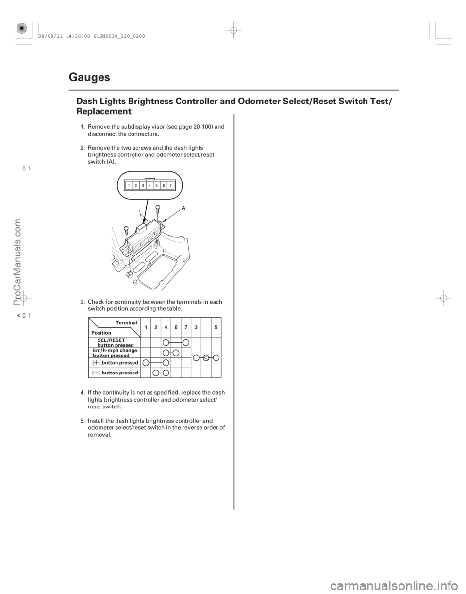
Dash Lights Brightness Controller and Odometer Select/Reset Switch Test/
Replacement
A
Terminal
Position SEL/RESET
button pressed
( ) button pressed km/h-mph change
button pressed
( ) button pressed 12
467
35
1. Remove the subdisplay visor (see page 20-
100) and
disconnect the connectors.
2. Remove the two screws and the dash lights brightness controller and odometer select/reset
switch (A).
3. Check for continuity between the terminals in each switch position according the table.
4. If the continuity is not as specified, replace the dash lights brightness controller and odometer select/
reset switch.
5. Install the dash lights brightness controller and odometer select/reset switch in the r everse order of
removal.
08/08/21 14:36:00 61SNR030_220_0280
ProCarManuals.com
DYNOMITE -2009-
Page 2230 of 2893

Desired correction value = 1 °C ( 2 °F)
Correct value = 21 °C (70 °F)
Desired correction valu")
�¶�¶�´�µ
�´�µ
�¶
���
����
�´�´
�µ�µ
Calibration
Example:
Incorrect value = 20 °C (68 °F)
Desired correction value = 1 °C ( 2 °F)
Correct value = 21 °C (70 °F)
Desired correction value = 1 °C ( 2 °F)
Correct value = 19 °C (66 °F)
22-280 Gauges
Outside Air Temperature Indicator Calibration (cont’d)
B
A
C
The outside air temperature indicator’s displayed
temperature can be recalibrated 3 °C (or 5 °F) to
meet the client’s expectations. 1. Turn the ignition switch to ON (II).
2. Select the outside air temperature display.
3. Press and hold the SEL/RESET button until the trip meter resets, then release it. Press, and continue to
hold, the switch again, and the display will scroll
through temperature settings from 3 °C to 3 °C
(or 5 °F to 5 °F) as shown.
4. When the desired correction value appears on the display, release the button, and the recalibrated
outside air temperature will be displayed.
NOTE: To recalibration temperature is not the value
the sensor sees. Therefore the temperature can
only be adjusted degrees from the sensor. NOTE: To recalibrate the display to the true
temperature, remove the outside air temperature
sensor (A), but leave it connected. Submerge the sensor
and a thermometer (B) in a container of ice water (C).
Select the calibration mode as described above, then
recalibrate the display to the true temperature.
08/08/21 14:36:00 61SNR030_220_0282
ProCarManuals.com
DYNOMITE -2009-
Page 2236 of 2893
������(�#�'���������������������������������������)����
22-286Moonroof
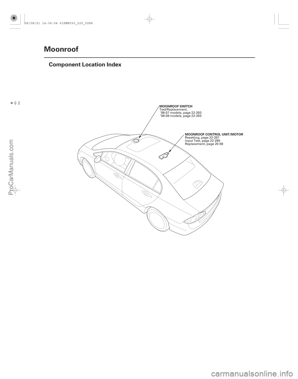
Component Location Index
MOONROOF CONTROL UNIT/MOTOR
MOONROOF SWITCH
Resetting, page 22-287
Input Test, page 22-290
Replacement, page 20-59
Test/Replacement,
’06-07 models, page 22-293
’08-09 models, page 22-293
08/08/21 14:36:04 61SNR030_220_0288
ProCarManuals.com
DYNOMITE -2009-