���
�(�#�'���������������������������������������)����
General PrecautionsSteering-related Precautions
Cable Reel Alignment
24-13
Precautions and Procedures
NOTE: Some systems store data in memory that is lost
when the battery is disconnected. Before disconnecting
the battery, refer to Battery Terminal Disconnection and
Reconnection (see page 22-68).
Please read the following precautions carefully before
servicing the airbag system. If the instructions
described in this manual are not properly followed, or
the airbags could accidentally deploy and cause
damage or injuries. Except when doing electrical inspections, always turn the ignition switch to LOCK (0), disconnect the
negative cable from the battery, then wait at least
3 minutes before starting work.
NOTE: The SRS memory is not cleared even if the
ignition switch is turned to LOCK (0), or the battery
cables are disconnected from the battery.
Use replacement parts which are manufactured to the same standards and quality as the original parts. Do
not install used SRS parts. Use only new parts when
making SRS repairs.
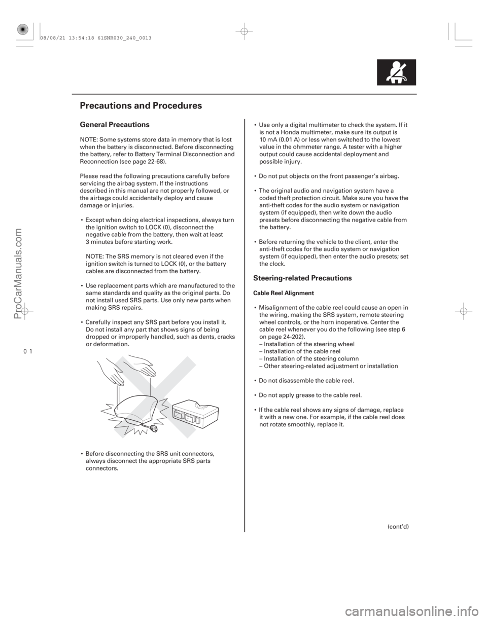
Carefully inspect any SRS part before you install it. Do not install any part that shows signs of being
dropped or improperly handled, such as dents, cracks
or deformation.
Before disconnecting the SRS unit connectors, always disconnect the appropriate SRS parts
connectors. Use only a digital multimeter to check the system. If it
is not a Honda multimeter, make sure its output is
10 mA (0.01 A) or less when switched to the lowest
value in the ohmmeter range. A tester with a higher
output could cause accidental deployment and
possible injury.
Do not put objects on the front passenger’s airbag.
The original audio and navigation system have a coded theft protection circuit. Make sure you have the
anti-theft codes for the audio system or navigation
system (if equipped), then write down the audio
presets before disconnecting the negative cable from
the battery.
Before returning the vehicle to the client, enter the anti-theft codes for the audio system or navigation
system (if equipped), then enter the audio presets; set
the clock.
Misalignment of the cable reel could cause an open in the wiring, making the SRS system, remote steering
wheel controls, or the horn inoperative. Center the
cable reel whenever you do the following (see step 6
on page 24-202).
– Installation of the steering wheel
– Installation of the cable reel
– Installation of the steering column
– Other steering-related adjustment or installation
Do not disassemble the cable reel.
Do not apply grease to the cable reel.
If the cable reel shows any signs of damage, replace it with a new one. For example, if the cable reel does
not rotate smoothly, replace it.
(cont’d)
08/08/21 13:54:18 61SNR030_240_0013
ProCarManuals.com
DYNOMITE -2009-
���
�(�#�'��������� �����
�����������������������)����
DTC (Diagnostic Trouble Codes) Reading the DTC
Precautions
24-22SRS
General Troubleshooting Information
A
The self-diagnostic function of the SRS system allows it
to locate the causes of system problems and store this
information in memory. For easier troubleshooting, this
data can be retrieved via a data link circuit.
When you turn the ignition switch to ON (II), the SRS indicator comes on. If it goes off after 6 seconds, the
system is normal, and is not currently detecting any
abnormality.
If there is an abnormality, the system locates and defines the problem, stores this information in
memory, and turns on the SRS indicator. The data
remains in memory even if the ignition switch is
turned off or the battery is disconnected.
The data is stored in memory as a diagnostic trouble code (DTC).
The ‘‘x’’ at the end of each DTC denotes a numeric character (0 thru 9) or an alpha character (A thru F)
that is displayed on the HDS.
DTCs are either latching or resetting depending on the malfunction. With resetting DTCs, the SRS
indicator goes off the next time the ignition switch is
turned to ON (II), and the system is normal, but the
DTC is still stored. With latching DTCs, the SRS
indicator does not turn to LOCK (0) until the
malfunction is repaired and the DTC is cleared.
When you connect the HDS to the data link connector (DLC), you can retrieve a more detailed DTC in the
HDS ‘‘SRS’’ menu.
NOTE: Only read DTCs from the SRS menu, not from
the SWS menus. SWS (ODS unit) DTCs are subcodes
of SRS unit DTCs. Only troubleshoot the
corresponding SRS DTCs.
After reading and recording the DTC, proceed with the troubleshooting procedure for that code.
Use only a digital multimeter to check the system. Make sure its output is 10 mA (0.01 A) or less when
switched to the smallest value in the ohmmeter range.
A tester with a higher output could damage the
airbag circuit or cause accidental airbag deployment
and possible injury. Whenever the ignition switch is in ON (II), or has been
turned to LOCK (0), for less than 3 minutes, be careful
not to bump the SRS unit; the airbags could
accidentally deploy and cause damage or injuries.
Before removing the dashboard wire harness, floor wire harness, disconnect the driver’s airbag
connector, the front passenger’s airbag connector,
both side airbag connectors, both side curtain airbag
connectors and both seat belt tensioner connectors.
Make sure the battery is fully charged. If the battery is dead or low, electrical measurements may not be
correct.
Do not touch a tester probe to the terminals in the SRS unit or harness connectors, and do not connect
the SRS unit terminals or the sensor terminals with a
jumper wire. Use only the backprobe set and the
multimeter. Backprobe spring-loaded lock type
connectors correctly.
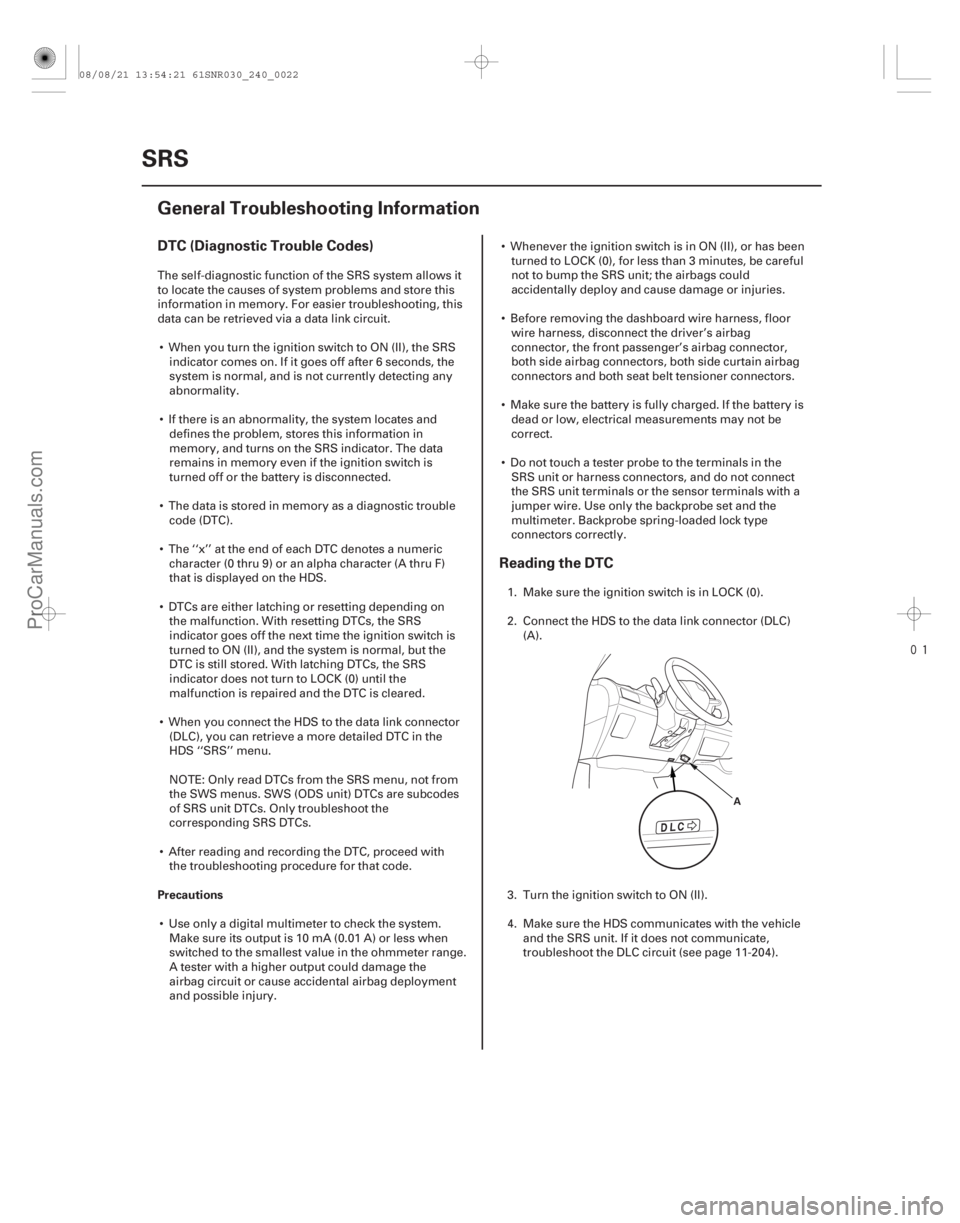
1. Make sure the ignition switch is in LOCK (0).
2. Connect the HDS to the data link connector (DLC) (A).
3. Turn the ignition switch to ON (II).
4. Make sure the HDS communicates with the vehicle and the SRS unit. If it does not communicate,
troubleshoot the DLC circuit (see page 11-204).
08/08/21 13:54:21 61SNR030_240_0022
ProCarManuals.com
DYNOMITE -2009-