Page 213 of 2893

B
A A
B
19. Connect the positive crankcase ventilation (PCV)hose (A) (K20Z2 engine) and install the ground
cable (B).
20. Connect the fu")
�
��
�����
��
6-65
A
B6x1.0mm
12 N·m
(1.2 kgf·m, 8.7 lbf·ft)
B
A A
B
19. Connect the positive crankcase ventilation (PCV)hose (A) (K20Z2 engine) and install the ground
cable (B).
20. Connect the fuel feed hose (A) (see page 11-331), then install the quick-connect fitting cover (B). 21. Connect the evaporative emission (EVAP) canister
hose (A) and the brake booster vacuum hose (B).
22. Install the exhaust manifold (see page 9-11).
23. Install the intake manifold: K20Z2 engine (see page 9-4)
K20Z3 engine (see page 9-9)
24. Install the drive belt (see page 4-31).
25. Install the air cleaner assembly (see page 11-345).
26. After installation, check that all tubes, hoses and connectors are installed correctly.
27. Inspect for fuel leaks. Turn the ignition switch to ON (II) (do not operate the starter) so that the fuel
pump runs for about 2 seconds and pressurizes the
fuel line. Repeat this operation three times, then
check for fuel leakage at any point in the fuel line.
(cont’d)
08/08/21 14:28:44 61SNR030_060_0065
ProCarManuals.com
DYNOMITE -2009-
Page 265 of 2893
���
�(�#�'�������������������������������
�"�����)���
K20Z3 engine
Torque: 16 N·m (1.6 kgf·m, 12 lbf·ft)
8-14Engine Lubrication
Oil Jet Inspection
1.2 mm (0.05 in.)
1.2 mm
(0.05 in.)
A
B
1. Remove the oil jet, and inspect it as follows. Make sure that a 1.1 mm (0.04 in.) diameter drillwill go through the nozzle hole (A) (1.2 mm
(0.05 in.) diameter).
Insert the other end of a 1.1 mm (0.04 in.) drill into the oil intake (1.2 mm (0.05 in.) diameter).
Make sure the check ball (B) moves smoothly and
has a stroke of approximately 4.0 mm (0.16 in.).
Check the oil jet operation with an air nozzle. It should take at least 200 kPa (2.0 kgf/cm , 28 psi)
to unseat the check ball.
NOTE: Replace the oil jet assembly if the nozzle is
damaged or bent.
2. Carefully install the oil jet. The mounting torque is critical.
2
08/08/21 14:36:45 61SNR030_080_0014
ProCarManuals.com
DYNOMITE -2009-
Page 277 of 2893
����
Exploded View - K20Z2 engine
9-2Intake Manifold and Exhaust System
Intake Manifold Removal and Installation
INTAKE AIR BYPASS (IAB)
THERMAL VALVE")
���
�(�#�'�������������������������������
� �����)����
Exploded View - K20Z2 engine
9-2Intake Manifold and Exhaust System
Intake Manifold Removal and Installation
INTAKE AIR BYPASS (IAB)
THERMAL VALVE
JOINT GASKET
THROTTLE BODY
INTAKE MANIFOLD BRACKET
MANIFOLD
ABSOLUTE
PRESSURE
(MAP)
SENSOR INJECTOR BASE
EXHAUST GAS
PRECIRCULATION
(EGR) PLATE 6x1.0mm
12 N·m
(1.2 kgf·m, 8.7 lbf·ft)
8 x 1.25 mm
22 N·m
(2.2 kgf·m, 16 lbf·ft) 8 x 1.25 mm
22 N·m
(2.2 kgf·m,
16 lbf·ft)
GASKET
INTAKE MANIFOLD
O-RING
5x0.8mm
3.4 N·m
(0.35 kgf·m, 2.5 lbf·ft)
8x1.25mm
22 N·m
(2.2 kgf·m, 16 lbf·ft)
GASKET
8x1.25mm
22 N·m
(2.2 kgf·m, 16 lbf·ft)
GASKET
6x1.0mm
12 N·m
(1.2 kgf·m, 8.7 lbf·ft) 6x1.0mm
12 N·m
(1.2 kgf·m,
8.7 lbf·ft)
INTAKE MANIFOLD
CHAMBER
8 x 1.25 mm
22 N·m
(2.2 kgf·m, 16 lbf·ft)
GASKET
MARK
Tigten the valve to 15 N·m
(1.5 kgf·m, 11 lbf·ft), then turn the
valve joint toward the mark.
Replace.
Replace if cracked or
if mating surface is
damaged.
Replace.
Replace if cracked or
if mating surface is
damaged.
Replace.
Replace.
Replace.
Replace.
08/08/21 14:37:29 61SNR030_090_0002
ProCarManuals.com
DYNOMITE -2009-
Page 278 of 2893
����
��������
����
Removal - K20Z2 engine
9-3
A
B C A
B
C D
A
1. Remove the engine cover.
2. Disconnect the vacuum hose (A) and the breatherpipe (B), then remove the intake air duct (C). 3. Disconnect the engine wire harness connectors,
and remove the wire harness clamps from the
intake manifold:
Manifold absolute pressure (MAP) sensor connector
Throttle actuator connector
4. Disconnect the evaporative emission (EVAP) canister hose (A) and the brake booster vacuum
hose (B).
5. Remove the harness bracket mounting bolt (C) and the brake booster vacuum line bracket mounting
bolt (D).
6. Disconnect the water bypass hoses (A), then plug the water bypass hoses.
(cont’d)
08/08/21 14:37:30 61SNR030_090_0003
ProCarManuals.com
DYNOMITE -2009-
Page 280 of 2893
 D
6x1.0mm
12 N·m (1.2 kgf·m, 8.7 lbf·ft)
B
C A
6x1.0mm
12 N·m
(1.2 kgf·m, 8.7 lbf·ft)
6. Connect the water bypass hose")
������
�
�
��
�
��
9-5
A
A
B
C
6x1.0mm
12 N·m (1.2 kgf·m, 8.7 lbf·ft) D
6x1.0mm
12 N·m (1.2 kgf·m, 8.7 lbf·ft)
B
C A
6x1.0mm
12 N·m
(1.2 kgf·m, 8.7 lbf·ft)
6. Connect the water bypass hoses (A).
7. Connect the evaporative emission (EVAP) canister hose (A) and the brake booster vacuum hose (B).
8. Install the harness bracket mounting bolt (C) and the brake booster vacuum line bracket mounting
bolt (D).
9. Connect the engine wire harness connectors, and install the wire harness clamps to the intake
manifold.
Manifold absolute pressure (MAP) sensor connector
Throttle actuator connector 10. Install the intake air duct (A), then connect the
vacuum hose (B) and the breather pipe (C).
11. Install the engine cover.
12. After installation, check that all tubes, hoses and connectors are installed correctly.
13. Clean up any spilled engine coolant.
14. Refill the radiator with engine coolant, and bleed the air from the cooling system with the heater
valve open (see step 6 on page 10-8).
08/08/21 14:37:32 61SNR030_090_0005
ProCarManuals.com
DYNOMITE -2009-
Page 281 of 2893
���
�(�#�'�������������������������������
� �����)���
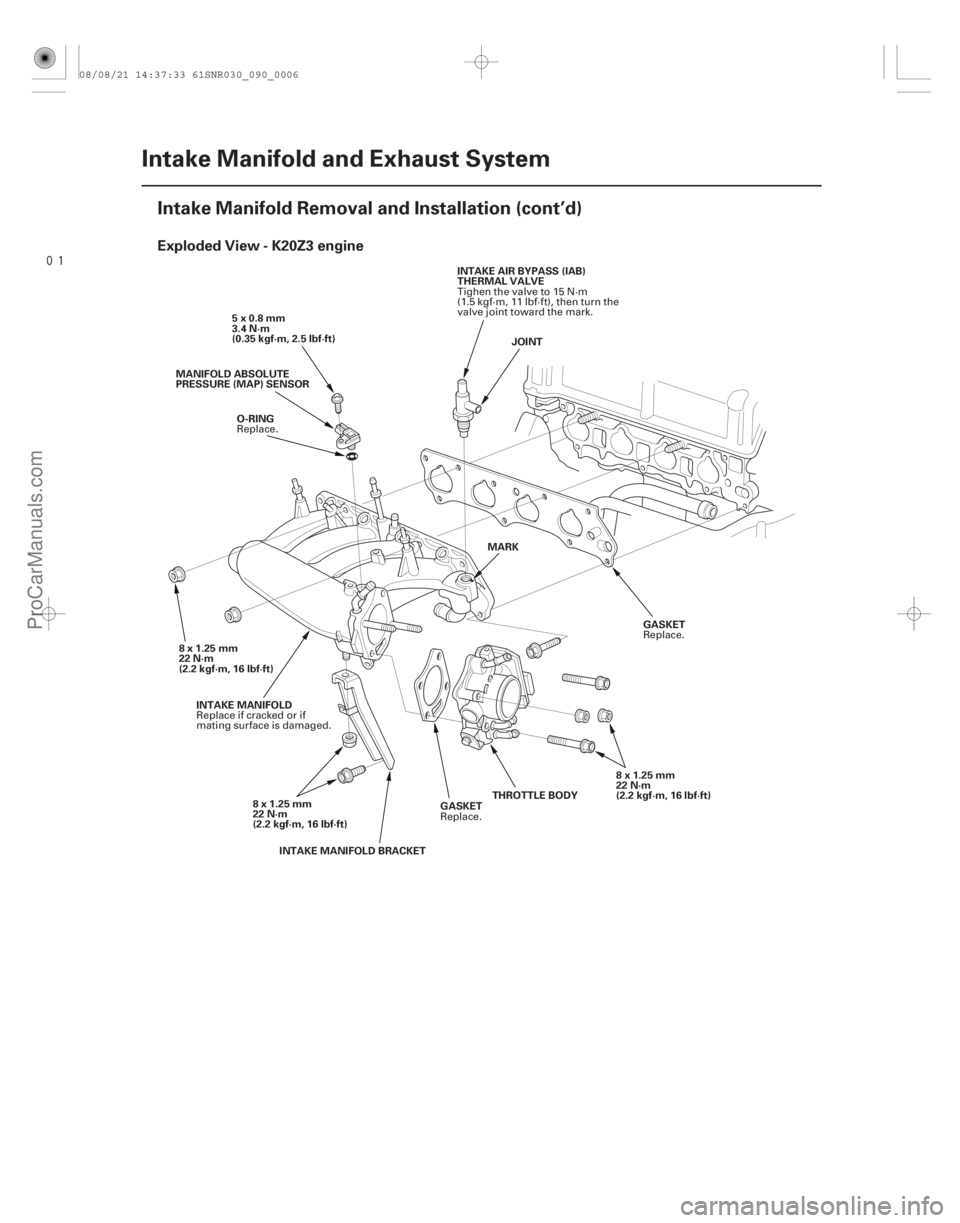
Exploded View - K20Z3 engine
9-6Intake Manifold and Exhaust System
Intake Manifold Removal and Installation (cont’d)
JOINT
GASKET
5x0.8mm
3.4 N·m
(0.35 kgf·m, 2.5 lbf·ft)
8 x 1.25 mm
22 N·m
(2.2 kgf·m, 16 lbf·ft) GASKET
O-RING
MANIFOLD ABSOLUTE
PRESSURE (MAP) SENSOR
INTAKE MANIFOLD BRACKET
INTAKE MANIFOLD
THROTTLE BODY
8x1.25mm
22 N·m
(2.2 kgf·m, 16 lbf·ft) 8x1.25mm
22 N·m
(2.2 kgf·m, 16 lbf·ft)
MARK
INTAKE AIR BYPASS (IAB)
THERMAL VALVE
Replace.
Replace.
Replace.
Replace if cracked or if
mating surface is damaged. Tighen the valve to 15 N·m
(1.5 kgf·m, 11 lbf·ft), then turn the
valve joint toward the mark.
08/08/21 14:37:33 61SNR030_090_0006
ProCarManuals.com
DYNOMITE -2009-
Page 282 of 2893
����
��������
����
Removal - K20Z3 engine
9-7
A
B C A
B
C
A B
C
1. Remove the engine cover.
2. Relieve the fuel pressure (see page 11-322).
3. Disconnect the vacuum hose (A) and the breather
pipe (B), then remove the intake air duct (C). 4. Disconnect the following engine wire harness
connectors, and remove the wire harness clamps
from the intake manifold:
Four fuel injector connectors
Manifold absolute pressure (MAP) sensor connector
Throttle actuator connector
5. Remove the ground cable (A) and the harness clamp bracket (B), then remove the harness holder
(C) from the bracket.
6. Disconnect the positive crankcase ventilation (PCV) hose (A), the evaporative emission (EVAP) canister
hose (B) and the brake booster vacuum hose (C).
(cont’d)
08/08/21 14:37:34 61SNR030_090_0007
ProCarManuals.com
DYNOMITE -2009-
Page 285 of 2893

A
B
C
B
C
A 6x1.0mm
12 N·m (1.2 kgf·m, 8.7 lbf·ft) B
C A
6x1.0mm
12 N·m (1")
�����
����������
�����
9-10Intake Manifold and Exhaust System
Intake Manifold Removal and Installation (cont’d)
A
B
C
B
C
A 6x1.0mm
12 N·m (1.2 kgf·m, 8.7 lbf·ft) B
C A
6x1.0mm
12 N·m (1.2 kgf·m, 8.7 lbf·ft)
8. Connect the positive crankcase ventilation (PCV) hose (A), the evaporative emission (EVAP) canister
hose (B) and the brake booster vacuum hose (C).
9. Install the harness holder (A) to the bracket, then install the ground cable (B) and the harness clamp
bracket (C).
10. Connect the engine wire harness connectors, and install the wire harness clamps to the intake
manifold:
Four fuel injector connectors
Manifold absolute pressure (MAP) sensor connector
Throttle actuator connector 11. Install the intake air duct (A), then connect the
vacuum hose (B) and breather pipe (C).
12. Install the engine cover.
13. Inspect for fuel leaks. Turn the ignition switch to ON (II) (do not operate the starter) so the fuel pump
runs for about 2 seconds and pressurizes the fuel
line. Repeat this operation three times, then check
for fuel leakage at any point in the fuel line.
14. Clean up any spilled engine coolant.
15. After installation, check that all tubes, hoses and connectors are installed correctly.
16. Refill the radiator with engine coolant, and bleed the air from the cooling system with the heater
valve open (see step 6 on page 10-8).
08/08/21 14:37:36 61SNR030_090_0010
ProCarManuals.com
DYNOMITE -2009-