�����
21-101
80 %HUMIDITY
LEVEL
°C
(°F)
49
(120)
psi
(kPa)
350
(2413)
275
(1896)
175
(1207)
HIGH SIDE
(DISCHARGE)
PRESSURE
35
(95)
Ambient (Intake) Temperature vs. High Side (Discharge) Pressure
AMBIENT (INTAKE) TEMPERATURE 30 %
300
(2068)
200
(1379)
125
(862) 325
(2241)
250
(1724)
225
(1551)
150
(1034)
100
(689)
75
(517) 0 46
(115)
43
(110)
41
(105)
38
(100)
32
(90)
29
(85)
27
(80)
24
(75)
21
(70)
18
(65)
16
(60)
11. To complete the high side (discharge pressure)/ambient air (intake) temperature chart:
Mark the high side (discharge pressure) temperature on the vertical line.
Mark the ambient air (intake) temperature on the bottom line.
Draw a vertical line from the high side (discharge pressure) temperature mark.
Draw a horizontal line from the vent (delivery) temperature mark unit it intersects the vertical line.NOTE: The low side and intake temperatures should intersect in the shaded area within about 10 % of the
measured humidity level. Any measurements outside the line may indicate the need for further inspection.
(cont’d)
08/08/21 14:44:56 61SNR030_210_0102
ProCarManuals.com
DYNOMITE -2009-
�����
21-102Climate Control
A/C System Test (cont’d)
80 %
HUMIDITY
LEVEL
°C
(°F)
49
(120)
psi
(kPa)
60
(414)
45
(310)
25
(172)
LOW SIDE
(SUCTION)
PRESSURE
35
(95)
Ambient (Intake) Temperature vs. Low Side (Suction) Pressure
AMBIENT (INTAKE) TEMPERATURE 30 %
50
(345)
30
(207)
15
(103) 55
(379)
40
(276) 35
(241)
20
(138)
10
(69) 5
(34)0 46
(115)
43
(110)
41
(105)
38
(100)
32
(90)
29
(85)
27
(80)
24
(75)
21
(70)
18
(65)
16
(60)
12. To complete the low side (suction pressure)/ambient air (intake) temperature chart:
Mark the low side (suction pressure) temperature along the vertical line.
Mark the ambient air (intake) temperature along the bottom line.
Draw a vertical line from the ambient air (intake) temperature mark.
Draw a horizontal line from the vent (delivery) temperature mark unit it intersects the vertical line.NOTE: The low side and intake temperatures should intersect in the shaded area within about 10 % of the
measured humidity level. Any measurements outside the line may indicate the need for further inspection.
08/08/21 14:44:56 61SNR030_210_0103
ProCarManuals.com
DYNOMITE -2009-
���
����
�(�#�'���������������������������
����� �����)����
Removal Installation
24-210SRS
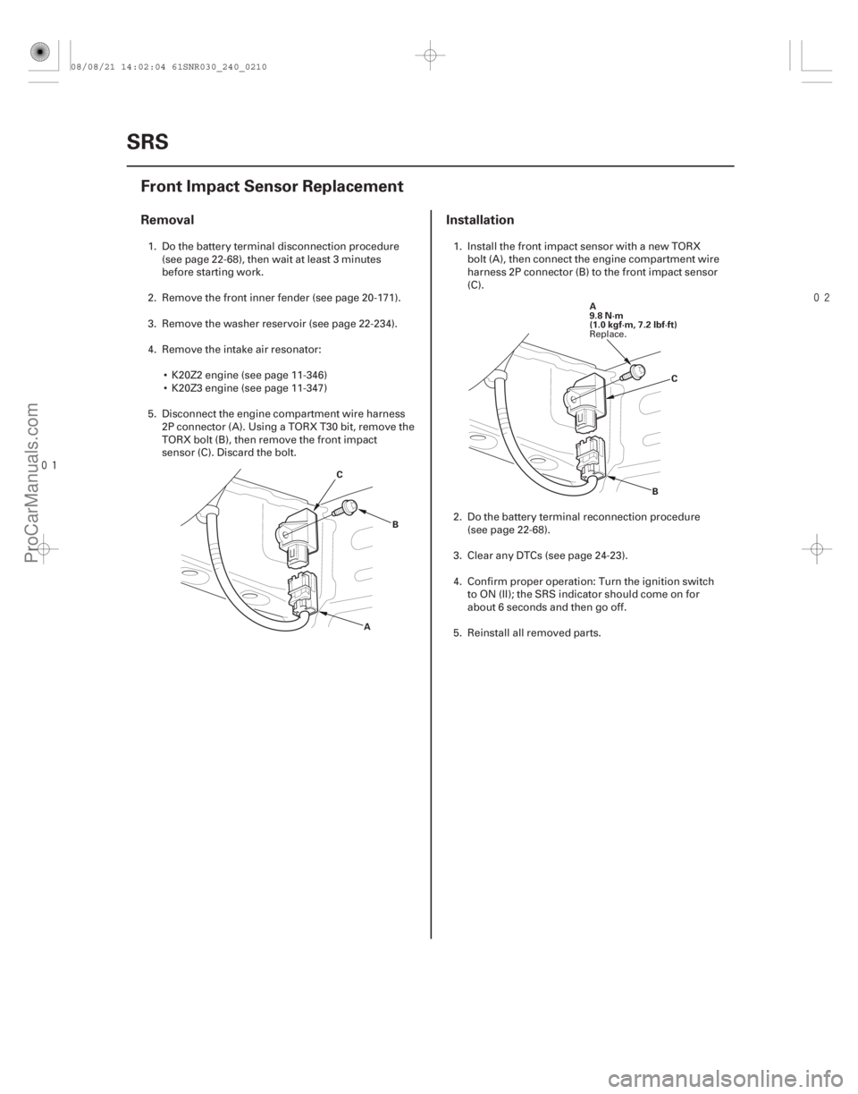
Front Impact Sensor Replacement
A
B
C A
9.8 N·m
(1.0 kgf·m, 7.2 lbf·ft)
C
B
1. Do the battery terminal disconnection procedure (see page 22-68), then wait at least 3 minutes
before starting work.
2. Remove the front inner fender (see page 20-171).
3. Remove the washer reservoir (see page 22-234).
4. Remove the intake air resonator: K20Z2 engine (see page 11-346)
K20Z3 engine (see page 11-347)
5. Disconnect the engine compartment wire harness 2P connector (A). Using a TORX T30 bit, remove the
TORX bolt (B), then remove the front impact
sensor (C). Discard the bolt. 1. Install the front impact sensor with a new TORX
bolt (A), then connect the engine compartment wire
harness 2P connector (B) to the front impact sensor
(C).
2. Do the battery terminal reconnection procedure (see page 22-68).
3. Clear any DTCs (see page 24-23).
4. Confirm proper operation: Turn the ignition switch to ON (II); the SRS indicator should come on for
about 6 seconds and then go off.
5. Reinstall all removed parts.
Replace.
08/08/21 14:02:04 61SNR030_240_0210
ProCarManuals.com
DYNOMITE -2009-