Page 1460 of 2893
����
�(�#�'���������������
�����
�����������������)����
18-48TPMS
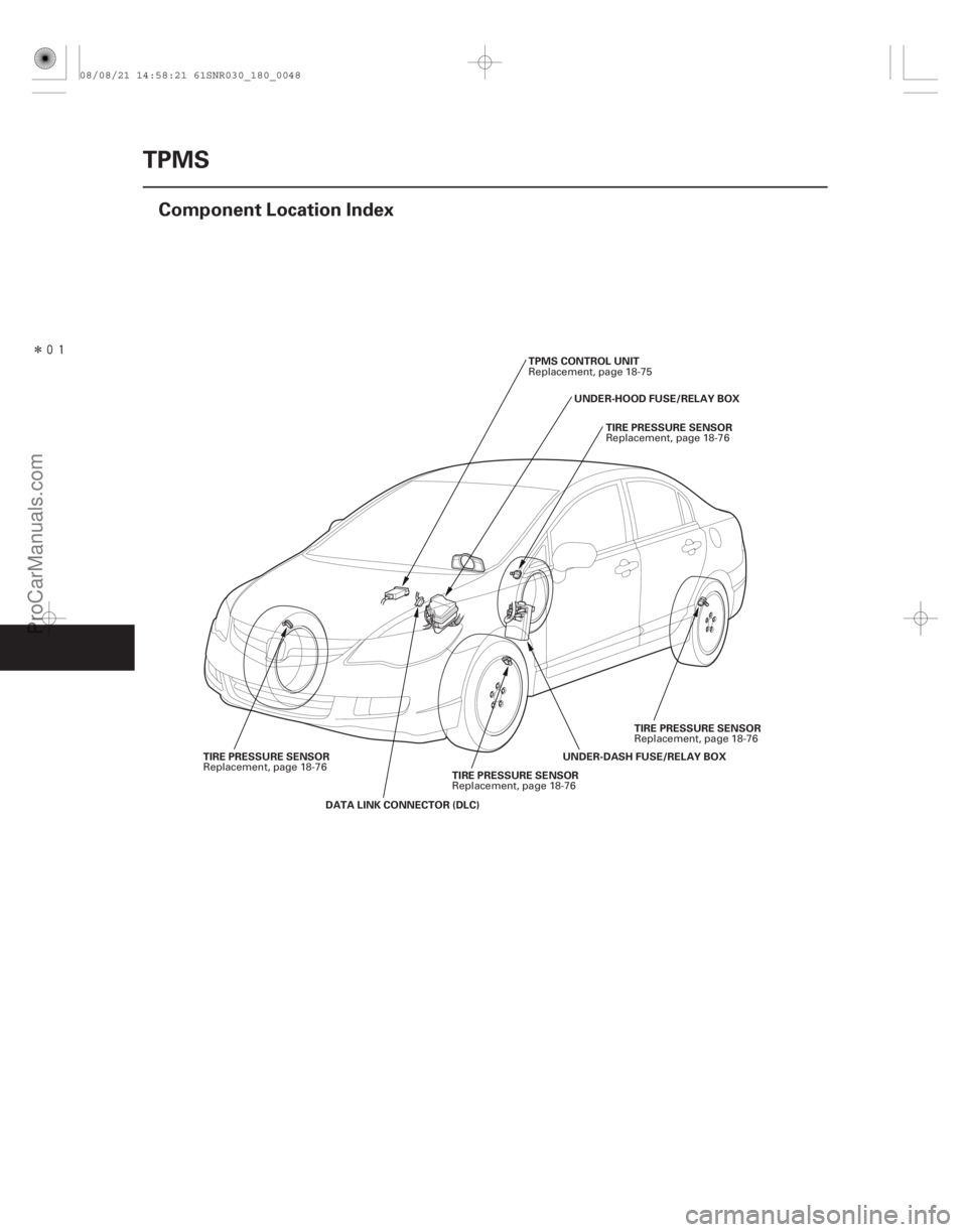
Component Location Index
TIRE PRESSURE SENSOR
DATA LINK CONNECTOR (DLC) UNDER-DASH FUSE/RELAY BOX
TPMS CONTROL UNIT
TIRE PRESSURE SENSOR
TIRE PRESSURE SENSOR
TIRE PRESSURE SENSOR UNDER-HOOD FUSE/RELAY BOX
Replacement, page 18-76 Replacement, page 18-75
Replacement, page 18-76
Replacement, page 18-76
Replacement, page 18-76
08/08/21 14:58:21 61SNR030_180_0048
ProCarManuals.com
DYNOMITE -2009-
Page 1474 of 2893
���
�(�#�'���������������
�����
�����������������)����
�´
18-61
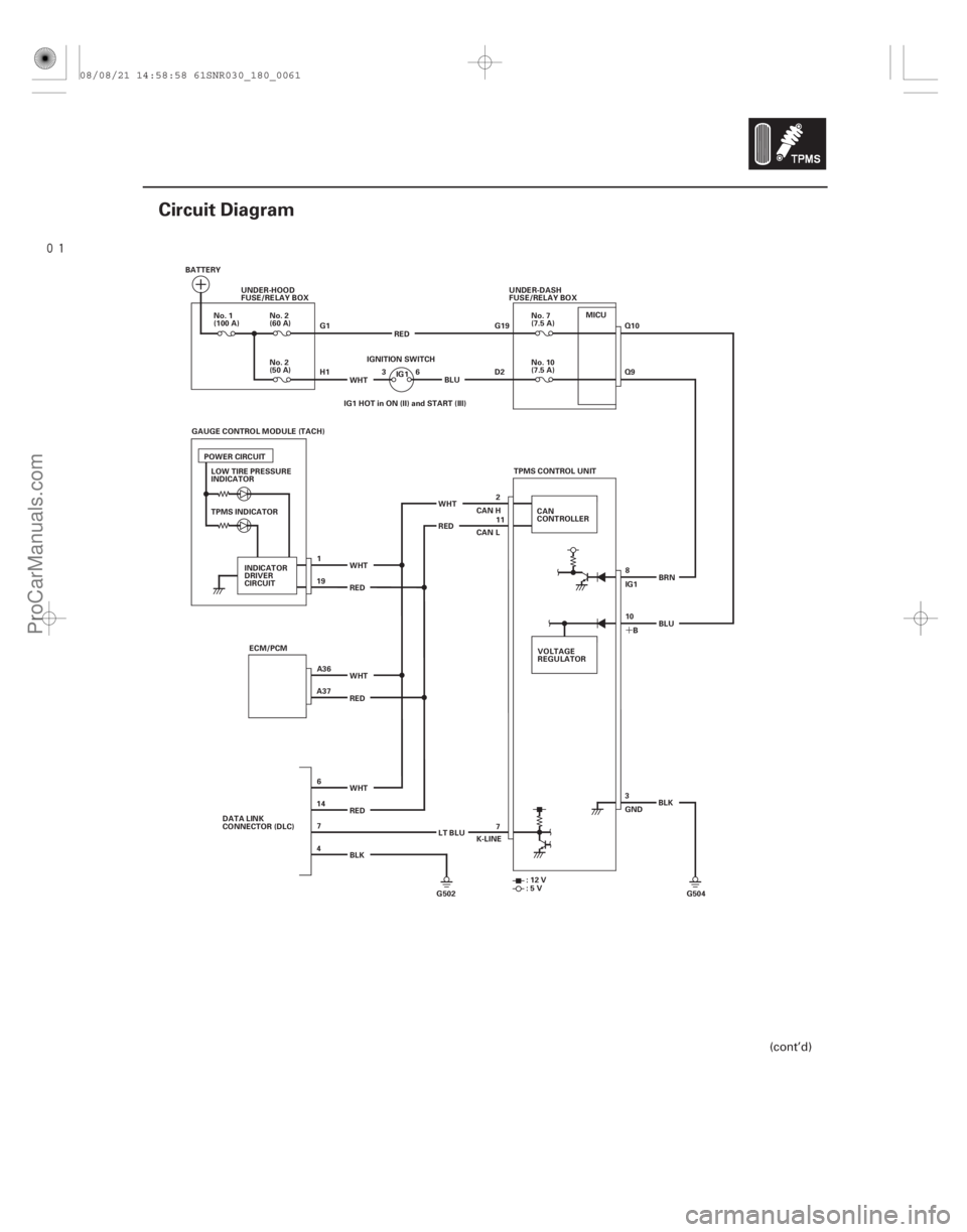
Circuit Diagram
BATTERYUNDER-HOOD
FUSE/RELAY BOX
G1
H1WHT 36
IGNITION SWITCH
No. 10
(7.5 A)
No. 2
(60 A)
No. 2
(50 A)
No. 1
(100 A)
No. 7
(7.5 A)
UNDER-DASH
FUSE/RELAY BOX
G19
D2
TPMS INDICATOR ECM/PCM WHT
RED
WHT
RED
BLK TPMS CONTROL UNIT
CAN
CONTROLLER
RED WHT RED WHT
VOLTAGE
REGULATOR8
10 IG1
B BRN
3
GND BLK
G502 G504 K-LINE
:12V
:5V
CAN H
CAN L
IG1
POWER CIRCUIT
INDICATOR
DRIVER
CIRCUIT IG1 HOT in ON (II) and START (III)
DATA LINK
CONNECTOR (DLC) LT BLUBLU
RED
BLU
2
11
LOW TIRE PRESSURE
INDICATOR
GAUGE CONTROL MODULE (TACH)
1
A36
A37 19
6
14 7
4 7Q10
Q9
MICU
(cont’d)
08/08/21 14:58:58 61SNR030_180_0061
ProCarManuals.com
DYNOMITE -2009-
Page 1475 of 2893
����
18-62TPMS
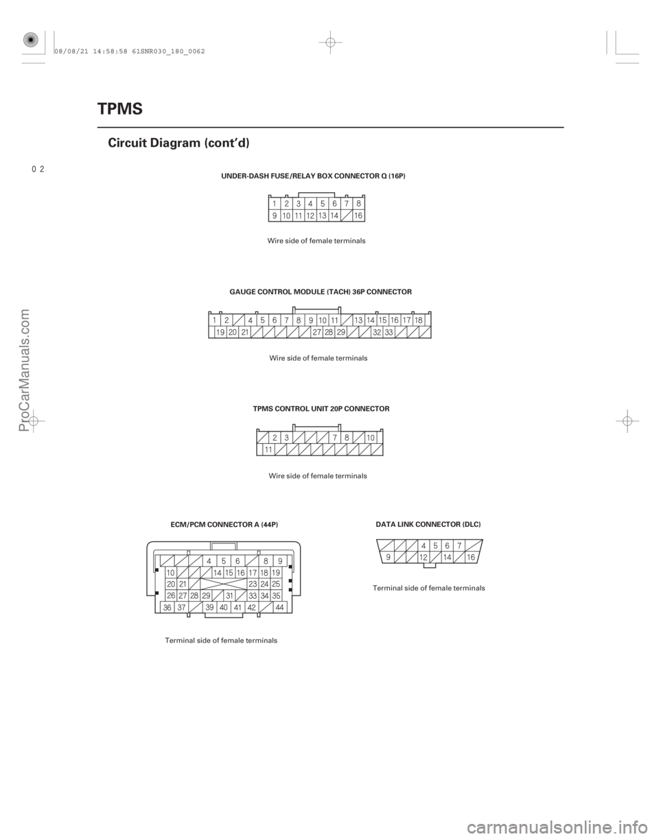
Circuit Diagram (cont’d)
DATA LINK CONNECTOR (DLC)
TPMS CONTROL UNIT 20P CONNECTOR
UNDER-DASH FUSE/RELAY BOX CONNECTOR Q (16P)
ECM/PCM CONNECTOR A (44P) GAUGE CONTROL MODULE (TACH) 36P CONNECTOR
Wire side of female terminals
Terminal side of female terminals Wire side of female terminals
Wire side of female terminals
Terminal side of female terminals
08/08/21 14:58:58 61SNR030_180_0062
ProCarManuals.com
DYNOMITE -2009-
Page 1485 of 2893
����
�µ
�µ �µ
�µ
YES
NO YES
NO
Low tire pressure indicator does not go off,
andnoDTCsarestored
18-7218-72TPMS
Symptom Troubleshooting (cont’d)")
���
�(�#�'���������������
�����
�����������������)����
�µ
�µ �µ
�µ
YES
NO YES
NO
Low tire pressure indicator does not go off,
andnoDTCsarestored
18-7218-72TPMS
Symptom Troubleshooting (cont’d)
TPMS CONTROL UNIT 20P CONNECTOR
GND (BLK) IG1 (BRN)
8. Disconnect the TPMS control unit 20P connector.
9. Measure the voltage between TPMS control unit
20P connector terminals No. 3 and No. 8.
Repair short to power in the wire between
the TPMS control unit and the No. 10 (7.5 A) fuse in
the under-dash fuse/relay box.
Check for loose terminals and poor
connections at the TPMS control unit. If necessary,
substitute a known-good TPMS control unit
(see page 18-75), and recheck. 1. Turn the ignition switch to LOCK (0).
2. Disconnect the TPMS control unit 20P connector.
3. Turn the ignition switch to ON (II).
4. Check the low tire pressure indicator for several
seconds when the ignition switch is turned ON (II).
Check for loose terminals and poor
connections at the TPMS control unit. If necessary,
substitute a known-good TPMS control unit
(see page 18-75), and recheck.
Do the troubleshooting for the gauge control
module (see page 22- 241). If necessary, substitute a
known-good gauge control module (tach) (see page
22-277), and recheck.
Wire side of female terminals
Is there battery voltage? Di d t he i nd i cat or come on, and t hen go of f ?
08/08/21 14:59:00 61SNR030_180_0072
ProCarManuals.com
DYNOMITE -2009-
Page 1486 of 2893
�����(�#����������������
�����
�����������������)����
�µ
�µ �µ
�µ
�µ
�µ
�µ
�µ
TPMS indicator does not come on, and no
DTCs are stored TPMS indica")
�(�#�'���������������
�����
�����������������)�����(�#�'���������������
�����
�����������������)����
�µ
�µ �µ
�µ
�µ
�µ
�µ
�µ
TPMS indicator does not come on, and no
DTCs are stored TPMS indicator does not go off, and no DTCs
are stored
YES
NO YES
NO
YES
NO
YES
NO
18-7318-73
1. Turn the ignition switch to LOCK (0).
2. Disconnect the TPMS control unit 20P connector.
3. Turn the ignition switch to ON (II).
4. Check the TPMS indicator for several sec
onds
when the ignition switch is turned ON (II).
Check for loose terminals and poor
connections at the TPMS control unit. If necessary,
substitute a known-good TPMS control unit
(see page 18-75), and recheck.
Do the troubleshooting for the gauge control
module (see page 22- 241). If necessary, substitute a
known-good gauge control module (tach) (see page
22-277), and recheck. NOTE: Check for gauge DTCs with the HDS (see page
22-6). If gauge DTCs are stored, troubleshoot those
DTCs first.
1. Turn the ignition switch to ON (II).
2. Check the TPMS indicator for several sec onds
when the ignition switch is turned ON (II).
The system is OK at this time.
Go to step 3.
3. Turn the ignition switch to LOCK (0).
4. Check the No. 7 (7.5 A) fuse in the under-dash fuse/ relay box.
Replace the No. 7 (7.5 A) fuse, and recheck. If
the fuse blows again, check for a short to body
ground in the wire between the TPMS control unit
and the No. 7 (7.5 A) fuse in the under-dash fuse/
relay box.
Reinstall the checked fuse, then go to step 5.
5. Check the No. 10 (7.5 A) fuse in the under-dash fuse/relay box.
Replace the No. 10 (7.5 A) fuse, and recheck.
If the fuse blows again, check for a short to body
ground in the wire between the TPMS control unit
and the No. 10 (7.5 A) fuse in the under-dash fuse/
relay box.
Reinstall the checked fuse, then go to step 6.
6. Disconnect the TPMS control unit 20P connector.
(cont’d)
Di d t he i nd i cat or come on? Di d t he i nd i cat or come on, and t hen go of f ?
Isthefuseblown?
Isthefuseblown?
08/08/21 14:59:00 61SNR030_180_0073
ProCarManuals.com
DYNOMITE -2009-
Page 1487 of 2893

TPMS CONTROL UNIT 20P CONNECTOR
B(BLU)
TPMS CONTROL UNIT 20P CONNECTOR IG1 (BRN) TPMS CONTRO")
����
��������
�´
�µ
�µ
�µ
�µ �µ
�µ
YES
NO
YES
NO YES
NO
18-74TPMS
Symptom Troubleshooting (cont’d)
TPMS CONTROL UNIT 20P CONNECTOR
B(BLU)
TPMS CONTROL UNIT 20P CONNECTOR IG1 (BRN) TPMS CONTROL UNIT 20P CONNECTOR
GND (BLK)
7. Measure the voltage between body ground and TPMS control unit 20P connector terminal No. 10.
Go to step 8.
Repair open in the wire between the TPMS
control unit and the No. 7 (7.5 A) fuse in the under-
dash fuse/relay box.
8. Turn the ignition switch to ON (II).
9. Measure the voltage between body ground and TPMS control unit 20P connector terminal No. 8.
Go to step 10.
Repair open in the wire between the TPMS
control unit and the No. 10 (7.5 A) fuse in the under-
dash fuse/relay box. 10. Turn the ignition switch to LOCK (0).
11. Reconnect the TPMS control unit 20P connector.
12. Turn the ignition switch to ON (II).
13. Measure the voltage between body ground and
TPMS control unit 20P connector terminal No. 3.
Repair open or high resistance in the wire
between the TPMS control unit and body ground
(G504).
Do the troubleshooting for the gauge control
module (see page 22-241). If the gauge control
module (tach) is OK, check for loose terminals and
poor connections at the TPMS control unit. If
necessary, substitute a known-good TPMS control
unit (see page 18-75), and recheck.
Wire side of female terminals
Wire side of female terminals Wire side of female terminals
Is there battery voltage?
Is there battery voltage? Is t her e 0.1 V or mor e?
08/08/21 14:59:01 61SNR030_180_0074
ProCarManuals.com
DYNOMITE -2009-
Page 1541 of 2893
����
�(�#�'�����������
���������������������������)�
��
19-48ABS Components
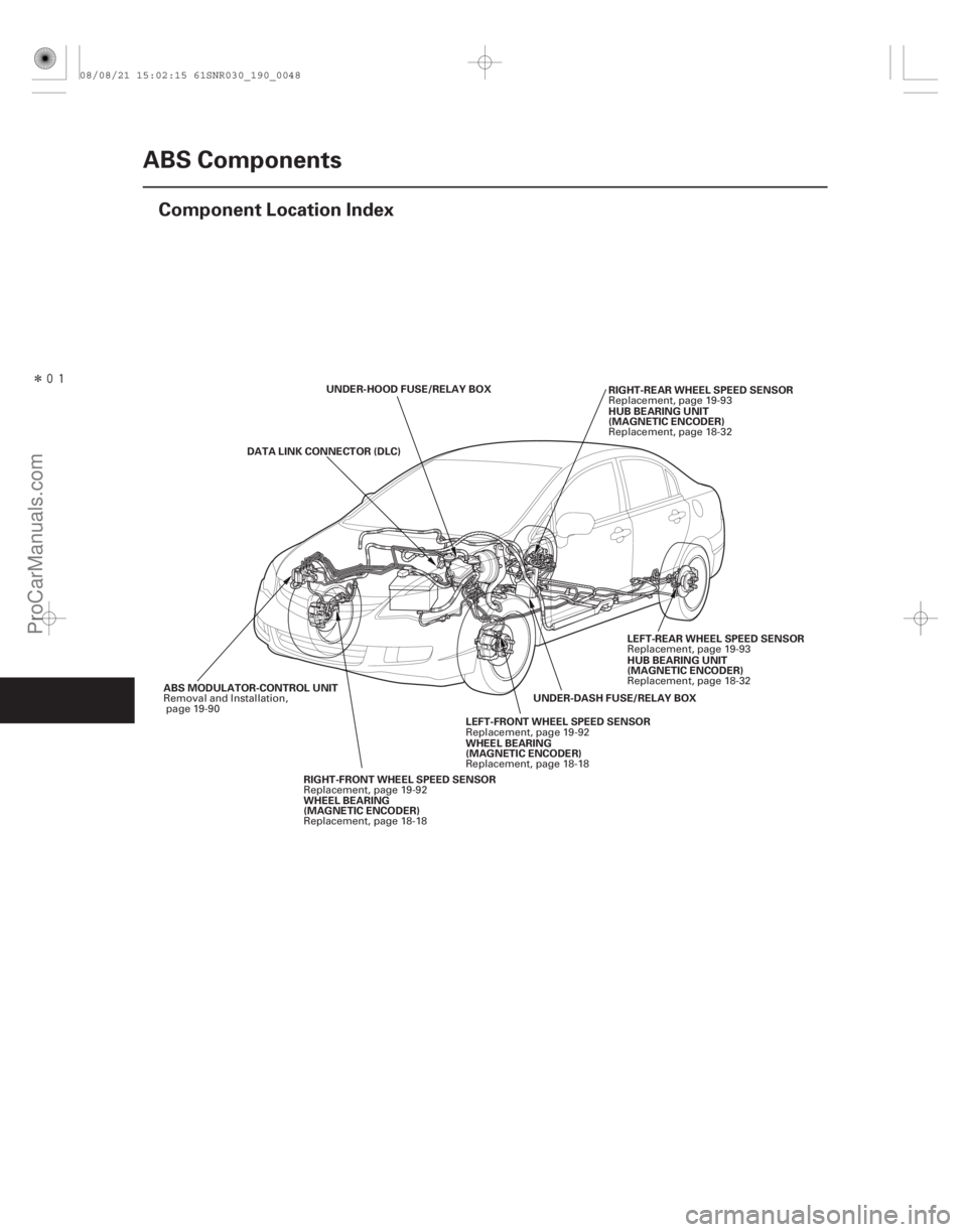
Component Location Index
UNDER-HOOD FUSE/RELAY BOX
UNDER-DASH FUSE/RELAY BOXRIGHT-REAR WHEEL SPEED SENSOR
ABS MODULATOR-CONTROL UNIT LEFT-FRONT WHEEL SPEED SENSOR
WHEEL BEARING
(MAGNETIC ENCODER)
RIGHT-FRONT WHEEL SPEED SENSOR
WHEEL BEARING
(MAGNETIC ENCODER)
DATA LINK CONNECTOR (DLC)
HUB BEARING UNIT
(MAGNETIC ENCODER)
LEFT-REAR WHEEL SPEED SENSOR
HUB BEARING UNIT
(MAGNETIC ENCODER)
Replacement, page 19-93
Removal and Installation, page 19-90
Replacement, page 19-92
Replacement, page 18-18
Replacement, page 19-92
Replacement, page 18-18 Replacement, page 18-32
Replacement, page 19-93
Replacement, page 18-32
08/08/21 15:02:15 61SNR030_190_0048
ProCarManuals.com
DYNOMITE -2009-
Page 1555 of 2893
������(�#�'�����������
���������������������������)�
��
�´
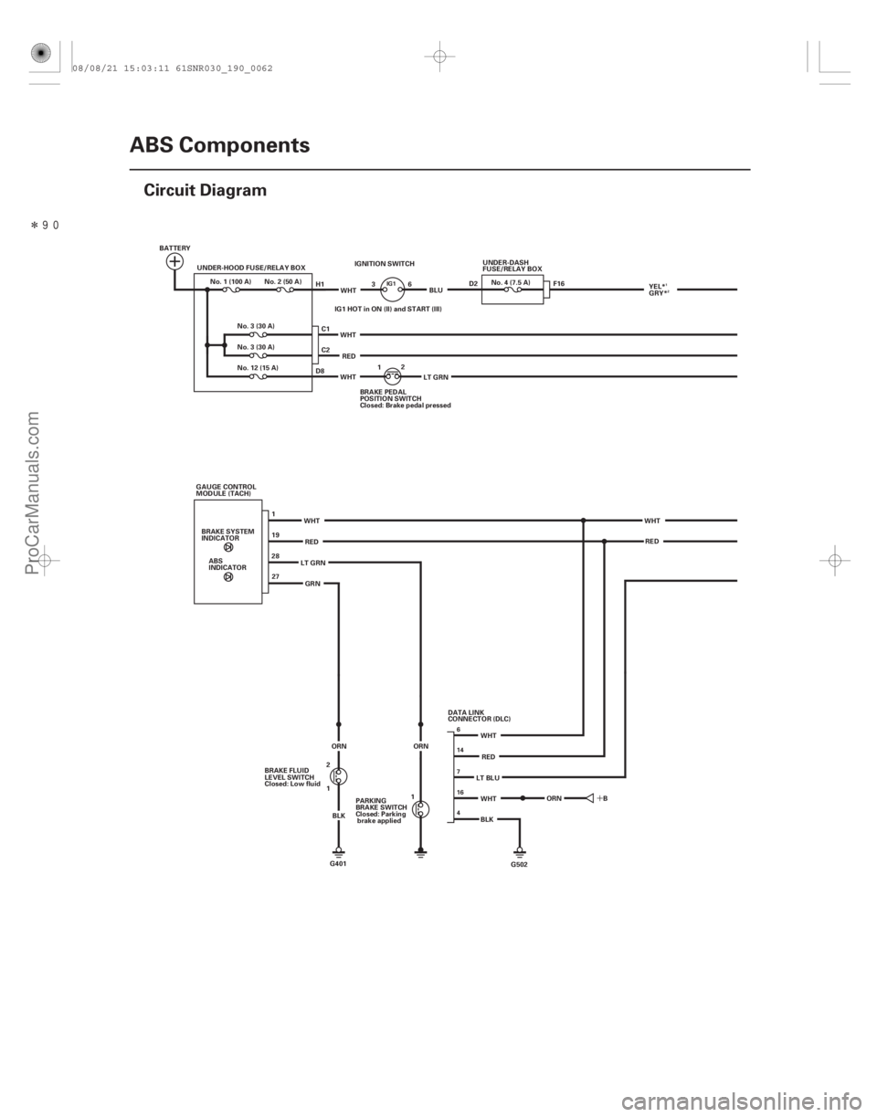
19-62ABS Components
Circuit Diagram
BATTERY
UNDER-HOOD FUSE/RELAY BOX
1
19
2827
G502
BLK
WHT
RED
WHT
WHT
RED
ABS
INDICATOR
BRAKE SYSTEM
INDICATOR
GAUGE CONTROL
MODULE (TACH)
LT GRNGRN
LT BLUWHT
RED
IGNITION SWITCH
IG1 HOT in ON (II) and START (III) WHT
LT GRN
WHT
RED BLU
WHT BRAKE PEDAL
POSITION SWITCH
Closed: Brake pedal pressed1
2
C1
C2 UNDER-DASH
FUSE/RELAY BOX
No. 4 (7.5 A)
No. 3 (30 A)
No.1(100A) No.2(50A)
No. 3 (30 A)
No. 12 (15 A) F16
B
G401
BRAKE FLUID
LEVEL SWITCH
Closed: Low fluid
1 2
BLK
ORN
H1
D8
3
6
ORN
1
PARKING
BRAKE SWITCH
Closed: Parking
brake applied DATA LINK
CONNECTOR (DLC)D2
YEL*
GRY*
ORN
6
16
4 7 14
IG11
2
08/08/21 15:03:11 61SNR030_190_0062
ProCarManuals.com
DYNOMITE -2009-