Page 17 of 68

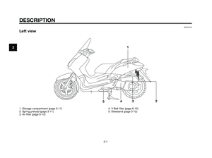
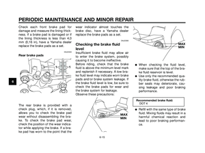
If the warning light does not come on
for a few seconds, then go off, have a
Yamaha dealer check the electrical
circuit.
EAUS1310
Immobilizer system indicator light
The electrical circuit of the indicator
light can be checked by turning the
key to “ON”.
If the indicator light does not come on
for a few seconds, then go off, have a
Yamaha dealer check the electrical
circuit.
When the key is turned to “OFF”, the
indicator light will start flashing indi-
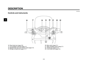
cating the immobilizer system is ena-
bled. After 24 hours have passed, the
indicator light will stop flashing,
however the immobilizer system is
still enabled.
This model is also equipped with a
self-diagnosis device for the immobi-
lizer system.
EAU11591
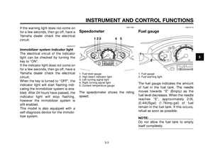
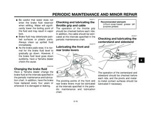
Speedometer
1. Fuel level gauge
2. High bearn indicator light
3. Left turning signal light
4. Right turning signal light
5. Coolant temperature gauge
The speedometer shows the riding
speed.
EAU12110
Fuel gauge
1. Fuel gauge
2. Fuel warning light
The fuel gauge indicates the amount
of fuel in the fuel tank. The needle
moves towards “E” (Empty) as the
fuel level decreases. When the needle
reaches “E”, approximately 2.0L
(0.44USgal) (1.76Imp.gal) of fuel
remain in the fuel tank. If this occurs,
refuel as soon as possible.
NOTE:
Do not allow the fuel tank to empty
itself completely.
1
2
123 4 5
3
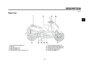
INSTRUMENT AND CONTROL FUNCTIONS
3-3
1C0-F8199-E0.qxd 13/04/2005 16:58 Página 3-3
Page 18 of 68

EAU12171
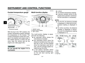
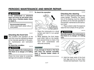
Coolant temperature gauge
1. Temperature gauge
With the key in the “ON” position, the
coolant temperature gauge indicates
the temperature of the coolant. The
coolant temperature varies with chan-
ges in the weather and engine load. If
the needle reaches or enters the red
zone, stop the vehicle and let the
engine cool. (See page 6-25.)
ECA10020
CAUTION
Do not operate the engine if it is
overheated.
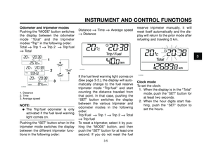
EAUM1480
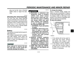
Multi-function display
1. “MODE” button
2. Multi-function display
3. “SET” button
The multi-function display is equip-
ped with the following:
�an odometer (which shows the
total distance traveled)
�two tripmeters (which show the
distance traveled since they were
last set to zero, the time passed
since the tripmeters were set to
zero, and the average speed tra-
veled during this time)
�a fuel reserve tripmeter (which
shows the distance traveled sin-
ce the fuel level warning light
came on)
�a clock
�an ambient temperature display
�a service indicator (which is dis-
played when periodic maintenan-
ce and lubrication is necessary)
NOTE:
�For the UK, the distance traveled
is displayed in miles and the tem-
perature reading is displayed in
°F.
�For other countries, the distance
traveled is displayed in kilome-
ters and the temperature reading
is displayed in °C.
1. Total
2. Trip 1
2. Trip 2
4. Trip/Fuel
123
13
INSTRUMENT AND CONTROL FUNCTIONS
3-4
1C0-F8199-E0.qxd 13/04/2005 16:58 Página 3-4
Page 19 of 68

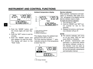
Odometer and tripmeter modes
Pushing the “MODE” button switches
the display between the odometer
mode “Total” and the tripmeter
modes “Trip” in the following order:
Total
�Trip 1 �Trip 2 �Trip/fuel
�Total
1. Distance
2. Time
3. Average speed
NOTE:
�The Trip/fuel odometer is only
activated if the fuel level warning
light comes on.
Pushing the “SET” button when in the
tripmeter mode switches the display
between the different tripmeter func-
tions in the following order:Distance
�Time �Average speed
�Distance
If the fuel level warning light comes on
(See page 3-2.), the display will auto-
matically change to the fuel reserve
tripmeter mode “Trip/fuel” and start
counting the distance traveled from
that point. In that case, pushing the
“SET” button switches the display
between the various tripmeter and
odometer modes in the following
order:
Trip/Fuel
�Trip 1 �Trip 2 �Total
�Trip/fuel
To reset a tripmeter, select it by pus-
hing the “MODE” button, and then
push the “SET” button for at least one
second. If you do not reset the fuelreserve tripmeter manually, it will
reset itself automatically and the dis-
play will return to the prior mode after
refueling and traveling 5 km.
Clock mode
To set the clock:
1. When the display is in the “Total”
mode, push the “SET” button for
at least two seconds.
2. When the hour digits start flas-
hing, push the “SET” button to
set the hours.
3
INSTRUMENT AND CONTROL FUNCTIONS
3-5
1C0-F8199-E0.qxd 13/04/2005 16:58 Página 3-5
Page 20 of 68

3. Push the “MODE” button, and
the minute digits will start flas-
hing.
4. Push the “SET” button to set the
minutes.
5. Push the “MODE” button and
then release it to start the clock.
The display will return to the
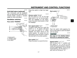
“Total” mode.Ambient temperature display1. Frost warning indicator
2. Negative symbol
3. Ambient temperature
This display shows the ambient tem-
perature from-30°C to 50°C.
The frost warning indicator “*” auto-
matically comes on if the temperature
is lower than 3°C
1. Oil change indicator
Service indicator
When periodic maintenance and lubri-
cation is necessary (See page 6-3.),
“OIL” will appear in the display until the
Service indicator reset is made.
T
o reset the service indicator:
1. Turn the key to “ON”.
2. Hold the “MODE” and “SET” but-
ton pushed for two to five
seconds.
3. Release the buttons, and the ser-
vice indicator will go off.
NOTE:
�The service indicator will come
on at the initial 1000 km and
every 3000 km thereafter.
�If periodic maintenance and
lubrication is performed before
the service indicator comes on,
the indicator must be reset as
soon as possible so that it comes
for the next periodic maintenance
and lubrication interval.
3
INSTRUMENT AND CONTROL FUNCTIONS
3-6
1C0-F8199-E0.qxd 13/04/2005 16:58 Página 3-6
Page 21 of 68

This motorcycle can be equipped
with an optional anti-theft alarm by a
Yamaha dealer. Contact a Yamaha
dealer for more information.
EAU12343
Handlebar switchesEAUS")
EAU12331
Anti-theft alarm (optional)
This motorcycle can be equipped
with an optional anti-theft alarm by a
Yamaha dealer. Contact a Yamaha
dealer for more information.
EAU12343
Handlebar switchesEAUS1300
Pass switch “PASSING”
1. Dimmer switch
2. “PASSING” switch
3. Turn signal switch
4. Horn switch
Press this switch to flash the head-
light.
EAUS1020
Dimmer switch “j/k”
Set this switch to “
j” for the high
beam and to “
k” for the low beam.
With the headlight on low beam,
press this switch downwards to flash
the headlight.
EAU12460
Turn signal switch “c/d”
To signal a right-hand turn, push this
switch to “
d”. To signal a left-hand
turn, push this switch to “
c”. When
released, the switch returns to the
center position. To cancel the turn
signal lights, push the switch in after it
has returned to the center position.
EAU12500
Horn switch “a”
Press this switch to sound the horn.
EAUM1131
Start switch “g”
1. Starting switch
2. Hazard switch
Push this switch while applying the
front or rear brake to crank the engine
with the starter.
ECA10050
CAUTION
See page 5-1 for starting instruc-
tions prior to starting the engine.
EAUM1990
Hazard switch “ ”, “h”
With the key in the “f” position, set
this switch to “ ” to turn on the
hazard lighting (simultaneous flashing
of all turn signal lights). To turn off the
hazard lighting, set this switch to “h”
and, then turn the key to “e”.
12
1
2
3
4
3
INSTRUMENT AND CONTROL FUNCTIONS
3-7
1C0-F8199-E0.qxd 13/04/2005 16:58 Página 3-7
Page 22 of 68

NOTE:
Even if the key is turned from “f” to
“e” with the hazard lighting on, the
hazard lighting will continue to flash
regardless of the hazard switch posi-
tion. To cancel the hazard lighting, the
key must be turned to “f” and the
hazard switch must be set to the “h”
position.
The hazard lighting is used in case of
an emergency or to warn other drivers
when your scooter is stopped where
it might be a traffic hazard.
ECA10060
CAUTION
Do not use the hazard light for an
extended length of time, otherwise
the battery may discharge.
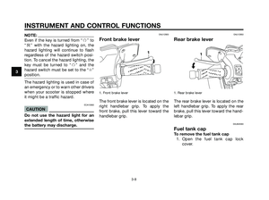
EAU12900
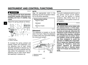
Front brake lever
1. Front brake lever
The front brake lever is located on the
right handlebar grip. To apply the
front brake, pull this lever toward the
handlebar grip.
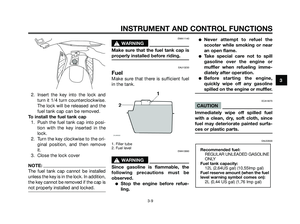
EAU12950
Rear brake lever
1. Rear brake lever
The rear brake lever is located on the
left handlebar grip. To apply the rear
brake, pull this lever toward the hand-
lebar grip.
EAUM2080
Fuel tank cap
To remove the fuel tank cap
1. Open the fuel tank cap lock
cover.
11
3
INSTRUMENT AND CONTROL FUNCTIONS
3-8
1C0-F8199-E0.qxd 13/04/2005 16:58 Página 3-8
Page 23 of 68

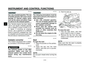
2. Insert the key into the lock and
turn it 1/4 turn counterclockwise.
The lock will be released and the
fuel tank cap can be removed.
To install the fuel tank cap
1. Push the fuel tank cap into posi-
tion with the key inserted in the
lock.
2. Turn the key clockwise to the ori-
ginal position, and then remove
it.
3. Close the lock cover
NOTE:
The fuel tank cap cannot be installed
unless the key is in the lock. In addition,
the key cannot be removed if the cap is
not properly installed and locked.
EWA11140
s s
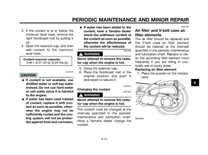
WARNING
Make sure that the fuel tank cap is
properly installed before riding.
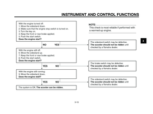
EAU13230
Fuel
Make sure that there is sufficient fuel
in the tank.
1. Filler tube
2. Fuel level
EWA10990
s s
WARNING
Since gasoline is flammable, the
following precautions must be
observed.
�Stop the engine before refue-
ling.
�Never attempt to refuel the
scooter while smoking or near
an open flame.
�Take special care not to spill
gasoline over the engine or
muffler when refueling imme-
diately after operation.
�Before starting the engine,
quickly wipe off any gasoline
spilled on the engine or muffler.
ECA10070
CAUTION
Immediately wipe off spilled fuel
with a clean, dry, soft cloth, since
fuel may deteriorate painted surfa-
ces or plastic parts.
EAU33500
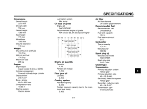
Recommended fuel:
REGULAR UNLEADED GASOLINE
ONLY
Fuel tank capacity:
12L (2,64US gal) (10,55Imp gal)
Fuel reserve amount (when the fuel
level warning symbol comes on):
2L (0,44 US gal) (1,76 Imp gal)
3
INSTRUMENT AND CONTROL FUNCTIONS
3-9
1C0-F8199-E0.qxd 13/04/2005 16:58 Página 3-9
Page 24 of 68

ECA11400
CAUTION
Use only unleaded gasoline. The use
of leaded gasoline will cause severe
damage to internal engine parts,
such as the valves and piston rings,
as well as to the exhaust system.
Your Yamaha engine has been desig-
ned to use regular unleaded gasoline
with a research octane number of 91
or higher. If knocking (or pinging)
occurs, use a gasoline of a different
brand or premium unleaded fuel. Use
of unleaded fuel will extend spark plug
life and reduce maintenance costs.
EAU13431
Catalytic converter
This model is equipped with a cataly-
tic converter in the exhaust system.
EWA10860
s s
WARNING
The exhaust system is hot after
operation. Make sure that the
exhaust system has cooled down
before doing any maintenance
work.
ECA10700
CAUTION
The following precautions must be
observed to prevent a fire hazard or
other damages.
�Use only unleaded gasoline.
The use of leaded gasoline will
cause unrepairable damage to
the catalytic converter.
�Never park the vehicle near
possible fire hazards such as
grass or other materials that
easily burn.
�Do not allow the engine to idle
too long.
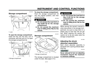
EAU13931
Seat
To open the seat
1. Place the scooter on the centers-
tand.
2. Insert the key into the main
switch, and then turn it counter-
clockwise.
NOTE:
Do not push inward when turning the
key.
3. Fold the seat up.
To close the seat
1. Fold the seat down, and then
push it down to lock it in place.
2. Remove the key from the main
switch if the scooter will be left
unattended.
NOTE:
Make sure that the seat is properly
secured before riding.
3
INSTRUMENT AND CONTROL FUNCTIONS
3-10
1C0-F8199-E0.qxd 13/04/2005 16:58 Página 3-10