Page 2044 of 5135
A78516
A78459
14±28
±
ENGINE MECHANICAL PARTIAL ENGINE ASSY(1ZZ±FE/3ZZ±FE)
AVENSIS REPAIR MANUAL (RM1018E)
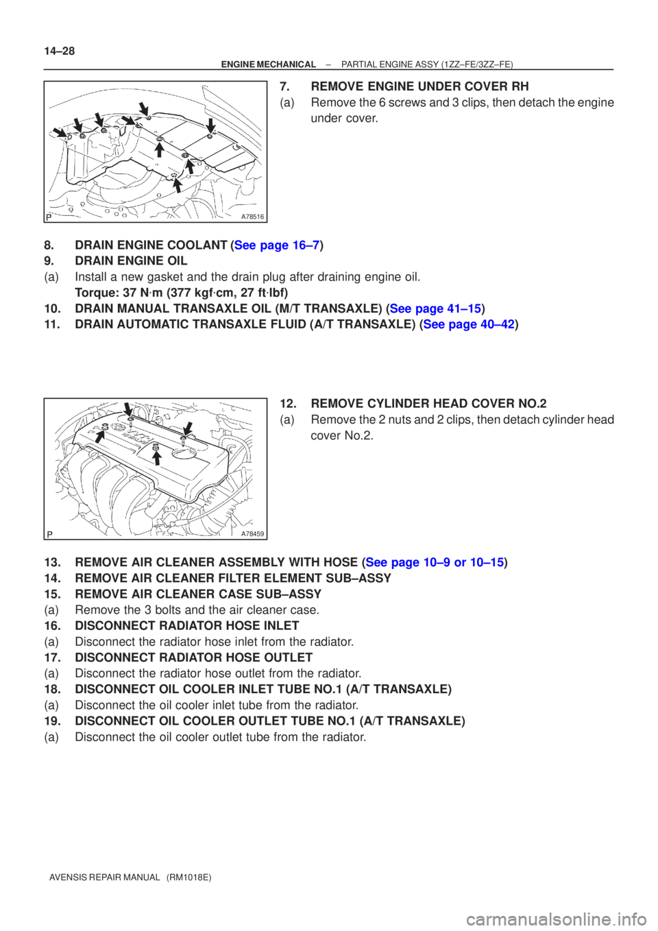
7.REMOVE ENGINE UNDER COVER RH
(a)Remove the 6 screws and 3 clips, then detach the engine under cover.
8.DRAIN ENGINE COOLANT(See page 16±7)
9. DRAIN ENGINE OIL
(a) Install a new gasket and the drain plug after draining engine oil. Torque: 37 N �m (377 kgf �cm, 27 ft �lbf)
10.DRAIN MANUAL TRANSAXLE OIL (M/T TRANSAXLE) (See page 41±15)
11.DRAIN AUTOMATIC TRANSAXLE FLUID (A/T TRANSAXLE) (See page 40±42)
12. REMOVE CYLINDER HEAD COVER NO.2
(a) Remove the 2 nuts and 2 clips, then detach cylinder headcover No.2.
13.REMOVE AIR CLEANER ASSEMBLY WITH HOSE (See page 10±9 or 10±15)
14. REMOVE AIR CLEANER FILTER ELEMENT SUB±ASSY
15. REMOVE AIR CLEANER CASE SUB±ASSY
(a) Remove the 3 bolts and the air cleaner case.
16. DISCONNECT RADIATOR HOSE INLET
(a) Disconnect the radiator hose inlet from the radiator.
17. DISCONNECT RADIATOR HOSE OUTLET
(a) Disconnect the radiator hose outlet from the radiator.
18. DISCONNECT OIL COOLER INLET TUBE NO.1 (A/T TRANSAXLE)
(a) Disconnect the oil cooler inlet tube from the radiator.
19. DISCONNECT OIL COOLER OUTLET TUBE NO.1 (A/T TRANSAXLE)
(a) Disconnect the oil cooler outlet tube from the radiator.
Page 2046 of 5135
A77338
A79320
A79296
A60622
14±30
±
ENGINE MECHANICAL PARTIAL ENGINE ASSY (1ZZ±FE/3ZZ±FE)
AVENSIS REPAIR MANUAL (RM1018E)
32. SEPARATE FLOOR SHIFT CABLE TRANSMISSION CONTROL SELECT (M/T TRANSAXLE) (See page 41±15)
33. SEPARATE FLOOR SHIFT CABLE TRANSMISSION CONTROL SHIFT (M/T TRANSAXLE)
(See page 41±15)
34. SEPARATE FLOOR SHIFT CABLE TRANSMISSION CONTROL SHIFT (A/T TRANSAXLE) (See page 40±11)
35.SEPARATE CLUTCH RELEASE CYLINDER ASSY (M/T TRANSAXLE) (See page 41±15)
36.REMOVE GLOVE COMPARTMENT DOOR ASSY (See page 71±11)
37. REMOVE INSTRUMENT PANEL UNDER COVER SUB±ASSY NO.2
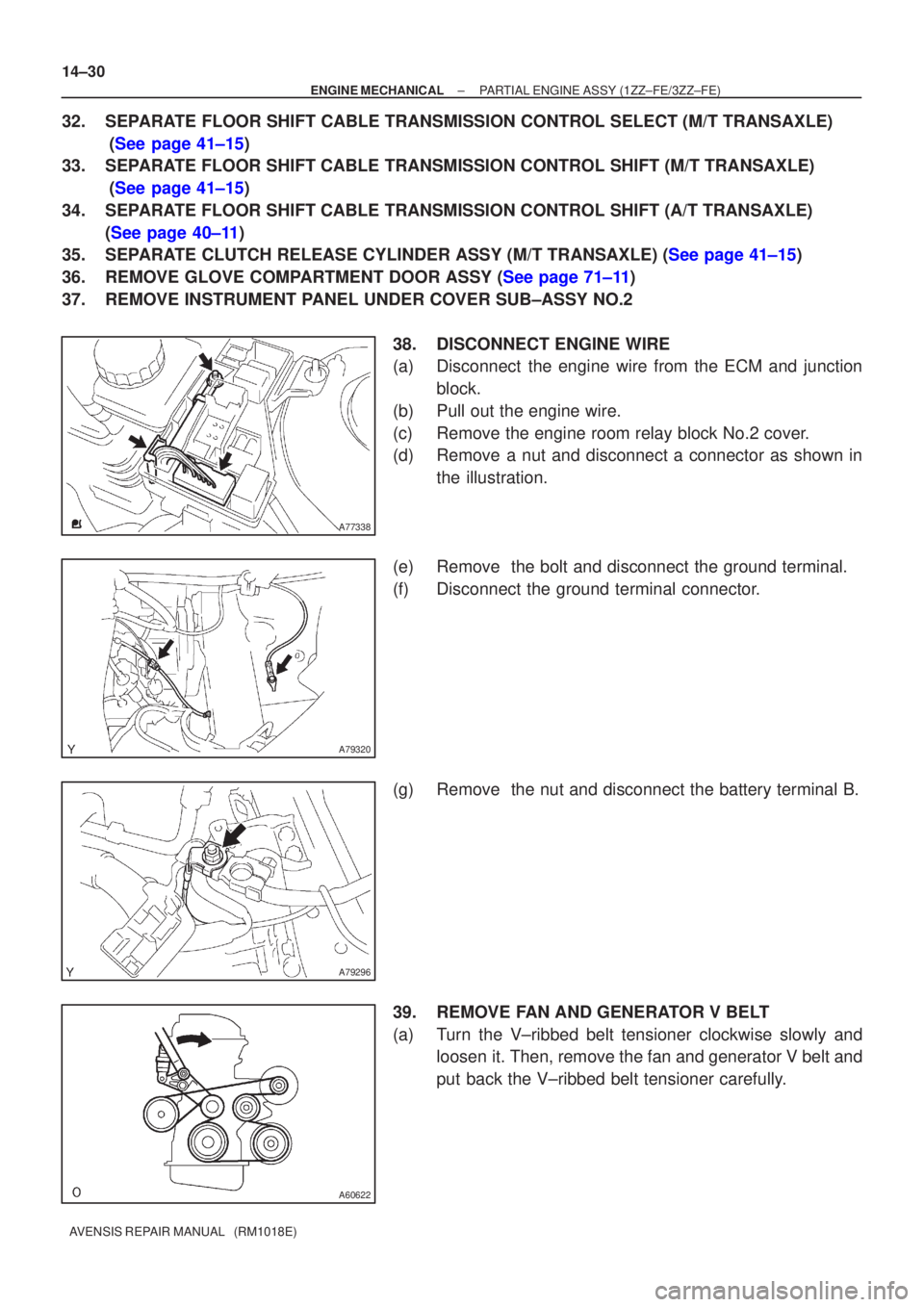
38. DISCONNECT ENGINE WIRE
(a) Disconnect the engine wire from the ECM and junctionblock.
(b) Pull out the engine wire.
(c) Remove the engine room relay block No.2 cover.
(d) Remove a nut and disconnect a connector as shown in the illustration.
(e) Remove the bolt and disconnect the ground terminal.
(f) Disconnect the ground terminal connector.
(g) Remove the nut and disconnect the battery terminal B.
39. REMOVE FAN AND GENERATOR V BELT
(a) Turn the V±ribbed belt tensioner clockwise slowly and loosen it. Then, remove the fan and generator V belt and
put back the V±ribbed belt tensioner carefully.
Page 2049 of 5135
A76718
A76719
A62838SST
A62838SST
±
ENGINE MECHANICAL PARTIAL ENGINE ASSY (1ZZ±FE/3ZZ±FE)
14±33
AVENSIS REPAIR MANUAL (RM1018E)
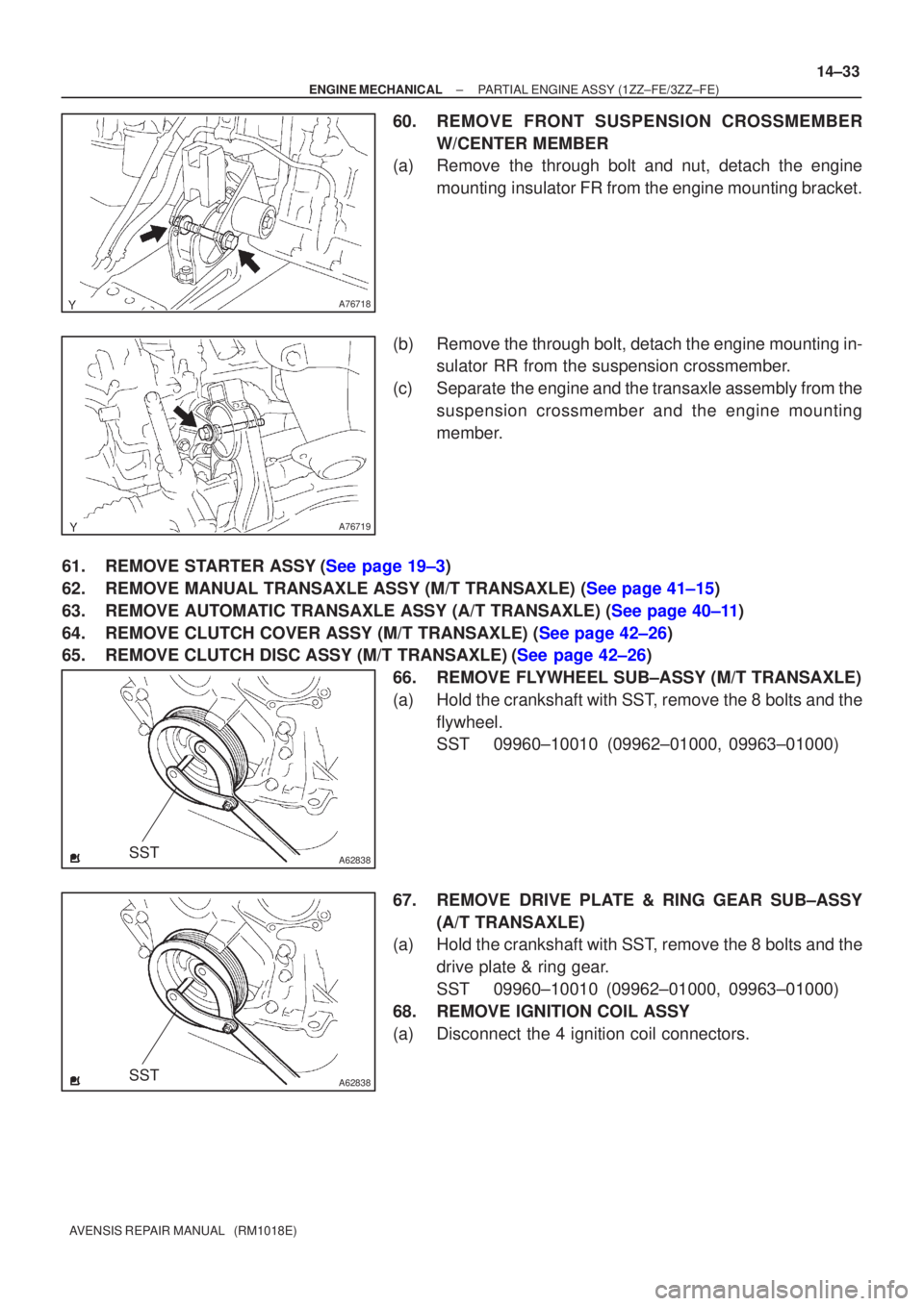
60. REMOVE FRONT SUSPENSION CROSSMEMBER
W/CENTER MEMBER
(a) Remove the through bolt and nut, detach the engine
mounting insulator FR from the engine mounting bracket.
(b) Remove the through bolt, detach the engine mounting in- sulator RR from the suspension crossmember.
(c) Separate the engine and the transaxle assembly from the suspension crossmember and the engine mounting
member.
61.REMOVE STARTER ASSY(See page 19±3)
62.REMOVE MANUAL TRANSAXLE ASSY (M/T TRANSAXLE) (See page 41±15)
63.REMOVE AUTOMATIC TRANSAXLE ASSY (A/T TRANSAXLE) (See page 40±11)
64.REMOVE CLUTCH COVER ASSY (M/T TRANSAXLE) (See page 42±26)
65.REMOVE CLUTCH DISC ASSY (M/T TRANSAXLE)(See page 42±26) 66. REMOVE FLYWHEEL SUB±ASSY (M/T TRANSAXLE)
(a) Hold the crankshaft with SST, remove the 8 bolts and theflywheel.
SST 09960±10010 (09962±01000, 09963±01000)
67. REMOVE DRIVE PLATE & RING GEAR SUB±ASSY (A/T TRANSAXLE)
(a) Hold the crankshaft with SST, remove the 8 bolts and the
drive plate & ring gear.
SST 09960±10010 (09962±01000, 09963±01000)
68. REMOVE IGNITION COIL ASSY
(a) Disconnect the 4 ignition coil connectors.
Page 2058 of 5135
A62204
1
5
3
82
6
4
7
A76719
A76718
A76717
14±42
±
ENGINE MECHANICAL PARTIAL ENGINE ASSY (1ZZ±FE/3ZZ±FE)
AVENSIS REPAIR MANUAL (RM1018E)
(b) Clean the bolt and bolt hole.
(c) Apply adhesive to the bolts. Adhesive:
Part No. 09330±00070, THREE BOND or equivalent.
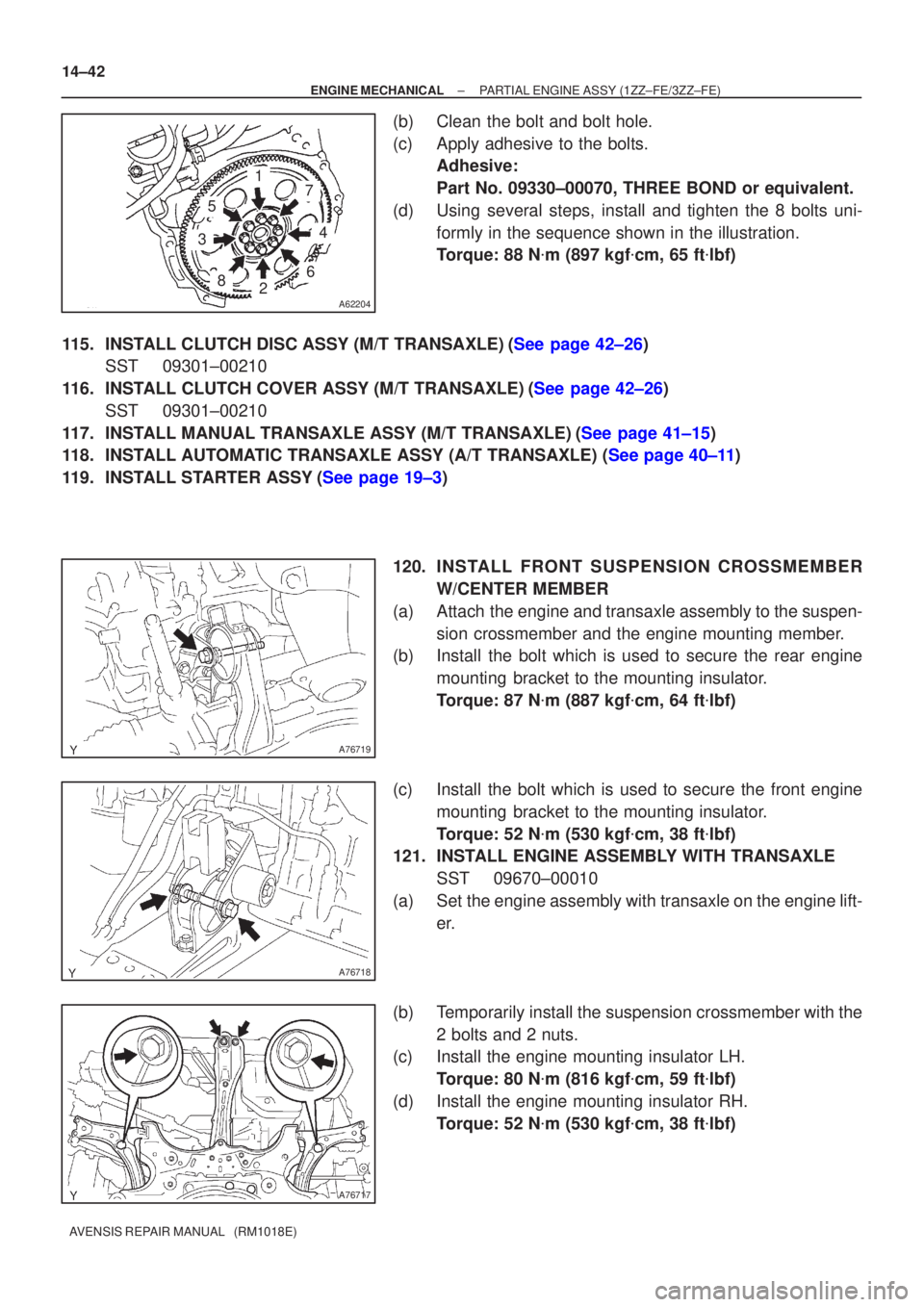
(d) Using several steps, install and tighten the 8 bolts uni- formly in the sequence shown in the illustration.
Torque: 88 N �m (897 kgf �cm, 65 ft �lbf)
115.INSTALL CLUTCH DISC ASSY (M/T TRANSAXLE)(See page 42±26) SST 09301±00210
116.INSTALL CLUTCH COVER ASSY (M/T TRANSAXLE)(See page 42±26) SST 09301±00210
117.INSTALL MANUAL TRANSAXLE ASSY (M/T TRANSAXLE)(See page 41±15)
118.INSTALL AUTOMATIC TRANSAXLE ASSY (A/T TRANSAXLE) (See page 40±11)
119.INSTALL STARTER ASSY(See page 19±3)
120. INS TALL FRO NT SUSPENSION CROSSMEMBER
W/CENTER MEMBER
(a) Attach the engine and transaxle assembly to the suspen- sion crossmember and the engine mounting member.
(b) Install the bolt which is used to secure the rear engine
mounting bracket to the mounting insulator.
Torque: 87 N �m (887 kgf �cm, 64 ft �lbf)
(c) Install the bolt which is used to secure the front engine mounting bracket to the mounting insulator.
Torque: 52 N �m (530 kgf �cm, 38 ft �lbf)
121. INSTALL ENGINE ASSEMBLY WITH TRANSAXLE
SST 09670±00010
(a) Set the engine assembly with transaxle on the engine lift- er.
(b) Temporarily install the suspension crossmember with the 2 bolts and 2 nuts.
(c) Install the engine mounting insulator LH.
Torque: 80 N �m (816 kgf �cm, 59 ft �lbf)
(d) Install the engine mounting insulator RH. Torque: 52 N �m (530 kgf �cm, 38 ft �lbf)
Page 2059 of 5135
A76717
A
B
A
B
A76716
AA
BBBBBB
±
ENGINE MECHANICAL PARTIAL ENGINE ASSY (1ZZ±FE/3ZZ±FE)
14±43
AVENSIS REPAIR MANUAL (RM1018E)
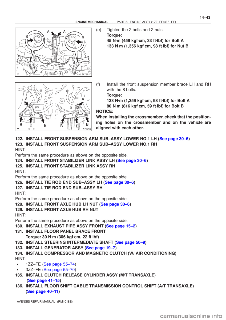
(e) Tighten the 2 bolts and 2 nuts.
Torque:
45 N�m (459 kgf �cm, 33 ft �lbf) for Bolt A
133 N �m (1,356 kgf �cm, 98 ft �lbf) for Nut B
(f) Install the front suspension member brace LH and RH with the 8 bolts.
Torque:
133 N �m (1,356 kgf �cm, 98 ft �lbf) for Bolt A
80 N �m (816 kgf �cm, 59 ft �lbf) for Bolt B
NOTICE:
When installing the crossmember, check that the position-
ing holes on the crossmember and on the vehicle are
aligned with each other.
122.INSTALL FRONT SUSPENSION ARM SUB±ASSY LOWER NO.1 LH (See page 30±6)
123. INSTALL FRONT SUSPENSION ARM SUB±ASSY LOWER NO.1 RH
HINT:
Perform the same procedure as above on the opposite side.
124.INSTALL FRONT STABILIZER LINK ASSY LH (See page 30±6)
125. INSTALL FRONT STABILIZER LINK ASSY RH
HINT:
Perform the same procedure as above on the opposite side.
126.INSTALL TIE ROD END SUB±ASSY LH (See page 30±6)
127. INSTALL TIE ROD END SUB±ASSY RH
HINT:
Perform the same procedure as above on the opposite side.
128.INSTALL FRONT AXLE HUB LH NUT (See page 30±6)
129. INSTALL FRONT AXLE HUB RH NUT
HINT:
Perform the same procedure as above on the opposite side.
130.INSTALL EXHAUST PIPE ASSY FRONT (See page 15±2)
131. INSTALL FLOOR PANEL BRACE FRONT Torque: 30 N �m (306 kgf �cm, 22 ft �lbf)
132.INSTALL STEERING INTERMEDIATE SHAFT (See page 50±9)
133.INSTALL GENERATOR ASSY (See page 19±7)
134. INSTALL COMPRESSOR AND MAGNETIC CLUTCH (W/ AIR CONDITIONING)
HINT:
�1ZZ±FE (See page 55±74)
�3ZZ±FE (See page 55±70)
135. INSTALL CLUTCH RELEASE CYLINDER ASSY (M/T TRANSAXLE) (See page 41±15)
136. INSTALL FLOOR SHIFT CABLE TRANSMISSION CONTROL SHIFT (A/T TRANSAXLE) (See page 40±11)
Page 2103 of 5135
141CO±01
A62838SST
A62838SST
A62202
Cut Position
A62203
SST
14±98
±
ENGINE MECHANICAL ENGINE REAR OIL SEAL(1ZZ±FE/3ZZ±FE)
AVENSIS REPAIR MANUAL (RM1018E)
ENGINE REAR OIL SEAL(1ZZ±FE/3ZZ±FE)
REPLACEMENT
1.REMOVE MANUAL TRANSAXLE ASSY (M/T TRANSAXLE) (See page 41±15)
2.REMOVE AUTOMATIC TRANSAXLE ASSY (A/T TRANSAXLE) (See page 40±11)
3.REMOVE CLUTCH COVER ASSY (M/T TRANSAXLE) (See page 42±26)
4.REMOVE CLUTCH DISC ASSY (M/T TRANSAXLE) (See page 42±26) 5. REMOVE FLYWHEEL SUB±ASSY (M/T TRANSAXLE)
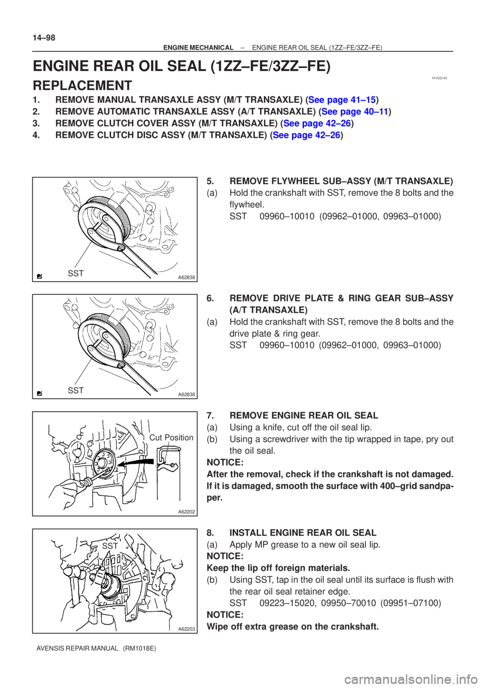
(a) Hold the crankshaft with SST, remove the 8 bolts and theflywheel.
SST 09960±10010 (09962±01000, 09963±01000)
6. REMOVE DRIVE PLATE & RING GEAR SUB±ASSY (A/T TRANSAXLE)
(a) Hold the crankshaft with SST, remove the 8 bolts and the drive plate & ring gear.
SST 09960±10010 (09962±01000, 09963±01000)
7. REMOVE ENGINE REAR OIL SEAL
(a) Using a knife, cut off the oil seal lip.
(b) Using a screwdriver with the tip wrapped in tape, pry out the oil seal.
NOTICE:
After the removal, check if the crankshaft is not damaged.
If it is damaged, smooth the surface with 400±grid sandpa-
per.
8. INSTALL ENGINE REAR OIL SEAL
(a) Apply MP grease to a new oil seal lip.
NOTICE:
Keep the lip off foreign materials.
(b) Using SST, tap in the oil seal until its surface is flush with the rear oil seal retainer edge.
SST 09223±15020, 09950±70010 (09951±07100)
NOTICE:
Wipe off extra grease on the crankshaft.
Page 2105 of 5135
14±100
±
ENGINE MECHANICAL ENGINE REAR OIL SEAL(1ZZ±FE/3ZZ±FE)
AVENSIS REPAIR MANUAL (RM1018E)
13.INSTALL MANUAL TRANSAXLE ASSY (M/T TRANSAXLE) (See page 41±15)
14.INSTALL AUTOMATIC TRANSAXLE ASSY (A/T TRANSAXLE) (See page 40±11)
Page 2505 of 5135
F45155
������F40197
Inner SideRear
Side
±
FRONT SUSPENSION STABILIZER BAR FRONT
26±27
AVENSIS REPAIR MANUAL (RM1018E)
10. SUSPEND ENGINE ASSY
(a)1ZZ, 3ZZ Engine: See page 41±15
(b)1AZ Engine: See page 41±24
(c)1CD Engine: See page 41±33
11.REMOVE FRONT SUSPENSION MEMBER BRACE REAR LH (See page 26±16)
12. REMOVE FRONT SUSPENSION MEMBER BRACE REAR RH
HINT:
Remove the RH side by the same procedures as the LH side.
13.SEPARATE FRONT SUSPENSION CROSSMEMBER SUB±ASSY (See page 26±16)
14. REMOVE FRONT STABILIZER BRACKET NO.1 LH
(a) Remove the 2 bolts and the front stabilizer bracket No.1 LH.
15. REMOVE FRONT STABILIZER BRACKET NO.1 RH
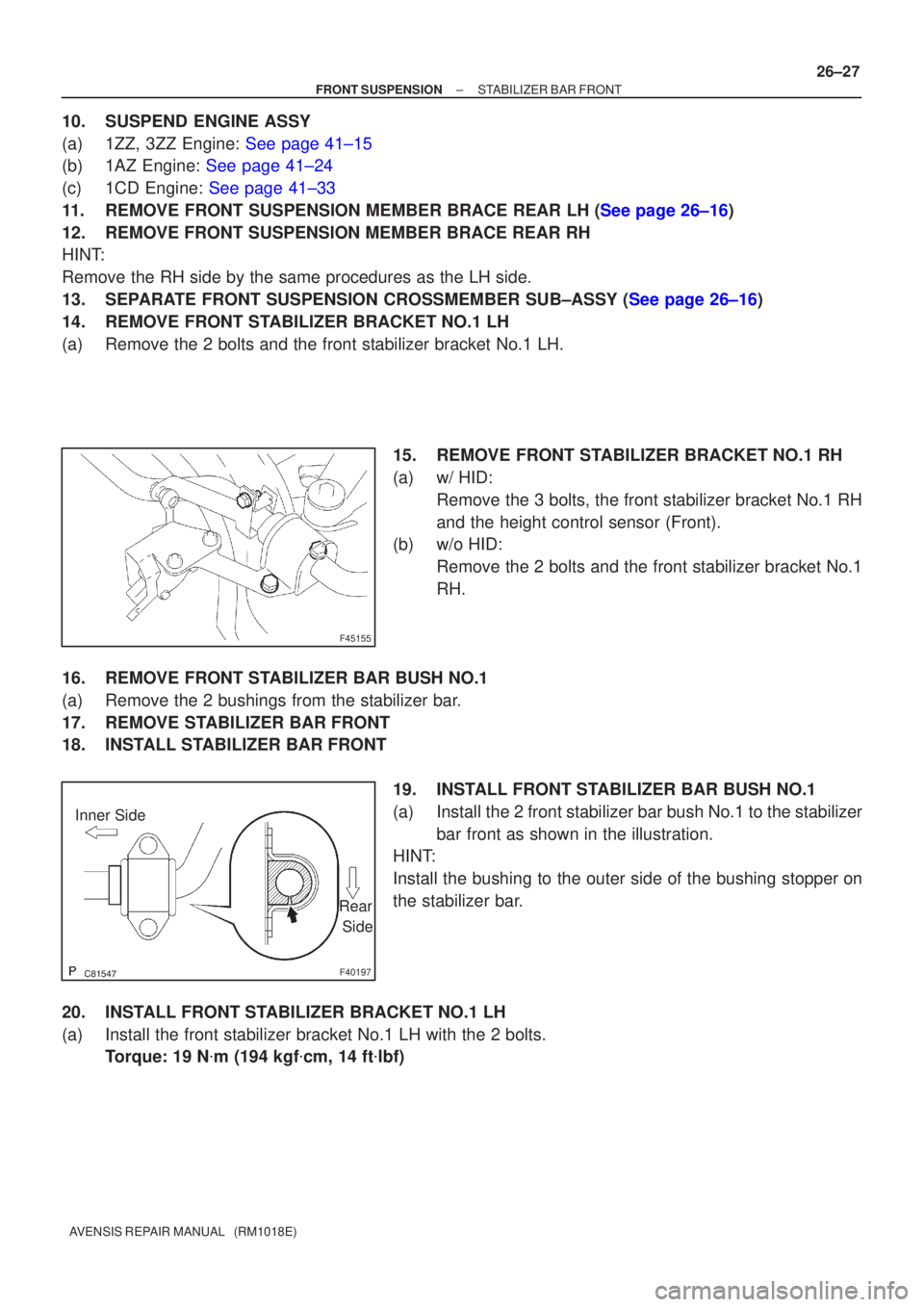
(a) w/ HID:Remove the 3 bolts, the front stabilizer bracket No.1 RH
and the height control sensor (Front).
(b) w/o HID:
Remove the 2 bolts and the front stabilizer bracket No.1
RH.
16. REMOVE FRONT STABILIZER BAR BUSH NO.1
(a) Remove the 2 bushings from the stabilizer bar.
17. REMOVE STABILIZER BAR FRONT
18. INSTALL STABILIZER BAR FRONT 19. INSTALL FRONT STABILIZER BAR BUSH NO.1
(a) Install the 2 front stabilizer bar bush No.1 to the stabilizerbar front as shown in the illustration.
HINT:
Install the bushing to the outer side of the bushing stopper on
the stabilizer bar.
20. INSTALL FRONT STABILIZER BRACKET NO.1 LH
(a) Install the front stabilizer bracket No.1 LH with the 2 bolts. Torque: 19 N �m (194 kgf �cm, 14 ft �lbf)