Page 2985 of 5135

10. INSTRUMENT PANEL AIRBAG ASSY (VEHICLE IN- VOLVED IN COLLISION AND AIRBAG IS NO")
H42657
H42659
60±14
±
SUPPLEMENTAL RESTRAINT SYSTEM SUPPLEMENTAL RESTRAINT SYSTEM
AVENSIS REPAIR MANUAL (RM1018E)
10. INSTRUMENT PANEL AIRBAG ASSY (VEHICLE IN- VOLVED IN COLLISION AND AIRBAG IS NOT
DEPLOYED)
(a)Do a diagnostic system check (See page 05±1184).
(b) Do a visual check of the instrument panel airbag assy re- moved from the vehicle:
�Cuts, minute cracks or marked discoloration on the
instrument panel airbag assy.
HINT:
�Never repair it in order for reuse or replacement.
�There should be no interference between the horn button
assy and steering wheel assy, and the clearance should
be uniform all the around when the new horn button assy
is installed on the steering wheel assy.
CAUTION:
For removal and installation procedures of the horn button
assy, see ºReplacementº on page 60±54, and be sure to fol-
low the correct procedure.
11. AIRBAG SENSOR ASSY CENTER (VEHICLE NOT INVOLVED IN COLLISION)
(a)Do a diagnostic system check (See page 05±1184).
12. AIRBAG SENSOR ASSY CENTER (VEHICLE INVOLVED IN COLLISION AND AIRBAG IS NOT DEPLOYED)
(a)Do a diagnostic system check (See page 05±1184).
13. AIRBAG SENSOR ASSY CENTER (VEHICLE INVOLVED IN COLLISION AND AIRBAG IS
DEPLOYED)
(a)Replace the airbag sensor assy center (See page 60±62).
14. AIRBAG FRONT SENSOR (VEHICLE NOT INVOLVED IN COLLISION)
(a)Do a diagnostic system check (See page 05±1184).
15. AIRBAG FRONT SENSOR (VEHICLE INVOLVED IN COLLISION)
(a)Do a diagnostic system check (See page 05±1184).
(b) When the headlamp of the vehicle or its periphery is damaged, check if t\
here is any damage to the airbag front sensor. If there are any defects as mentioned below, replace the airbag front sensor with
a new one:
If there are any defects as mentioned below, replace the airbag front sensor with a new one:
�Cracks, dents or chips in the case.
�Cracks, dents, chips and scratches in the connector.
�Peeling off of the label or damage to the serial number.
16. AIRBAG FRONT SENSOR (VEHICLE INVOLVED IN COLLISION AND AIRBAG IS DEPLOYED)
(a)Replace the airbag front sensor assy (See page 60±64).
17. SIDE AIRBAG SENSOR ASSY (VEHICLES NOT INVOLVED IN COLLISION)
(a)Do a diagnostic system check (See page 05±1184).
Page 3056 of 5135

LIGHTING SYSTEM
PRECAUTION
1. PRECAUTION OF HEADLIGHT BULB REPLACEMENT
(a) When any defects such as deformation, crack, den")
650NC±02
± LIGHTINGLIGHTING SYSTEM
65±1
AVENSIS REPAIR MANUAL (RM1018E)
LIGHTING SYSTEM
PRECAUTION
1. PRECAUTION OF HEADLIGHT BULB REPLACEMENT
(a) When any defects such as deformation, crack, dent, chipping, etc. are identified on the discharge
headlight (especially, on the light control ECU), replace it with a new one.
(b) Even if the operation seems to be normal, the fail±safe function may be defective.
(c) Be careful not to scratch on drop bulbs of the discharge headlamp and halogen bulbs (for headlamp
and fog lamp), as they have pressurized gas inside and can be easily broken.
(d) Touching the HV socket of the discharge headlight with the headlight dimmer switch ON could gener-
ate momentary high voltage of 20,000 V and lead to a serious injury.
(e) Never connect a tester to the high voltage socket of the discharge headlight for measurement, as this
leads to a serious injury because of high voltage.
(f) When performing operation related to the discharge headlight, keep it away from water including rain,
turn off the light control switch, and disconnect the battery terminal and the connector of the light control
ECU in advance to avoid electric shock.
(g) When performing operation related to the discharge headlight, start it after assembling is completed
and never turn the lights on without a bulb installed.
(h) Do not turn the discharge headlight on using another power source except vehicle's.
Page 3096 of 5135
650T5±01
I35250
65±30
±
LIGHTING HEADLAMP LEVELING ECU ASSY
AVENSIS REPAIR MANUAL (RM1018E)
HEADLAMP LEVELING ECU ASSY
REPLACEMENT
1. REMOVE GLOVE COMPARTMENT DOOR ASSY (LHD STEERING POSITION TYPE) (See page 71±11)
2.REMOVE FUSE BOX OPENING COVER (RHD STEERING POSITION TYPE) (See page 71±11)
3. REMOVE LIGHT CONTROL ECU
(a) Disconnect the connector.
(b) Remove the bolt and headlamp leveling ECU assy.
4. INSTALL LIGHT CONTROL ECU
(a) Install the headlamp leveling ECU assy with the bolt.
(b) Connect the connector.
Page 3099 of 5135
650T2±01
I35251
I35252Claw
± LIGHTINGHEADLAMP DIMMER SWITCH ASSY
65±27
AVENSIS REPAIR MANUAL (RM1018E)
HEADLAMP DIMMER SWITCH ASSY
REPLACEMENT
1. SEPARATE STEERING COLUMN COVER LWR
(a) Remove the 3 screws and steering column cover LWR.
2. REMOVE HEADLAMP DIMMER SWITCH ASSY
(a) Disconnect the connector.
(b) Release the claw and pull out the headlamp dimmer
switch assy.
Page 3108 of 5135
650SU±01
I35241
I35242
I35243
I35254
65±16
±
LIGHTING HEADLAMP UNIT LH
AVENSIS REPAIR MANUAL (RM1018E)
REPLACEMENT
1.REMOVE FRONT SPOILER COVER LH (See page 76±3)
2.REMOVE FRONT SPOILER COVER RH (See page 76±3)
3.REMOVE FRONT BUMPER COVER (See page 76±3) 4. REMOVE HEAD LIGHT ASSY
(a) Disconnect the connector.
(b) Remove the 2 screws.
(c) Remove the headlamp assy and disengage the claw asshown in the illustration.
5. REMOVE HEADLAMP, NO.1 BULB (HALOGEN HEAD LAMP)
(a) Release the lock of the set spring and remove the head- lamp bulb No.1.
6. REMOVE DISCHARGE HEADLAMP BULB (DISCHARGE HEAD LAMP)
(a) Rotate the bulb socket cover in the direction of the arrow
and pull it of backward of the vehicle.
Page 3135 of 5135
660CS±01
������E68351
I35261
������
E68352
±
WIPER & WASHER HEADLAMP WASHER ACTUATOR SUB±ASSY LH
66±25
AVENSIS REPAIR MANUAL (RM1018E)
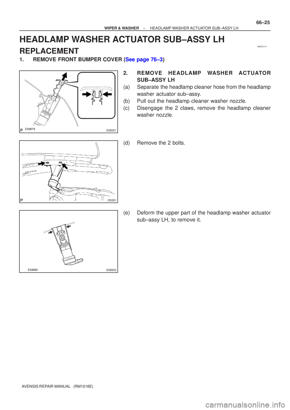
HEADLAMP WASHER ACTUATOR SUB±ASSY LH
REPLACEMENT
1.REMOVE FRONT BUMPER COVER (See page 76±3)
2. R E M O V E H E A D L A M P WA S H E R A C T U ATO RSUB±ASSY LH
(a) Separate the headlamp cleaner hose from the headlamp washer actuator sub±assy.
(b) Pull out the headlamp cleaner washer nozzle.
(c) Disengage the 2 claws, remove the headlamp cleaner washer nozzle.
(d) Remove the 2 bolts.
(e) Deform the upper part of the headlamp washer actuator sub±assy LH, to remove it.
Page 3393 of 5135

REPLACEMENT
HINT:
The installation is in the reverse order of the removal. However, when ther")
760WY±01
B67425
Claw
B67431
± EXTERIOR/INTERIOR TRIMFRONT BUMPER
76±3
AVENSIS REPAIR MANUAL (RM1018E)
REPLACEMENT
HINT:
The installation is in the reverse order of the removal. However, when there is a special point concerning
the installation, it is indicated.
1. REMOVE FRONT BUMPER COVER
(a) Put protective tape under the front fender.
HINT:
Because the spoiler covers LH and RH are assembled, remove
them together.
(b) Remove the spoiler.
(1) Remove the 9 screws and 6 claws.
(2) Remove the 6 retainers.
(3) Remove the spoiler covers LH and RH together.
(4) Remove the bolt and separate the spoiler cover RH
from the LH.
(c) Remove the 3 bolts and 2 clips.
(d) Using a screwdriver, disengage the 6 claws and remove
the bumper cover.
HINT:
Tape the screwdriver tip before use.
(e) w/ Fog lamp:
Disconnect the fog lamp connectors.
2. R E M O V E H E A D L A M P WA S H E R A C T U ATO R
SUB±ASSY LH (W/ HEADLAMP CLEANER)
(a) Remove the washer hose clip.
(b) Using a screwdriver, pry out the front washer nozzle.
HINT:
Tape the screwdriver tip before use.
(c) Remove the 2 screws and actuator.
3. REMOVE HEADLAMP WASHER ACTUATOR SUB±ASSY RH (W/ HEADLAMP CLEANER)
HINT:
Use the same procedures described for the LH side.
4. REMOVE INTERCOOLER COOLING AIR DUCT SUB±ASSY (W/ CAC 1CD±FTV ENGINE TYPE)
(a) Remove the 3 screws and air duct.
5. REMOVE FRONT BUMPER REINFORCEMENT SUB±ASSY
(a) Using a screwdriver, remove the wire harness.
(b) Remove the 8 bolts and reinforcement.
6. REMOVE FRONT BUMPER SIDE RETAINER LH
(a) Using a screwdriver, remove the 2 screws and retainer.
HINT:
Tape the screwdriver tip before use.

HEADLAMP LEVELING ECU ASSY
REPLACEMENT
1. REMOVE GLOVE COMPARTMENT DOOR ASSY (LHD STEERING POSITION TYP")

HEADLAMP DIMMER SWITCH ASSY
REPLACEMENT
1. SEPARATE STEERING COLUMN COVER LWR
(a) Remove the")

REPLACEMENT
1.REMOVE FRONT SPOILER COVER LH (See page 76±3)
2.REMOVE FRONT SPOILER COVER RH")