Page 3127 of 5135
I35183
I35184
I35185
I35186
± AUDIO & VISUAL SYSTEMMULTI±DISPLAY (CRT DISPLAY) DISPLAY
67±9
AVENSIS REPAIR MANUAL (RM1018E)
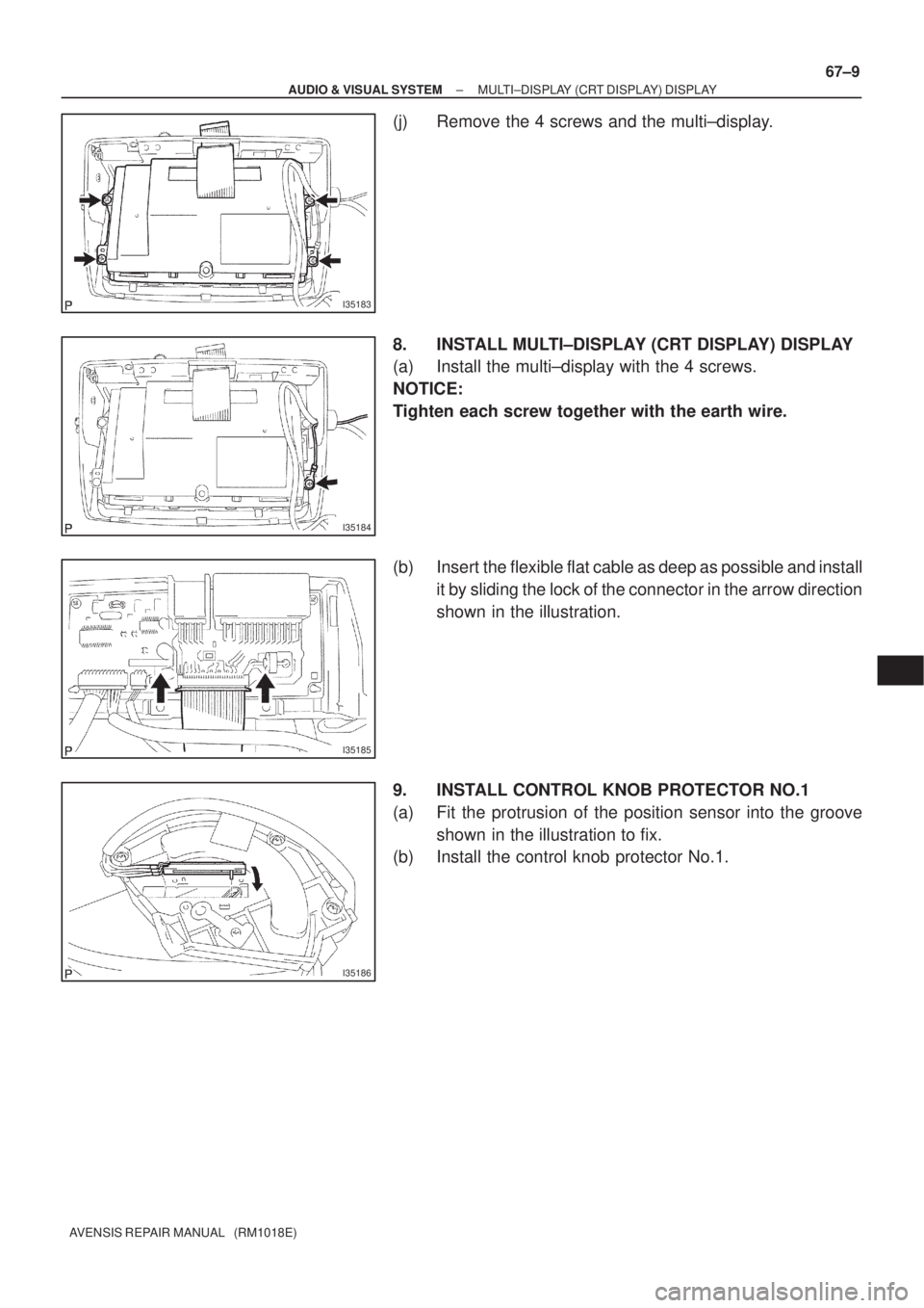
(j) Remove the 4 screws and the multi±display.
8. INSTALL MULTI±DISPLAY (CRT DISPLAY) DISPLAY
(a) Install the multi±display with the 4 screws.
NOTICE:
Tighten each screw together with the earth wire.
(b) Insert the flexible flat cable as deep as possible and install
it by sliding the lock of the connector in the arrow direction
shown in the illustration.
9. INSTALL CONTROL KNOB PROTECTOR NO.1
(a) Fit the protrusion of the position sensor into the groove
shown in the illustration to fix.
(b) Install the control knob protector No.1.
Page 3128 of 5135
670S6±02
I35191
I35165
I35166
±
AUDIO & VISUAL SYSTEM RADIO RECEIVER ASSY
67±5
AVENSIS REPAIR MANUAL (RM1018E)
RADIO RECEIVER ASSY
REPLACEMENT
1.DISCONNECT BATTERY NEGATIVE TERMINAL (See page 60±1)
2.REMOVE INSTRUMENT CLUSTER FINISH PANEL GARNISH NO.2 (See page 71±11)
3.REMOVE INSTRUMENT PANEL REGISTER ASSY CTR (See page 71±11)
4.REMOVE CONSOLE PANEL SUB±ASSY UPPER (See page 71±11)
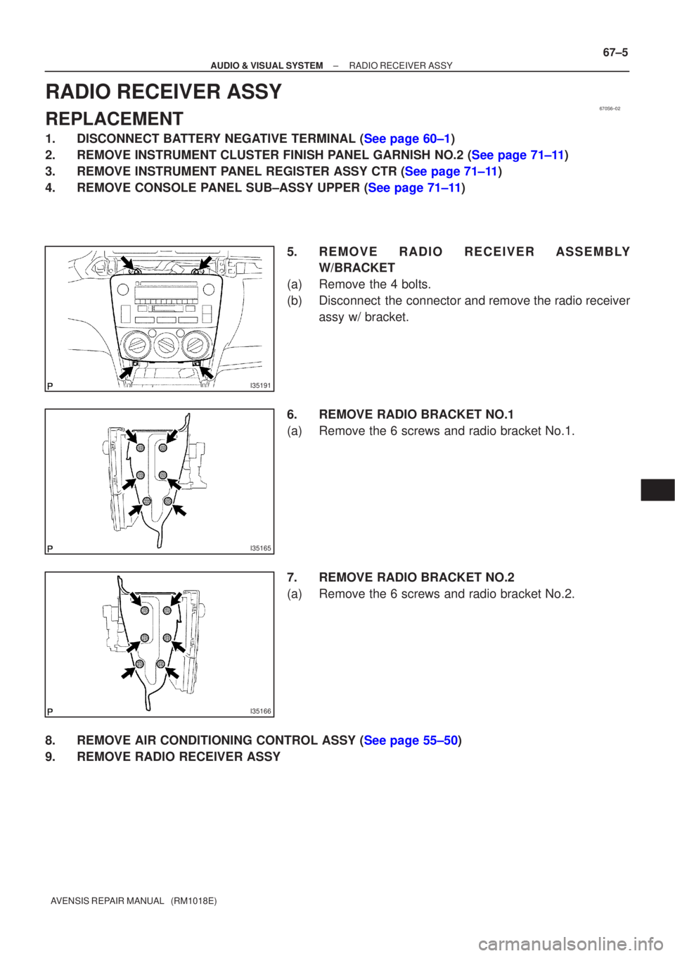
5.REMOVE RADIO RECEIVER ASSEMBLYW/BRACKET
(a)Remove the 4 bolts.
(b)Disconnect the connector and remove the radio receiver assy w/ bracket.
6.REMOVE RADIO BRACKET NO.1
(a)Remove the 6 screws and radio bracket No.1.
7.REMOVE RADIO BRACKET NO.2
(a)Remove the 6 screws and radio bracket No.2.
8.REMOVE AIR CONDITIONING CONTROL ASSY (See page 55±50)
9. REMOVE RADIO RECEIVER ASSY
Page 3129 of 5135
670S5±01
I35223
Instrument Cluster Finish Panel Garnish No.2
Radio Bracket No.2Radio Receiver Assy
Instrument Panel
Register Assy CTR
Air Conditioning Control AssyConsole Panel
Sub±assy Upper
Navigation System:Navigation Computer Cover
Instrument Panel
Support No.3 Instrument Panel
Support No.1Instrument Panel
Support No.2
Door Control Motor
Door Control Switch
Assy (TILT)
Instrument Cluster Finish Panel AssyDoor Control Switch Instrument Cluster Finish
Upper PanelMulti±display Instrument Panel Box
Door CoverRadio Bracket No.1
Instrument Panel
Register Control Gear
Control Knob
Protector No.1
Position Sensor
67±2
± AUDIO & VISUAL SYSTEMAUDIO & VISUAL SYSTEM
AVENSIS REPAIR MANUAL (RM1018E)
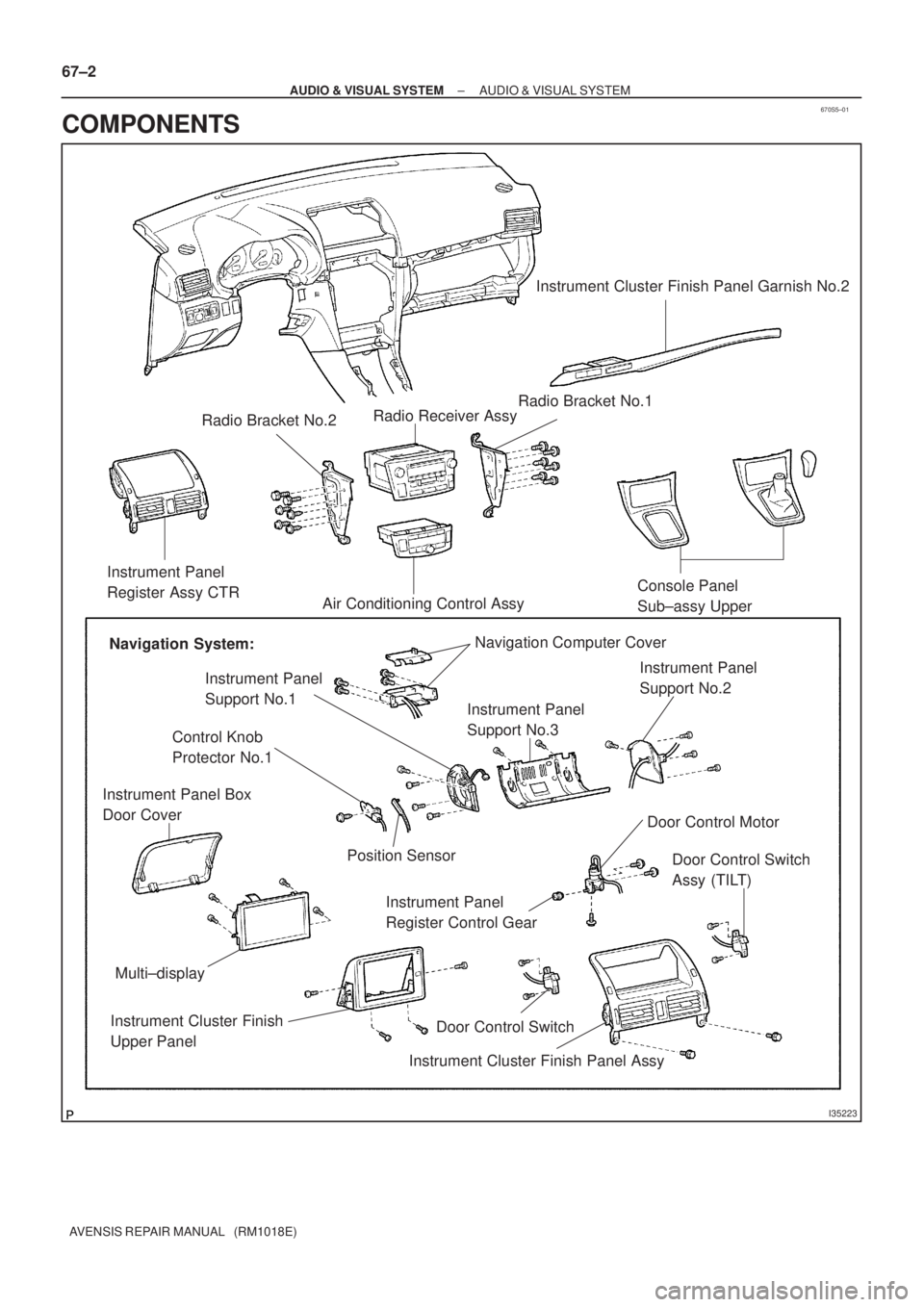
COMPONENTS
Page 3130 of 5135
I35224
Front No.2 Speaker AssyAmplifier Antenna Assy
Front No.1 Speaker
Assy
Rear Speaker AssyNavigation System:
Disc Player Bracket No.2 Rivet
Navigation ECUPower Point Socket Cover
Power Point Socket Assy
Liftback:
Antenna Cord Sub±assy No.3Amplifier Antenna Assy Wagon:
Non±reusable part ��
Disc Player Bracket No.3
Rivet �
Rear No.2 Speaker Assy
Navigation ECU Cover
± AUDIO & VISUAL SYSTEMAUDIO & VISUAL SYSTEM
67±3
AVENSIS REPAIR MANUAL (RM1018E)
Page 3131 of 5135
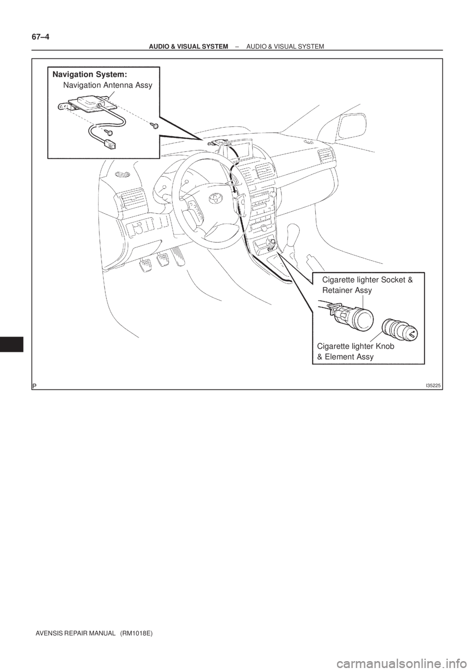
I35225
Navigation System:
Navigation Antenna Assy
Cigarette lighter Socket &
Retainer Assy
Cigarette lighter Knob
& Element Assy 67±4
± AUDIO & VISUAL SYSTEMAUDIO & VISUAL SYSTEM
AVENSIS REPAIR MANUAL (RM1018E)
Page 3132 of 5135
670S4±01
± AUDIO & VISUAL SYSTEMAUDIO & VISUAL SYSTEM
67±1
AVENSIS REPAIR MANUAL (RM1018E)
AUDIO & VISUAL SYSTEM
PRECAUTION
1. OBSERVE HANDLING AND OPERATIONAL PRECAUTIONS
(a) Please explain to the customer that when the negative terminal is disconnected from the battery, the
channel information memory of the AM/FM broadcast stations in the radio receiver is cleared. If neces-
sary, make a note of the recorded channel information before the negative terminal is disconnected,
then reset the information after the negative terminal is reconnected.
(b) The removal/installation of the radio receiver should be performed after all the cassette tapes and au-
dio CDs are ejected from the radio receiver.
HINT:
If the cassette tapes and the audio CDs cannot be ejected due to the malfunction of the radio receiver, do
not try to drag them out by force. Bring the vehicle to the repair plant.
(c) Fasten the earth bolt securely when the antenna cord is removed or installed.
HINT:
Failing to fasten the earth bolt securely causes noise at the time of radio wave reception.
(d) Do not touch the cone paper of the speaker.
Page 3160 of 5135
670SL±01
BE4029
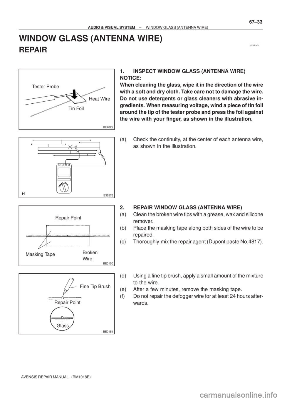
Tester Probe
Tin FoilHeat Wire
E32576
BE0150
Repair Point
Masking TapeBroken
Wire
BE0151
Repair PointFine Tip Brush
Glass
± AUDIO & VISUAL SYSTEMWINDOW GLASS (ANTENNA WIRE)
67±33
AVENSIS REPAIR MANUAL (RM1018E)
WINDOW GLASS (ANTENNA WIRE)
REPAIR
1. INSPECT WINDOW GLASS (ANTENNA WIRE)
NOTICE:
When cleaning the glass, wipe it in the direction of the wire
with a soft and dry cloth. Take care not to damage the wire.
Do not use detergents or glass cleaners with abrasive in-
gredients. When measuring voltage, wind a piece of tin foil
around the tip of the tester probe and press the foil against
the wire with your finger, as shown in the illustration.
(a) Check the continuity, at the center of each antenna wire,
as shown in the illustration.
2. REPAIR WINDOW GLASS (ANTENNA WIRE)
(a) Clean the broken wire tips with a grease, wax and silicone
remover.
(b) Place the masking tape along both sides of the wire to be
repaired.
(c) Thoroughly mix the repair agent (Dupont paste No.4817).
(d) Using a fine tip brush, apply a small amount of the mixture
to the wire.
(e) After a few minutes, remove the masking tape.
(f) Do not repair the defogger wire for at least 24 hours after-
wards.
Page 3161 of 5135
670SK±01
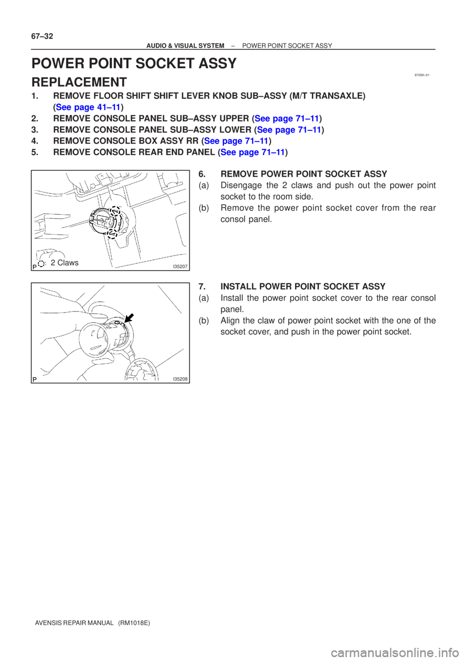
I352072 Claws
I35208
67±32
±
AUDIO & VISUAL SYSTEM POWER POINT SOCKET ASSY
AVENSIS REPAIR MANUAL (RM1018E)
POWER POINT SOCKET ASSY
REPLACEMENT
1. REMOVE FLOOR SHIFT SHIFT LEVER KNOB SUB±ASSY (M/T TRANSAXLE) (See page 41±11)
2.REMOVE CONSOLE PANEL SUB±ASSY UPPER (See page 71±11)
3.REMOVE CONSOLE PANEL SUB±ASSY LOWER (See page 71±11)
4.REMOVE CONSOLE BOX ASSY RR (See page 71±11)
5.REMOVE CONSOLE REAR END PANEL (See page 71±11)
6. REMOVE POWER POINT SOCKET ASSY
(a) Disengage the 2 claws and push out the power pointsocket to the room side.
(b) Remove the power point socket cover from the rear consol panel.
7. INSTALL POWER POINT SOCKET ASSY
(a) Install the power point socket cover to the rear consol panel.
(b) Align the claw of power point socket with the one of the socket cover, and push in the power point socket.