Page 4114 of 5135

05−1 4
−
DIAGNOSTICS SFI SYSTEM (2AZ−FSE)
AVENSIS Supplement (RM 1045E)
Symbols (Terminals No.)
STD Voltage
Condition
Terminal Description
Wiring Color
OC 1+(E 11−1 6)
− OC 1−(E11−1 5)W−G −Y−BCamshaft timing oil con-
trol valve (OCV)Ignition switch ONPulse generation
(See page 05 −41)
EVP 1(E 13− 34) −E0 1(E 13− 7)W −G −W −BVSV for EVAPIgnition switch ON9to 14V
SCV (E 13− 5) −E1 (E 11−1 )L− B −BRVSV for IACVIgnition switch ON9to 14V
PIM (E 13− 33) −E2 (E 13− 28)G −W −BRVacuum sensorIgnition switch ON3.3 to 3.9 V
PIM (E 13− 33) −E2 (E 13− 28)G −W −BRVacuum sensorApply vacuum of 26.7 kPa (200
mmHg, 7.9 in.Hg)2.6 to 3.0 V
PB (E 13− 26) −E2 (E 13− 28)Y −BRBrake booster pressure
sensorIgnition switch ON3.3 to 3.9 V
PB (E 13− 26) −E2 (E 13− 28)Y −BRBrake booster pressure
sensorApply vacuum of 26.7 kPa (200
mmHg, 7.9 in.Hg)2.6 to 3.0 V
PR (E 13− 23) −E2 (E 13− 28)Y −G −BRFuel pressure sensorIdling2.1 to 3.2 V
FP+ (E 12− 6) −E0 1(E 13− 7)
FP −(E 12− 3) −E0 1(E 13− 7)R −BR
G −BRSpill valveIdlingPulse generation
(See page 05 −207)
STA (E 13−1 7)−E1 (E 11−1 )B−Y −BRStarter signalShift position in neutral, Ignition
switch START6.0 V or more
STP (E 10−1 9)−E1 (E 11−1 )G−W −BRStop lamp switchBrake pedal depressed9to 14V
STP (E 10−1 9)−E1 (E 11−1 )G−W −BRStop lamp switchBrake pedal releasedBelow 1.5 V
ST 1− (E10−1 2)−E1 (E 11−1 )G−W −BRStop lamp switchIgnition switch ON, Brake pedal de-
pressedBelow 1.5 V
ST 1− (E10−1 2)−E1 (E 11−1 )G−W −BRStop lamp switchIgnition switch ON, Brake pedal re-
leased7.5 to 14V
W (E9 −11)− E1 (E 11−1 )W−W −BCHK ENGIdling9to 14V
W (E9 −11)− E1 (E 11−1 )W−W −BCHK ENGIgnition switch ONBelow 3.0 V
ELS (E9 −12)−E1 (E 11−1 )G−BRElectric loadTaillight switch ON, Defogger switch
ON7.5 to 14V
ELS (E9 −12)−E1 (E 11−1 )G−BRElectric loadTaillight switch OFF, Defogger
switch OFF0to 1.5 V
TACH (E9 −5) −E1 (E 11−1 )GR−R −BREngine speedIdlingPulse generation
SPD (E 10−1 7)−E1 (E 11−1 )V−W −W −BSpeed signal from com-
bination meterIgnition switch ON, Rotate driving
wheel slowly4.5 to 5.5 V
TC (E9 −20) −E1 (E 11−1 )W−L −BRTerminal TC of DLC 3Ignition switch ON9to 14V
SIL (E9 −18)−E1 (E 11−1 )W−G −BRTerminal SIL of DLC3Connect the hand −held tester to
DLC3Pulse generation
PSW (E 11−10)−E1 (E 11−1 )G−BRPower steering oil pres-
sure switchWhile turning the steering wheelBelow 1.5 V
F/PS (E9 −14)−E1 (E 11−1 )LG−B −BRAirbag sensor assemblyIgnition switch ONBelow 1.5 V
Page 4115 of 5135

05CDX−02
05 −1 0
−
DIAGNOSTICS SFI SYSTEM (2AZ−FSE)
AVENSIS Supplement (RM 1045E)
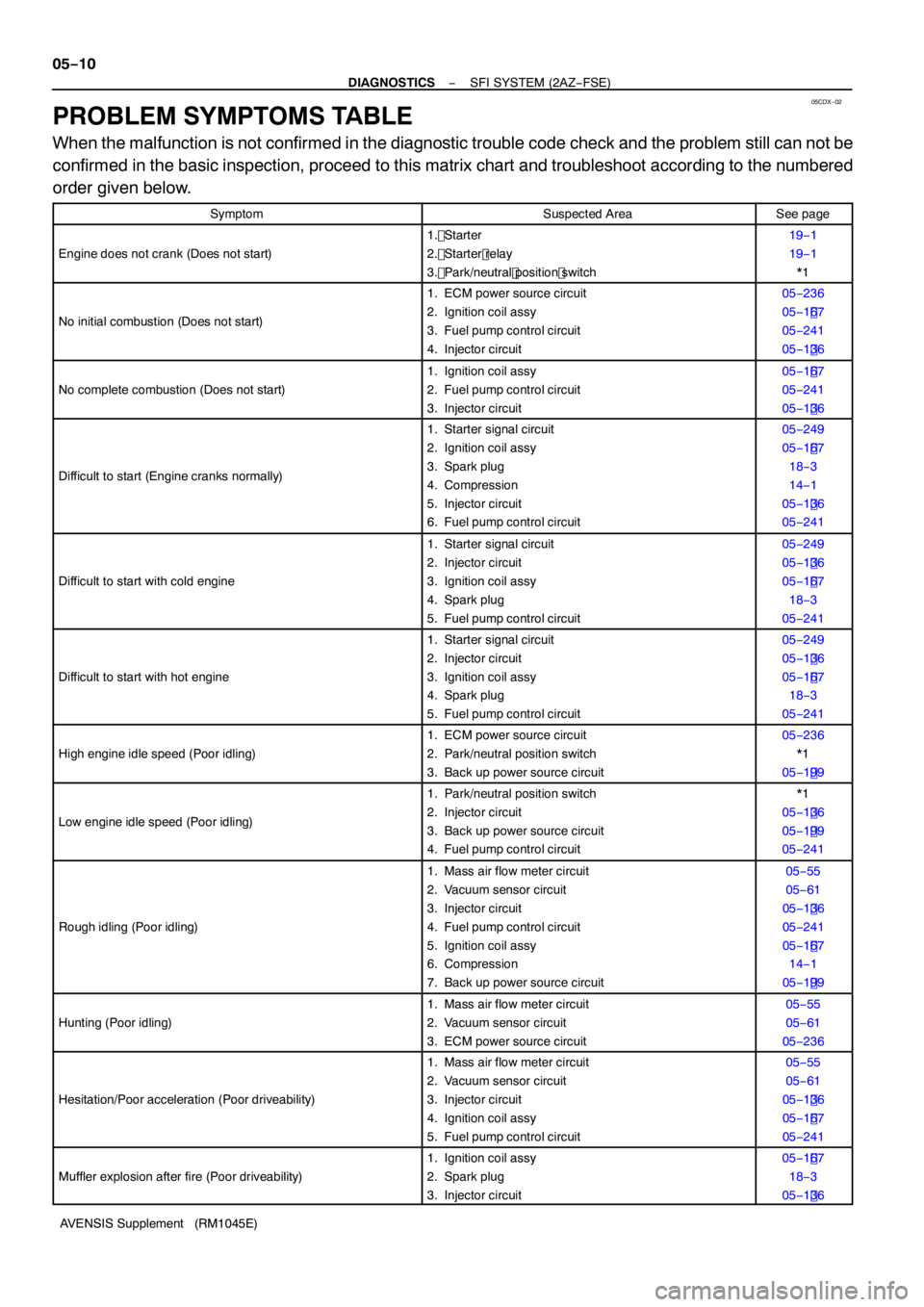
PROBLEM SYMPTOMS TABLE
When the malfunction is not confirmed in the diagnostic trouble code check and the problem still can not be
confirmed in the basic inspection, proceed to this matrix chart and troubleshoot according to the numbered
order given below.
SymptomSuspected AreaSee page
Engine does not crank (Does not start)
1. Starter
2. Starter relay
3. Park/neutral position switch19 −1
1 9 −1
* 1
No initial combustion (Does not start)
1 . ECM power source circuit
2. Ignition coil assy
3. Fuel pump control circuit
4. Injector circuit05 −236
05 −1 67
05 −24 1
05 −1 36
No complete combustion (Does not start)
1. Ignition coil assy
2. Fuel pump control circuit
3. Injector circuit05 −1 67
05 −24 1
05 −1 36
Difficult to start (Engine cranks normally)
1. Starter signal circuit
2. Ignition coil assy
3. Spark plug
4. Compression
5. Injector circuit
6. Fuel pump control circuit05 −249
05 −1 67
1 8 − 3
1 4 −1
05 −1 36
05 −24 1
Difficult to start with cold engine
1. Starter signal circuit
2. Injector circuit
3. Ignition coil assy
4. Spark plug
5. Fuel pump control circuit05 −249
05 −1 36
05 −1 67
1 8 − 3
05 −24 1
Difficult to start with hot engine
1. Starter signal circuit
2. Injector circuit
3. Ignition coil assy
4. Spark plug
5. Fuel pump control circuit05 −249
05 −1 36
05 −1 67
1 8 − 3
05 −24 1
High engine idle speed (Poor idling)
1. ECM power source circuit
2. Park/neutral position switch
3. Back up power source circuit05 −236
* 1
05 −1 99
Low engine idle speed (Poor idling)
1. Park/neutral position switch
2. Injector circuit
3. Back up power source circuit
4. Fuel pump control circuit* 1
05 −1 36
05 −1 99
05 −24 1
Rough idling (Poor idling)
1. Mass air flow meter circuit
2. Vacuum sensor circuit
3. Injector circuit
4. Fuel pump control circuit
5. Ignition coil assy
6. Compression
7. Back up power source circuit05 −55
05 −61
05 −1 36
05 −24 1
05 −1 67
1 4 −1
05 −1 99
Hunting (Poor idling)
1. Mass air flow meter circuit
2. Vacuum sensor circuit
3. ECM power source circuit05 −55
05 −61
05 −236
Hesitation/Poor acceleration (Poor driveability)
1. Mass air flow meter circuit
2. Vacuum sensor circuit
3. Injector circuit
4. Ignition coil assy
5. Fuel pump control circuit05 −55
05 −61
05 −1 36
05 −1 67
05 −24 1
Muffler explosion after fire (Poor driveability)
1. Ignition coil assy
2. Spark plug
3. Injector circuit05 −1 67
1 8 − 3
05 −1 36
Page 4118 of 5135
−
DIAGNOSTICS SFI SYSTEM (2AZ−FSE)
05 −9
AVENSIS Supplement (RM 1045E)
6 CHECK IGNITION TIMING (See page 14−1 )
NG PROCEED TO PAGE 18−1 AND CONTINUE TO
TROUBLESHOOT
OK
PROCEED TO PROBLEM SYMPTOMS TABLE ON PAGE 05 −1 0
7 CHECK FUEL PRESSURE (See page 11− 4)
NG PROCEED TO PAGE 11−1 AND CONTINUE TO
TROUBLESHOOT
OK
8 CHECK FOR SPARK (See page 18−1 )
NG PROCEED TO PAGE 18−1 AND CONTINUE TO
TROUBLESHOOT
OK
PROCEED TO PROBLEM SYMPTOMS TABLE ON PAGE 05 −1 0
Page 4124 of 5135

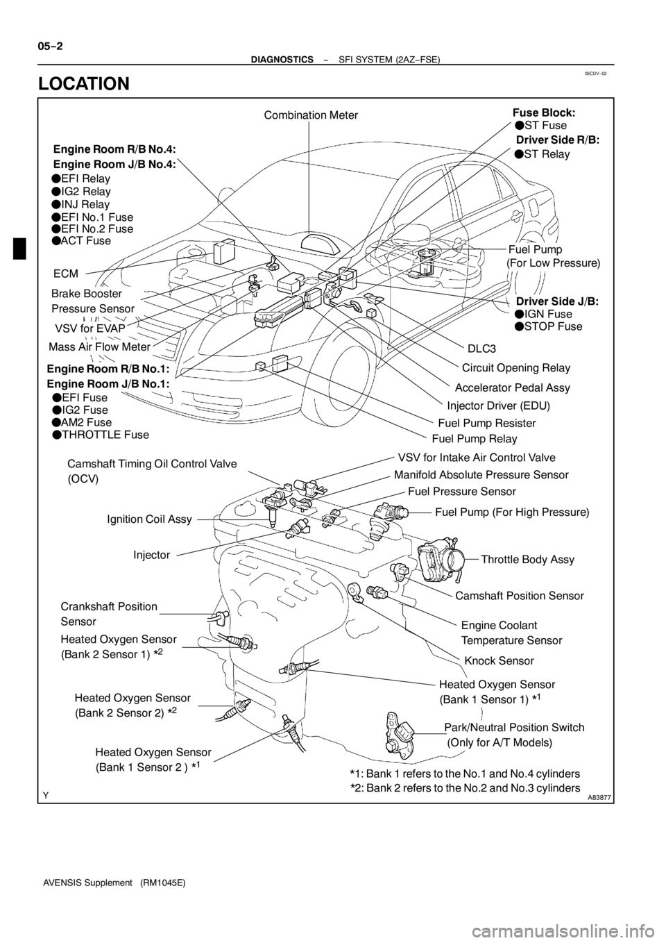
05CDV−02
A83877
Ignition Coil Assy
Camshaft Position Sensor
VSV for EVAP
Combination Meter
DLC3
VSV for Intake Air Control Valve
Fuel Pump
ECM
Knock Sensor Camshaft Timing Oil Control Valve
(OCV)
Injector
Crankshaft Position
Sensor
Park/Neutral Position Switch
(Only for A/T Models)Engine Coolant
Temperature Sensor
Mass Air Flow Meter
Throttle Body Assy
Accelerator Pedal Assy
Heated Oxygen Sensor
(Bank 2 Sensor 2) *
2
Circuit Opening Relay
Heated Oxygen Sensor
(Bank1Sensor 2 ) *
1
Heated Oxygen Sensor
(Bank 2 Sensor1)*
2
Heated Oxygen Sensor
(Bank1Sensor1)*
1
Manifold Absolute Pressure Sensor
Fuel Pump (For High Pressure)
Injector Driver (EDU)
Brake Booster
Pressure Sensor
Fuel Pressure Sensor
(For Low Pressure)
FEFI Fuse
FIG2 Fuse
FAM2 Fuse
FTHROTTLE Fuse
FEFI Relay
FIG2 Relay
FINJ Relay
FEFI No.1Fuse
FEFI No.2 Fuse
FACT Fuse
FST Fuse
FIGN Fuse
FSTOP Fuse
FST Relay
Fuel Pump RelayFuel Pump Resister
*1: Bank1refers to the No.1and No.4 cylinders
*2: Bank 2 refers to the No.2 and No.3 cylinders
Engine Room R/B No.4:
Engine Room J/B No.4:Fuse Block:
Engine Room R/B No.1:
Engine Room J/B No.1:
Driver Side R/B:
Driver Side J/B: 05−2
− DIAGNOSTICSSFI SYSTEM (2AZ−FSE)
AVENSIS Supplement (RM1045E)
LOCATION
Page 4127 of 5135
054JE−09
A85347
Mass Air Flow Meter
DLC3
Accelerator Pedal Assy
(Accelerator Pedal
Position Sensor)
EDUECM
Engine Room R/B No. 1:
FEDU Relay
FEDU Fuse
Glow Plug Relay
Camshaft Position SensorInjector
Crankshaft Position Sensor
Engine Coolant Temperature Sensor Fuel Pressure Sensor
Fuse Block
FST Fuse
Driver Side J/B
FGAUGE Fuse
FSTOP Fuse
Driver Side R/B
FST Relay
E−VRV Pressure Discharge Valve Glow Plug
Exhaust Gas Temperature
Sensor (on down stream)Intake Air Temperature Sensor
EGR Valve
Turbo Pressure Sensor
Intake Shutter (Throttle Valve)
Suction Control Valve
Fuel Temperature Sensor
Supply Pump Exhaust Gas Temperature
Sensor (on up stream)
Exhaust Fuel Addition Injector
A/F Sensor
Engine Room R/B No. 3:
FGLOW Fuse
EGR Valve
Position Sensor
Intake Shutter
(Throttle Valve)
Position Sensor
Differential Pressure Sensor 05−254
− DIAGNOSTICSECD SYSTEM (1CD−FTV)(From September, 2003)
AVENSIS Supplement (RM1045E)
LOCATION
Page 4128 of 5135

05DVP−02
A8570 1
Sample:
Injector
Compensation Code
−
DIAGNOSTICS ECD SYSTEM (1CD −FTV)(From September, 2003)
05 −253
AVENSIS Supplement (RM 1045E)
ECD SYSTEM ( 1CD −FTV)(From September, 2003)
PRECAUTION
1. INJECTOR COMPENSATION CODE
(a) Since each injector has its own fuel injection characteris- tic, the ECM compensates this by slightly modifying injec-
tion duration in order to optimize fuel injection volume.
Compensating data for the optimum injection volume, in
the form of a 30 −digit −alphanumeric value, has been im-
printed on the head portion of each injector as the injector
compensation code.
(b) The injector compensation code will be required to regis- ter to the ECM when replacing the injectors or the ECM
(see page 05 −277).
(c) If an incorrect injector compensation code was registered
to the ECM, it may rattle the engine assembly or the en-
gine idling may become rough. In addition, it may become
a cause of engine failure or shorten the life of the engine.
2. DIFFICULT TO ENGINE START, ENGINE STALL OR BLACK SMOKE
(a) If the customer ’s problem description is applicable to one of the following problems, refer to the troubleshooting on
the pages shown below:
(1 ) Engine start difficulties, or engine stall, see page
05−502.
(2) Black smoke, see page 05 −512.
Page 4131 of 5135

−
DIAGNOSTICS SFI SYSTEM (2AZ−FSE)
05 −249
AVENSIS Supplement (RM 1045E)
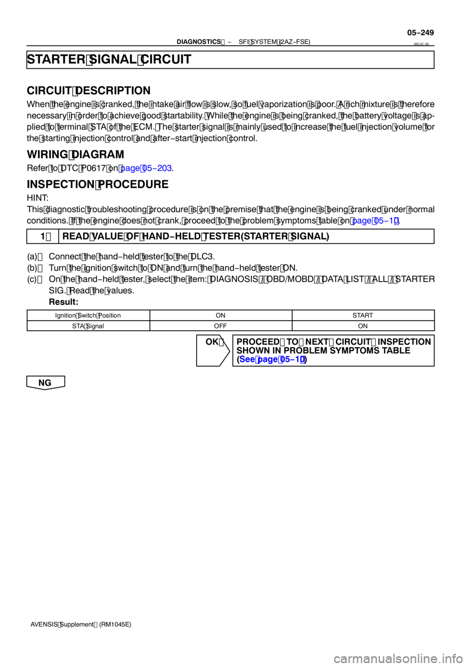
STARTER SIGNAL CIRCUIT
CIRCUIT DESCRIPTION
When the engine is cranked, the intake air flow is slow, so fuel vaporization is poor. A rich mixture is therefore
necessary in order to achieve good startability. While the engine is being cranked, the battery voltage is ap-
plied to terminal STA of the ECM. The starter signal is mainly used to increase the fuel injection volume for
the starting injection control and after −start injection control.
WIRING DIAGRAM
Refer to DTC P06 17 on page 05 −203.
INSPECTION PROCEDURE
HINT:
This diagnostic troubleshooting procedure is on the premise that the engine is being cranked under normal
conditions. If the engine does not crank, proceed to the problem symptoms table on page 05 −1 0.
1 READ VALUE OF HAND −HELD TESTER(STARTER SIGNAL)
(a) Connect the hand −held tester to the DLC3.
(b) Turn the ignition switch to ON and turn the hand −held tester ON.
(c) On the hand −held tester, select the item: DIAGNOSIS / OBD/MOBD / DATA LIST / ALL / STARTER
SIG. Read the values.
Result:
Ignition Switch PositionONSTART
STA SignalOFFON
OK PROCEED TO NEXT CIRCUIT INSPECTION SHOWN IN PROBLEM SYMPTOMS TABLE
(See page 05 −1 0)
NG
05CJC −02
Page 4133 of 5135

1
2
3
4
A93906
−
DIAGNOSTICS SFI SYSTEM (2AZ−FSE)
05 −24 1
AVENSIS Supplement (RM1045E)
FUEL PUMP CONTROL CIRCUIT
CIRCUIT DESCRIPTION
Refer to DTC P0230 on page 05 −141.
WIRING DIAGRAM
Refer to DTC P0230 on page 05 −141.
INSPECTION PROCEDURE
1 CHECK FUEL PUMP OPERATION (See page 11− 4)
(a) Check if there is pressure in the fuel inlet hose.
HINT:
If there is fuel pressure, you will hear the sound of fuel flowing.
OK Go to step 9
NG
2 PERFORM ACTIVE TEST BY HAND −HELD TESTER(OPERATION OF CIRCUIT
OPENING RELAY)
(a) Connect the hand −held tester to the DLC3.
(b) Start the engine and warm it up.
(c) Turn the ignition switch to ON.
(d) Select the item: DIAGNOSIS / OBD/MOBD / ACTIVE TEST / FUEL PUMP/SPD.
(e) Check the relay operation when it is operated by the hand −held tester.
Standard: Operating sound can be heard from the relay.
OK Go to step 4
NG
3 INSPECT RADIATOR FAN RELAY
(a) Remove the R21 radiator fan relay.
(b) Check for continuity in the radiator fan relay relay. Standard:
Tester ConnectionSpecified Condition
1−2Continuity
3−4Continuity
1−2No Continuity
(Apply battery voltage to terminals 3 and 4)
(c) Reinstall the radiator fan relay relay.
NG REPLACE FUEL PUMP RELAY
OK
05HIS −01