Page 2916 of 5135
550ZI±01
I35437
Connector ºBº Wire harness side:
Connector ºAº
I36091
Connector ºBº From back side:
Connector ºAº 55±22
± HEATER & AIR CONDITIONERHOT GAS TYPE POWER HEATER SYSTEM
AVENSIS REPAIR MANUAL (RM1018E)
HOT GAS TYPE POWER HEATER SYSTEM
ON±VEHICLE INSPECTION
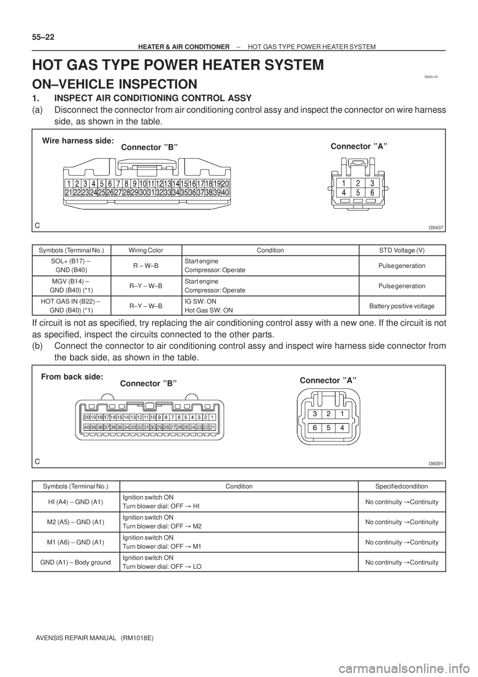
1. INSPECT AIR CONDITIONING CONTROL ASSY
(a) Disconnect the connector from air conditioning control assy and inspect the connector on wire harness
side, as shown in the table.
Symbols (Terminal No.)Wiring ColorConditionSTD Voltage (V)
SOL+ (B17) ±
GND (B40)R ± W±BStart engine
Compressor: OperatePulse generation
MGV (B14) ±
GND (B40) (*1)R±Y ± W±BStart engine
Compressor: OperatePulse generation
HOT GAS IN (B22) ±
GND (B40) (*1)R±Y ± W±BIG SW: ON
Hot Gas SW: ONBattery positive voltage
If circuit is not as specified, try replacing the air conditioning control assy with a new one. If the circuit is not
as specified, inspect the circuits connected to the other parts.
(b) Connect the connector to air conditioning control assy and inspect wire harness side connector from
the back side, as shown in the table.
Symbols (Terminal No.)ConditionSpecified condition
HI (A4) ± GND (A1)Ignition switch ON
Turn blower dial: OFF � HINo continuity �Continuity
M2 (A5) ± GND (A1)Ignition switch ON
Turn blower dial: OFF � M2No continuity �Continuity
M1 (A6) ± GND (A1)Ignition switch ON
Turn blower dial: OFF � M1No continuity �Continuity
GND (A1) ± Body groundIgnition switch ON
Turn blower dial: OFF � LONo continuity �Continuity
Page 2918 of 5135
I32394
1
2
I32395
Wire harness side: 55±20
± HEATER & AIR CONDITIONERCOMBUSTION TYPE POWER HEATER SYSTEM
AVENSIS REPAIR MANUAL (RM1018E)
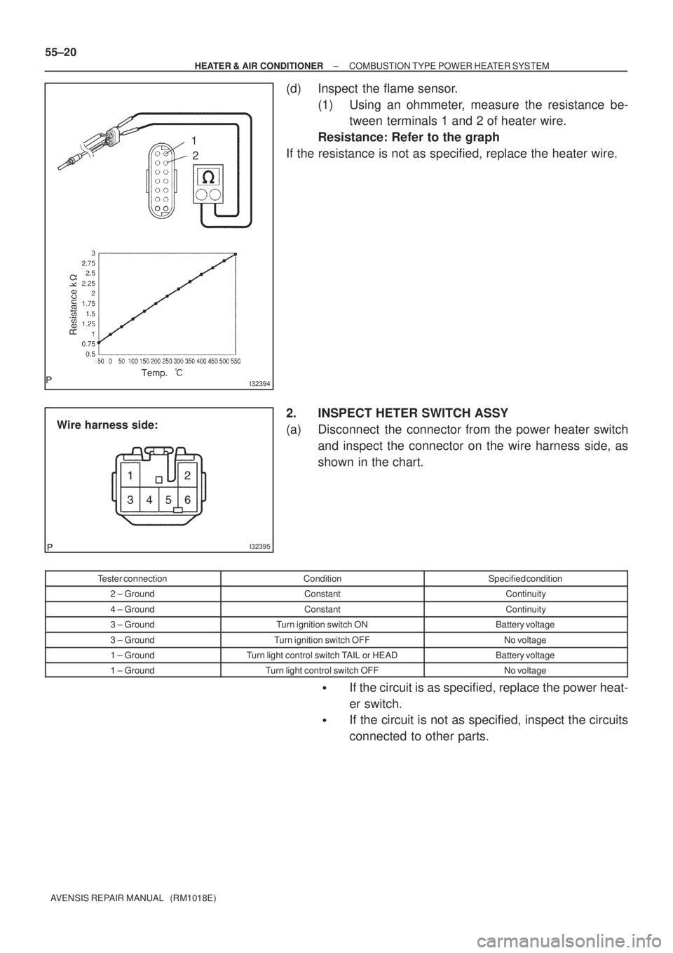
(d) Inspect the flame sensor.
(1) Using an ohmmeter, measure the resistance be-
tween terminals 1 and 2 of heater wire.
Resistance: Refer to the graph
If the resistance is not as specified, replace the heater wire.
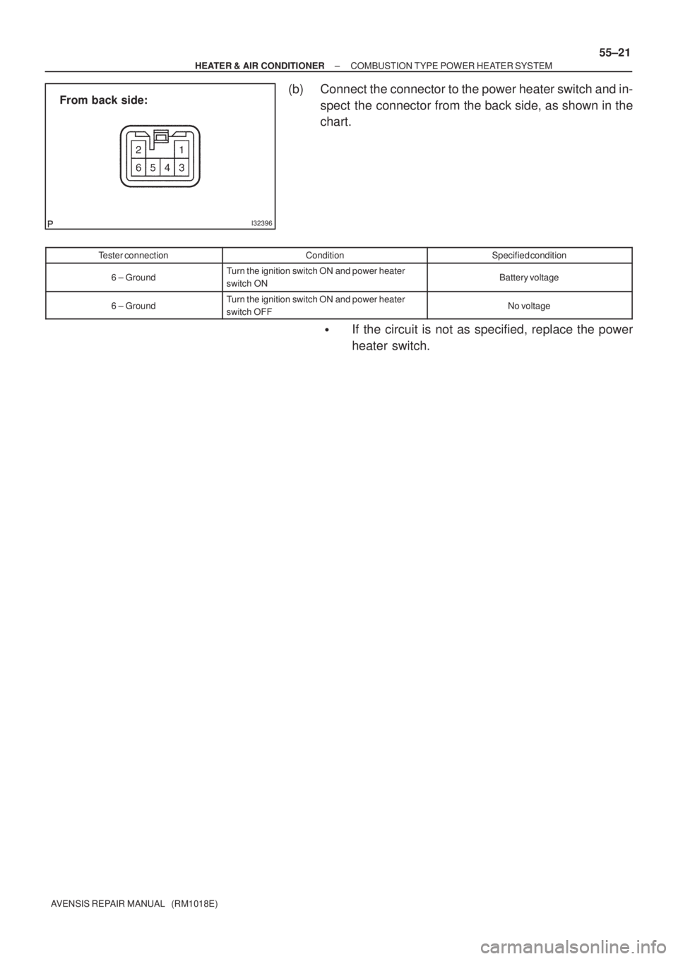
2. INSPECT HETER SWITCH ASSY
(a) Disconnect the connector from the power heater switch
and inspect the connector on the wire harness side, as
shown in the chart.
Tester connectionConditionSpecified condition
2 ± GroundConstantContinuity
4 ± GroundConstantContinuity
3 ± GroundTurn ignition switch ONBattery voltage
3 ± GroundTurn ignition switch OFFNo voltage
1 ± GroundTurn light control switch TAIL or HEADBattery voltage
1 ± GroundTurn light control switch OFFNo voltage
�If the circuit is as specified, replace the power heat-
er switch.
�If the circuit is not as specified, inspect the circuits
connected to other parts.
Page 2919 of 5135
I32396
From back side:
± HEATER & AIR CONDITIONERCOMBUSTION TYPE POWER HEATER SYSTEM
55±21
AVENSIS REPAIR MANUAL (RM1018E)
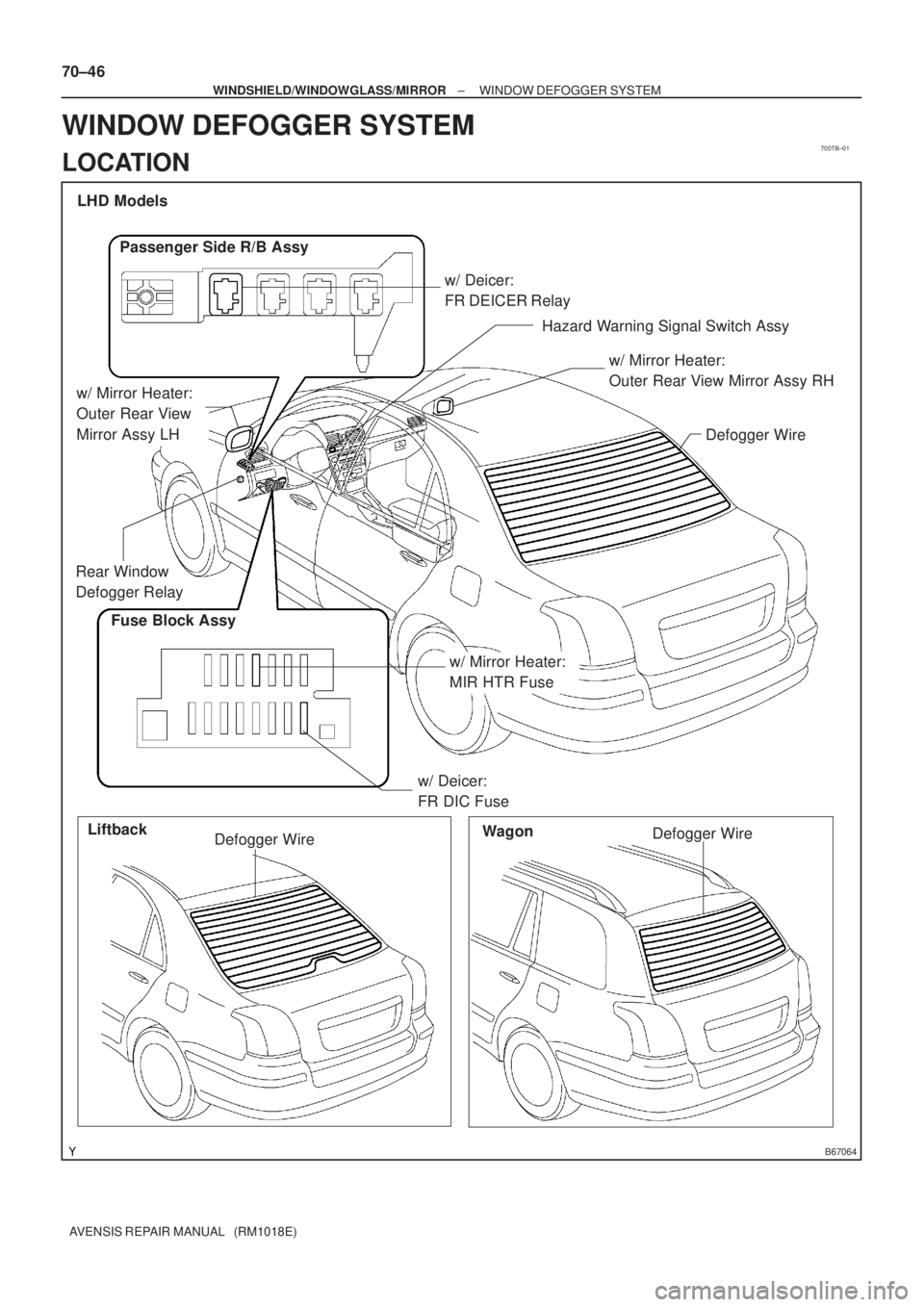
(b) Connect the connector to the power heater switch and in-
spect the connector from the back side, as shown in the
chart.
Tester connectionConditionSpecified condition
6 ± GroundTurn the ignition switch ON and power heater
switch ONBattery voltage
6 ± GroundTurn the ignition switch ON and power heater
switch OFFNo voltage
�If the circuit is not as specified, replace the power
heater switch.
Page 2932 of 5135
550RQ±02
55±6
±
HEATER & AIR CONDITIONER AIR CONDITIONING SYSTEM
AVENSIS REPAIR MANUAL (RM1018E)
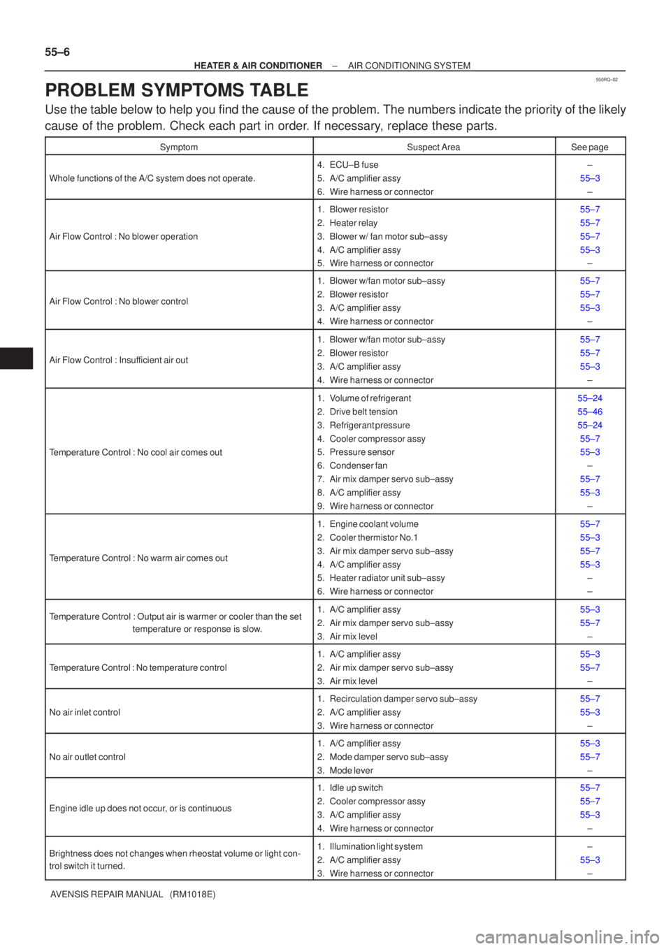
PROBLEM SYMPTOMS TABLE
Use the table below to help you find the cause of the problem. The numbers \
indicate the priority of the likely
cause of the problem. Check each part in order. If necessary, replace these parts.
SymptomSuspect AreaSee page
Whole functions of the A/C system does not operate.
4. ECU±B fuse
5. A/C amplifier assy
6. Wire harness or connector±
55±3 ±
Air Flow Control : No blower operation
1. Blower resistor
2. Heater relay
3. Blower w/ fan motor sub±assy
4. A/C amplifier assy
5. Wire harness or connector55±7
55±7
55±7
55±3±
Air Flow Control : No blower control
1. Blower w/fan motor sub±assy
2. Blower resistor
3. A/C amplifier assy
4. Wire harness or connector55±7
55±7
55±3
±
Air Flow Control : Insufficient air out
1. Blower w/fan motor sub±assy
2. Blower resistor
3. A/C amplifier assy
4. Wire harness or connector55±7
55±7
55±3±
Temperature Control : No cool air comes out
1. Volume of refrigerant
2. Drive belt tension
3. Refrigerant pressure
4. Cooler compressor assy
5. Pressure sensor
6. Condenser fan
7. Air mix damper servo sub±assy
8. A/C amplifier assy
9. Wire harness or connector55±24
55±46
55±2455±7
55±3 ±
55±7
55±3 ±
Temperature Control : No warm air comes out
1. Engine coolant volume
2. Cooler thermistor No.1
3. Air mix damper servo sub±assy
4. A/C amplifier assy
5. Heater radiator unit sub±assy
6. Wire harness or connector55±7
55±3
55±7
55±3±
±
Temperature Control : Output air is warmer or cooler than the set
temperature or response is slow.1. A/C amplifier assy
2. Air mix damper servo sub±assy
3. Air mix level55±3
55±7
±
Temperature Control : No temperature control
1. A/C amplifier assy
2. Air mix damper servo sub±assy
3. Air mix level55±3
55±7±
No air inlet control
1. Recirculation damper servo sub±assy
2. A/C amplifier assy
3. Wire harness or connector55±7
55±3±
No air outlet control
1. A/C amplifier assy
2. Mode damper servo sub±assy
3. Mode lever55±3
55±7±
Engine idle up does not occur, or is continuous
1. Idle up switch
2. Cooler compressor assy
3. A/C amplifier assy
4. Wire harness or connector55±7
55±7
55±3±
Brightness does not changes when rheostat volume or light con-
trol switch it turned.1. Illumination light system
2. A/C amplifier assy
3. Wire harness or connector±
55±3 ±
Page 3171 of 5135
700TB±01
B67064
LHD Models
Defogger Wire
Liftback
Wagon
Defogger Wire
Defogger Wire
Hazard Warning Signal Switch Assy w/ Deicer:
FR DEICER Relay
Fuse Block Assy
w/ Deicer:
FR DIC Fuse
w/ Mirror Heater:
MIR HTR Fuse
Passenger Side R/B Assy
w/ Mirror Heater:
Outer Rear View Mirror Assy RH
w/ Mirror Heater:
Outer Rear View
Mirror Assy LH
Rear Window
Defogger Relay
70±46
± WINDSHIELD/WINDOWGLASS/MIRRORWINDOW DEFOGGER SYSTEM
AVENSIS REPAIR MANUAL (RM1018E)
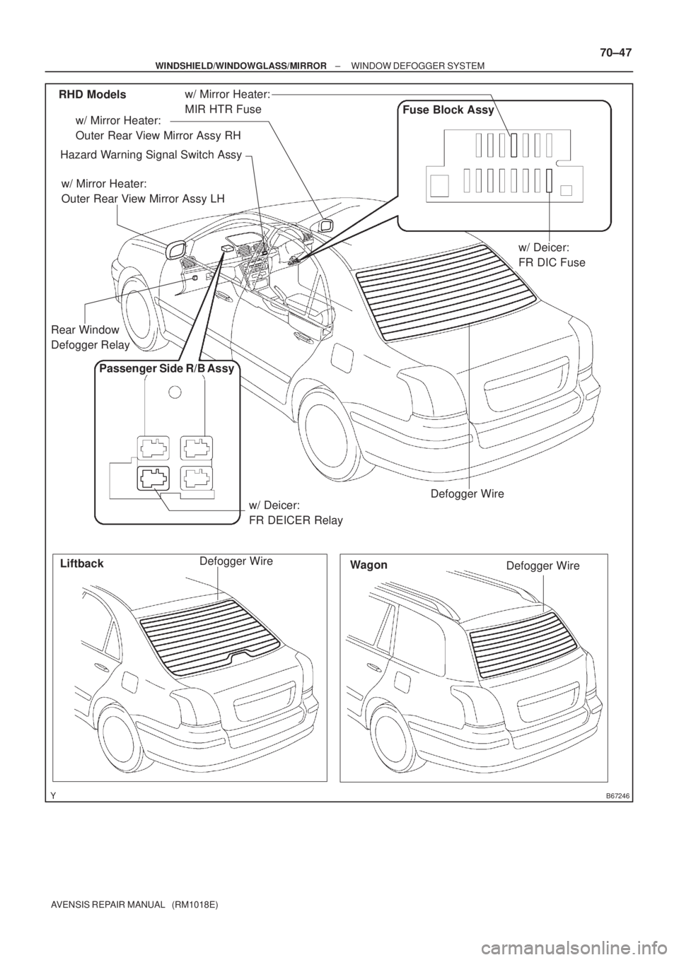
WINDOW DEFOGGER SYSTEM
LOCATION
Page 3172 of 5135
B67246
RHD Models
Defogger Wire
Liftback
Wagon
Defogger Wire Defogger Wire
Hazard Warning Signal Switch Assy
Passenger Side R/B Assy
w/ Deicer:
FR DEICER Relay
Fuse Block Assy
w/ Deicer:
FR DIC Fuse w/ Mirror Heater:
Outer Rear View Mirror Assy RH
w/ Mirror Heater:
Outer Rear View Mirror Assy LH
w/ Mirror Heater:
MIR HTR Fuse
Rear Window
Defogger Relay
± WINDSHIELD/WINDOWGLASS/MIRRORWINDOW DEFOGGER SYSTEM
70±47
AVENSIS REPAIR MANUAL (RM1018E)
Page 3233 of 5135
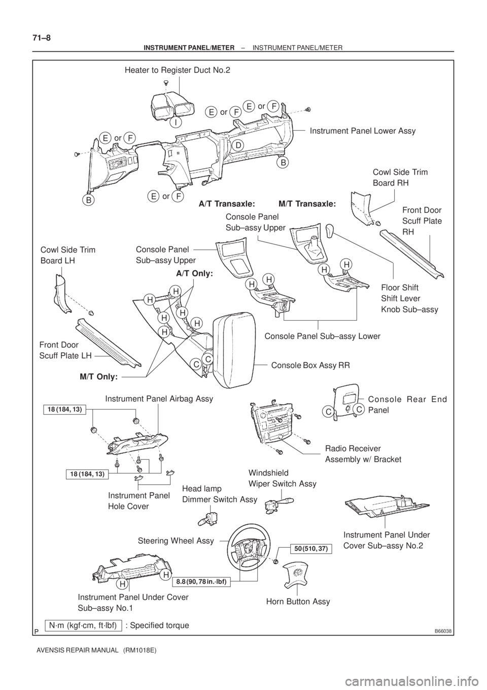
B66038
Heater to Register Duct No.2
Instrument Panel Lower Assy
Cowl Side Trim
Board RH
Front Door
Scuff Plate
RH
Floor Shift
Shift Lever
Knob Sub±assy Console Panel
Sub±assy Upper
Console Panel Sub±assy Lower
Console Box Assy RR Front Door
Scuff Plate LHCowl Side Trim
Board LH
Instrument Panel Airbag Assy
Console Rear End
Panel
Radio Receiver
Assembly w/ Bracket
Windshield
Wiper Switch Assy
Instrument Panel
Hole CoverHead lamp
Dimmer Switch Assy
Instrument Panel Under
Cover Sub±assy No.2
Horn Button Assy Steering Wheel Assy
Instrument Panel Under Cover
Sub±assy No.1
H
N´m (kgf´cm, ft´lbf) : Specified torqueM/T Transaxle: A/T Transaxle:
A/T Only:
M/T Only:
50 (510, 37)
8.8 (90, 78 in.´lbf)
orEF
D
B
Bor
EF
I
or
EF
or
EF
H
HH
H
H
HH
H
H
CC
CC
H
HConsole Panel
Sub±assy Upper
18 (184, 13)
18 (184, 13)
71±8
± INSTRUMENT PANEL/METERINSTRUMENT PANEL/METER
AVENSIS REPAIR MANUAL (RM1018E)
Page 3257 of 5135
700TC±01
±
WINDSHIELD/WINDOWGLASS/MIRROR WINDOW DEFOGGER SYSTEM
70±49
AVENSIS REPAIR MANUAL (RM1018E)
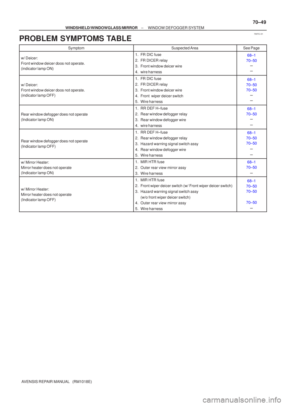
PROBLEM SYMPTOMS TABLE
SymptomSuspected AreaSee Page
w/ Deicer:
Front window deicer doos not operate.
(indicator lamp ON)1. FR DIC fuse
2. FR DICER relay
3. Front window deicer wire
4. wire harness68±1
70±50 �
�
w/ Deicer:
Front window deicer doos not operate.
(indicator lamp OFF)
1. FR DIC fuse
2. FR DICER relay
3. Front window deicer wire
4. Front wiper deicer switch
5. Wire harness68±1
70±50
70±50 �
�
Rear window defogger does not operate
(Indicator lamp ON)
1. RR DEF H±fuse
2. Rear window defogger relay
3. Rear window defogger wire
4. wire harness68±1
70±50 �
�
Rear window defogger does not operate
(Indicator lamp OFF)
1. RR DEF H±fuse
2. Rear window defogger relay
3. Hazard warning signal switch assy
4. Rear window defogger wire
5. Wire harness68±1
70±50
70±50
�
�
w/ Mirror Heater:
Mirror heater does not operate
(Indicator lamp ON)1. MIR HTR fuse
2. Outer rear view mirror assy
3. Wire harness68±1
70±50
�
w/ Mirror Heater:
Mirror heater does not operate
(Indicator lamp OFF)
1. MIR HTR fuse
2. Front wiper deicer switch (w/ Front wiper deicer switch)
3. Hazard warning signal switch assy (w/o front wiper deicer switch)
4. Outer rear view mirror assy
5. Wire harness68±1
70±50
70±50
70±50
�