Page 3577 of 5135

C250 M/T REPAIR MANUAL (RM1020E)
10. REMOVE SELECT SPRING NO.1 SEAT SHAFT SNAP
RING
(a)")
D30556
C80778
C94255
SST
D30557
41±62
± MANUAL TRANSMISSION/TRANSAXLESHIFT & SELECT LEVER SHAFT ASSY (C250)
C250 M/T REPAIR MANUAL (RM1020E)
10. REMOVE SELECT SPRING NO.1 SEAT SHAFT SNAP
RING
(a) Using 2 screwdrivers and a hammer, remove the select
spring No.1 seat shaft snap ring.
NOTICE:
Do not damage the shaft.
11. REMOVE SHIFT & SELECT LEVER SHAFT DUST BOOT
(a) Remove the shift & select lever shaft dust boot from the shift & select lever shaft.
12. REMOVE CONTROL SHAFT COVER OIL SEAL
(a) Using a screwdriver remove the control shaft cover oil
seal from the control shaft cover.
13. INSTALL CONTROL SHAFT COVER OIL SEAL
(a) Using SST and a hammer, install the new control shaft
cover oil seal to the control shaft cover.
SST 09950±60010 (09951±00220), 09950±70010
(09951±07100)
Drive in depth:
0.2 ± 1.2 mm (0.079 ± 0.0472 in.)
(b) Coat the control shaft cover oil seal with MP grease.
14. INSTALL SHIFT & SELECT LEVER SHAFT DUST
BOOT
(a) Coat the shift & select lever shaft dust boot with MP
grease.
(b) Install the shift & select lever shaft dust boot to the shift
& select lever shaft.
HINT:
Install the boot with the projection up and the hole side down.
Page 3580 of 5135
410DI±01
������������
D30695
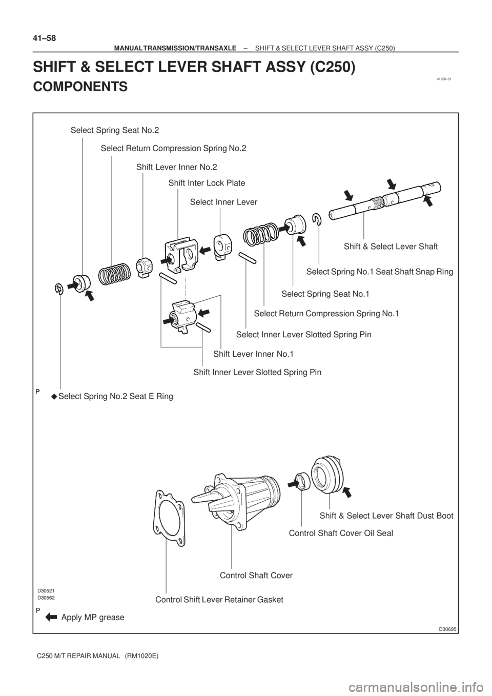
Select Spring Seat No.2
�
Apply MP greaseSelect Spring No.2 Seat E Ring
Shift Lever Inner No.1
Shift Inner Lever Slotted Spring Pin Select Return Compression Spring No.2
Shift Lever Inner No.2
Shift Inter Lock Plate
Select Inner Lever
Select Return Compression Spring No.1
Select Inner Lever Slotted Spring Pin
Select Spring Seat No.1
Select Spring No.1 Seat Shaft Snap Ring
Shift & Select Lever Shaft
Control Shift Lever Retainer Gasket
Control Shaft Cover
Control Shaft Cover Oil SealShift & Select Lever Shaft Dust Boot
41±58
± MANUAL TRANSMISSION/TRANSAXLESHIFT & SELECT LEVER SHAFT ASSY (C250)
C250 M/T REPAIR MANUAL (RM1020E)
SHIFT & SELECT LEVER SHAFT ASSY (C250)
COMPONENTS
Page 4732 of 5135
F40217
SSTTurn
Hold
C80293
D27403
F40148SST
− DRIVE SHAFT / PROPELLER SHAFTFRONT DRIVE SHAFT (2AZ−FSE)
30−5
AVENSIS Supplement (RM1045E)
7. SEPARATE TIE ROD END SUB−ASSY LH
(a) Remove the cotter pin and nut.
(b) Using SST, separate the tie rod end sub−assy LH from the
steering knuckle.
SST 09628−62011
8. SEPARATE FRONT SUSPENSION ARM SUB−ASSY
LOWER NO.1LH
(a) Remove the bolt and 2 nuts, and separate the front sus-
pension arm sub−assy lower No.1LH from the lower ball
joint.
9. SEPARATE FRONT AXLE ASSY LH
(a) Using a plastic hammer, separate the front drive shaft
assy LH from the axle hub.
NOTICE:
Be careful not to damage the boot and speed sensor rotor.
10. REMOVE FRONT DRIVE SHAFT ASSY LH
(a) Using SST, remove the front drive shaft assy LH.
SST 09520−01010, 09520−24010 (09520−32040)
NOTICE:
SBe careful not to damage the oil seal, boot and dust
cover.
SBe careful not to drop the drive shaft assy.
Page 4733 of 5135

AVENSIS Supplement (RM1045E)
11. REMOVE FRONT DRIVE SHAFT ASSY RH (RH DRIVE
SHAFT)
(a) Remove the")
C83155
F40218
SST
C91598
C86265
30−6
− DRIVE SHAFT / PROPELLER SHAFTFRONT DRIVE SHAFT (2AZ−FSE)
AVENSIS Supplement (RM1045E)
11. REMOVE FRONT DRIVE SHAFT ASSY RH (RH DRIVE
SHAFT)
(a) Remove the 2 bolts and pull out the drive shaft together
with the center bearing bracket.
(b) Remove the drive shaft from the transaxle.
NOTICE:
SBe careful not to damage the oil seal, boot and dust
cover.
SBe careful not to drop the drive shaft assy.
12. FIX FRONT AXLE HUB LH BEARING
NOTICE:
The hub bearing may become damaged if subjected to the
vehicle weight. For example, moving the vehicle with the
drive shaft removed.
Therefore, if it is absolutely necessary to place the vehicle
weight on the hub bearing, first support it with SST.
SST 09608−16042 (09608−02021, 09608−02041)
13. INSPECT FRONT DRIVE SHAFT ASSY LH
(a) Check that there is no excessive play in the radial direc-
tion of the outboard joint.
(b) Check that the inboard joint slides smoothly in the thrust
direction.
(c) Check that there is no excessive play in the radial direc-
tion of the inboard joint.
(d) Check the boots for damage.
NOTICE:
Keep the drive shaft assy level during inspection.
14. REMOVE FRONT AXLE INBOARD JOINT BOOT
CLAMP
(a) Using pliers, remove the inboard joint boot LH No.2 clamp
as shown in the illustration.
(b) Remove the inboard joint boot LH clamp ifollwng the
same procedure as for the inboard joint boot LH No.2
clamp.
15. REMOVE FR AXLE INBOARD JOINT BOOT
(a) Remove the inboard joint boot from the inboard joint assy LH.
Page 4734 of 5135

30−7
AVENSIS Supplement (RM1045E)
16. REMOVE FRONT DRIVE INBOARD JOINT A")
C67413F45461
Matchmarks
G24058
C91601
Matchmarks
F44759
C81167
− DRIVE SHAFT / PROPELLER SHAFTFRONT DRIVE SHAFT (2AZ−FSE)
30−7
AVENSIS Supplement (RM1045E)
16. REMOVE FRONT DRIVE INBOARD JOINT ASSY LH
(a) Remove the old grease from the inboard joint.
(b) Place matchmarks on the inboard joint assy LH and out-
board joint shaft assy LH.
NOTICE:
Do not use a punch for the marks.
(c) Remove the inboard joint assy LH from the outboard joint
shaft assy LH.
(d) Using a snap ring expander, remove the shaft snap ring.
(e) Place matchmarks on the outboard joint shaft assy LH
and tripod joint assy.
NOTICE:
Do not punch the marks.
(f) Using a brass bar and hammer, remove the tripod joint
assy from the outboard joint shaft assy LH.
NOTICE:
Do not tap the roller.
(g) Remove the inboard joint boot and 2 clamps.
17. REMOVE FRONT DRIVE SHAFT DAMPER LH
(a) Using pliers, remove the damper clamp as shown in the
illustration.
(b) Remove the drive shaft damper.
18. REMOVE FRONT AXLE OUTBOARD JOINT BOOT
CLAMP
(a) Using pliers, remove the outboard joint boot LH No.2
clamp as shown in the illustration.
(b) Remove the outboard joint boot LH clamp following the
same procedure as for the outboard joint boot LH No.2
clamp.
Page 4735 of 5135
C57543
F40647
SST
C67101
C68337
30−8
− DRIVE SHAFT / PROPELLER SHAFTFRONT DRIVE SHAFT (2AZ−FSE)
AVENSIS Supplement (RM1045E)
19. REMOVE OUTBOARD JOINT BOOT
(a) Remove the outboard joint boot from the outboard joint shaft assy LH.
(b) Remove the old grease from the outboard joint.
20. REMOVE FRONT DRIVE SHAFT LH HOLE SNAP RING
(a) Using a screwdriver, remove the hole snap ring.
21. REMOVE FRONT DRIVE SHAFT DUST COVER LH
(a) Using SST and a press, remove the front drive shaft dust
cover LH.
SST 09950−00020
NOTICE:
Be careful not to drop the inboard joint assy.
22. REMOVE FRONT DRIVE SHAFT DUST COVER RH (RH
DRIVE SHAFT)
(a) Using a press, remove the drive shaft dust cover RH.
23. REMOVE CASE SUB ASSY, DRIVE SHAFT BEARING
SNAP RING (RH DRIVE SHAFT)
(a) Using a screwdriver, remove the bearing case snap ring.
Page 4738 of 5135

30−11
AVENSIS Supplement (RM1045E)
(b) Using SST and a press, install a new driv")
C63297F45152
SST
W01994
Vinyl Tape
R10425
SSTHold
Turn
− DRIVE SHAFT / PROPELLER SHAFTFRONT DRIVE SHAFT (2AZ−FSE)
30−11
AVENSIS Supplement (RM1045E)
(b) Using SST and a press, install a new drive shaft dust cov-
er RH.
SST 09527−10011
NOTICE:
SDust cover should be installed completely.
SBe careful not to damage the dust cover.
32. INSTALL FRONT DRIVE SHAFT DUST COVER LH
(a) Using SST and a press, install a new drive shaft dust cover LH.
SST 09527−10011
NOTICE:
SDust cover should be installed completely.
SBe careful not to damage the dust cover.
33. INSTALL FRONT DRIVE SHAFT LH HOLE SNAP RING
(a) Install a new hole snap ring.
34. INSTALL OUTBOARD JOINT BOOT
HINT:
Before installing the boots, wrap the drive shaft spline with vinyl
tape to prevent the boots from being damaged.
(a) Install new parts to the outboard joint shaft assy in the fol-
lowing order.
(1) Outboard joint boot LH No.2 clamp
(2) Outboard joint boot
(3) Outboard joint boot LH clamp
(b) Pack the outboard joint shaft and boot with grease in the
boot kit.
Grease capacity:152 to162 g (5.4 to 5.7 oz.)
35. INSTALL FRONT AXLE OUTBOARD JOINT BOOT
CLAMP
(a) Hold the front drive shaft in a soft vise.
(b) Secure the 2 outboard joint boot clamps onto the boot.
(c) Place SST onto the outboard joint large boot clamp.
SST 09521−24010
(d) Tighten the SST so that the large clamp is pinched.
NOTICE:
Do not overtighten the SST.
Page 4739 of 5135

AVENSIS Supplement (RM1045E)
(e) Using SST, adjust the clearance of the large clamp")
R10426
SST
F40646Distance
C86267
SSTHold
Turn 30−12
− DRIVE SHAFT / PROPELLER SHAFTFRONT DRIVE SHAFT (2AZ−FSE)
AVENSIS Supplement (RM1045E)
(e) Using SST, adjust the clearance of the large clamp.
SST 09240−00020
Clearance: 0.8 mm (0.031in.) or less
(f) Install the outboard joint boot LH clamp following the
same procedure as for the outboard joint boot LH No.2
clamp.
NOTICE:
When the measured value exceeds the specified value, re-
tighten the clamp.
36. INSTALL FRONT DRIVE SHAFT DAMPER LH
HINT:
Perform the above procedure only when reassembling the RH
side.
(a) Temporarily install a new damper clamp.
(b) Set the distance as described below.
Drive shaft typeDistance mm (in.)
RH212.0�á2.0
(8.35�á0.08)
LH168.0�á2.0
(6.61�á0.08)
(c) Install the damper clamp.
HINT:
Install the damper clamp to inboard joint side.
(1) Hold the front drive shaft in a soft vise.
(2) Secure the damper clamp onto the damper.
(3) Place SST onto the damper clamp.
SST 09521−24010
(4) Tighten the SST so that the damper clamp is
pinched.
NOTICE:
Do not overtighten the SST.

30−5
AVENSIS Supplement (RM1045E)
7. SEPARATE TIE ROD END SUB−ASSY LH
(a) Remove the cott")

AVENSIS Supplement (RM1045E)
19. REMOVE OUTBOARD JOINT BOOT
(a) Remove the outboard joint boot fro")