Page 2847 of 5135
 or less
SST(s)
± POWER STEERINGRACK & PINION POWER STEERING GEAR ASSY
51±41
AVENSIS REPAIR MANUAL (RM1018E)
29. REMOVE STEERING RACK BOOT NO.1 CLAMP
HINT:
Perform the")
C57755
F400843 mm (0.12 in.) or less
SST(s)
± POWER STEERINGRACK & PINION POWER STEERING GEAR ASSY
51±41
AVENSIS REPAIR MANUAL (RM1018E)
29. REMOVE STEERING RACK BOOT NO.1 CLAMP
HINT:
Perform the same procedure on the other side.
30. REMOVE STEERING RACK BOOT CLIP
HINT:
Perform the same procedure on the rack boot clamps.
31. REMOVE STEERING RACK BOOT NO.2
32. REMOVE STEERING RACK BOOT NO.1
33. INSTALL STEERING RACK BOOT NO.2
(a) Apply silicon grease to the inside small caliber of rack
boot No.2.
(b) Install the rack boot No.2 to the groove on the rack hous-
ing.
NOTICE:
Be careful not to damage or twist the boot.
34. INSTALL STEERING RACK BOOT NO.1
HINT:
Perform the same procedure on the other side.
35. INSTALL STEERING RACK BOOT NO.2 CLAMP
(a) Install a new rack boot No.2 clamp.
(b) Using SST(s), stake the rack boot No.2 clamp as shown
in the illustration.
SST 09521±24010
36. INSTALL STEERING RACK BOOT NO.1 CLAMP
SST 09521±24010
HINT:
Perform the same procedure on the other side.
37. INSTALL STEERING RACK BOOT CLIP
SST 09521±24010
HINT:
Perform the same procedure on the rack boot clamps.
Page 2853 of 5135
D30602
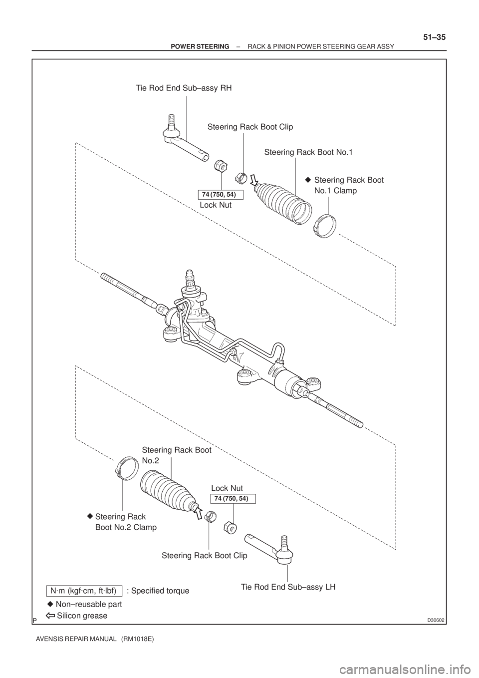
Tie Rod End Sub±assy RH
Lock NutSteering Rack Boot Clip
Steering Rack Boot No.1
Steering Rack Boot
No.1 Clamp �
Lock Nut
Steering Rack
Boot No.2 Clamp �
Steering Rack Boot
No.2
Steering Rack Boot Clip
Tie Rod End Sub±assy LH
� Non±reusable part
Silicon greaseN�m (kgf�cm, ft�lbf) : Specified torque
74 (750, 54)
74 (750, 54)
± POWER STEERINGRACK & PINION POWER STEERING GEAR ASSY
51±35
AVENSIS REPAIR MANUAL (RM1018E)
Page 2856 of 5135

SST(s)Hold
Turn
F40051
SST(s) 51±30
± POWER STEERINGSTEERING GEAR ASSY
AVENSIS REPAIR MANUAL (RM1018E)
25. INSPECT TIE ROD END SUB±ASSY LH
(a) Secure the tie rod end s")
ZK8184
F40083
F40052
SST(s)
SST(s)Hold
Turn
F40051
SST(s) 51±30
± POWER STEERINGSTEERING GEAR ASSY
AVENSIS REPAIR MANUAL (RM1018E)
25. INSPECT TIE ROD END SUB±ASSY LH
(a) Secure the tie rod end sub±assy in a vise.
(b) Install the nut to the stud bolt.
(c) Flip the ball joint stud back and forth 5 times.
(d) Using a torx wrench, turn the nut continuously at a rate of
2 to 4 seconds per turn and take the torque reading on the
5th turn.
Turning torque:
0.29 to 1.96 N�m (3 to 20 kgf�cm, 2.57 to 17.35 in.�lbf)
26. INSPECT TIE ROD END SUB±ASSY RH
HINT:
Perform the same procedure on the other side.
27. REMOVE STEERING RACK BOOT CLIP
(a) Using a pliers, remove the 2 boot clips from each rack boots.
28. REMOVE STEERING RACK BOOT NO.2 CLAMP
(a) Using a screwdriver, unstake the rack boot No.2 clamp.
NOTICE:
Be careful not to damage the boot.
29. REMOVE STEERING RACK BOOT NO.1 CLAMP
HINT:
Perform the same procedure on the other side.
30. REMOVE STEERING RACK BOOT NO.2
31. REMOVE STEERING RACK BOOT NO.1
32. REMOVE STEERING RACK END SUB±ASSY
(a) Using SST(s), hold the steering rack steadily and using
another SST(s), remove the rack end sub±assy.
SST 09922±10010
NOTICE:
Use SST(s) 09922±10010 in the direction shown in the il-
lustration.
HINT:
Perform the same procedure on the other side.
33. INSPECT TOTAL PRELOAD
(a) Temporarily install the RH and LH rack end sub±assy.
(b) Using SST(s) and a torque wrench, check the preload.
SST 09616±00011
Preload (turning):
0.6 to 1.1 N�m (6 to 11 kgf�cm, 5.3 to 9.7 in.�lbf)
If it is not within specification, replace the steering gear assy.
Page 2857 of 5135

SST(s)
Fulcrum
Length
Hold
Turn
C57755
F400843 mm (0.12 in.) or lessSST(s)
± POWER STEERINGSTEERING GEAR ASSY
51±31
AVENSIS REPAIR MANUAL (RM1018E)
34. INSTALL STEERING RACK END SUB")
F40053
SST(s)
SST(s)
Fulcrum
Length
Hold
Turn
C57755
F400843 mm (0.12 in.) or lessSST(s)
± POWER STEERINGSTEERING GEAR ASSY
51±31
AVENSIS REPAIR MANUAL (RM1018E)
34. INSTALL STEERING RACK END SUB±ASSY
(a) Using SST(s), hold the steering rack steadily and using
another SST(s), torque the rack end sub±assy.
SST 09922±10010
Torque: 60 N�m (616 kgf�cm, 45 ft�lbf)
NOTICE:
Use SST(s) 09922±10010 in the direction shown in the il-
lustration.
HINT:
�Use a torque wrench with a fulcrum length of 345 mm
(13.58 in.)
�Perform the same procedure on the other side.
35. INSTALL STEERING RACK BOOT NO.2
(a) Apply silicon grease to the inside small caliber of rack
boot No.2.
(b) Install the rack boot No.2 to the groove on the rack hous-
ing.
NOTICE:
Be careful not to damage or twist the boot.
36. INSTALL STEERING RACK BOOT NO.1
HINT:
Perform the same procedure on the other side.
37. INSTALL STEERING RACK BOOT NO.2 CLAMP
(a) Install a new rack boot No.2 clamp to the rack boot No.2.
(b) Using SST(s), stake the rack boot No.2 clamp as shown
in the illustration.
SST 09521±24010
38. INSTALL STEERING RACK BOOT NO.1 CLAMP
SST 09521±24010
HINT:
Perform the same procedure on the other side.
Page 2858 of 5135

F40050
Matchmarks
C80324
F40259
Matchmarks
51±32
±
POWER STEERING STEERING GEAR ASSY
AVENSIS REPAIR MANUAL (RM1018E)
39. INSTALL STEERING RACK BOOT CLIP
(a) Using a pliers, install t")
D30584
SST(s)
F40050
Matchmarks
C80324
F40259
Matchmarks
51±32
±
POWER STEERING STEERING GEAR ASSY
AVENSIS REPAIR MANUAL (RM1018E)
39. INSTALL STEERING RACK BOOT CLIP
(a) Using a pliers, install the 2 rack boot clips to each rack boots.
(b) Using SST(s), check that the rack boot No.2 is strechy. SST 09616±00011
40. INSTALL TIE ROD END SUB±ASSY LH
(a) Screw the lock nut and the tie rod end sub±assy to the rack end sub±assy until the matchmarks are aligned.
Torque: 74 N �m (750 kgf �cm, 54 ft �lbf)
HINT:
After adjusting toe±in, torque the lock nut
(See page 26±6).
41. INSTALL TIE ROD END SUB±ASSY RH
HINT:
Perform the same procedure on the other side. 42. INSTALL STEERING GEAR ASSY
(a) Install the steering gear assy onto the crossmember sub±assy with the 4 bolts and the nuts.
Torque: 49 N �m (500 kgf �cm, 36 ft �lbf)
NOTICE:
Because the nut has its own stopper, do not turn the nut
and torque the bolt with the nut fixed.
43. INSTALL STEERING INTERMEDIATE SHAFT
(a) Align the matchmarks on the steering intermediate shaft and the steering pinion shaft.
(b) Install the bolt. Torque: 35 N �m (360 kgf �cm, 26 ft �lbf)
44. INSTALL STEERING COLUMN HOLE COVER SUB±ASSY NO.1
45.INSTALL FRONT SUSPENSION CROSSMEMBER SUB±ASSY (See page 51±36)
Page 2860 of 5135

89 (908, 66)
Front Stabilizer
Link Assy RH
74 (755, 55)
133 (1,356, 98)
80 (816, 59)
Stopper Rear
80 (816, 59)
52 (530, 38)
45 (459, 33)Center Member
52")
510DI±02
D30014
Stopper
Front
133 (1,356, 98)
89 (908, 66)
Front Stabilizer
Link Assy RH
74 (755, 55)
133 (1,356, 98)
80 (816, 59)
Stopper Rear
80 (816, 59)
52 (530, 38)
45 (459, 33)Center Member
52 (530, 38)
133 (1,356, 98)
Stopper Front
89 (908, 66)
80 (816, 59)
133 (1,356, 98)
80 (816, 59)
Stopper Rear
Crossmember
Bracket LH
74 (755, 55)
Front Stabilizer Link Assy LH
Front Suspension
Crossmember Sub±assy
Clip
Steering Intermediate Shaft
Assy No.2
35 (360, 26)
Steering Intermediate Shaft
Steering Column Hole
Cover Sub±assy No.1
Tie Rod End
Sub±assy RH
49 (500, 36)
74 (750, 54)
Lock Nut
Steering Rack
Boot Clip
Steering Rack
Boot No.1
49 (500, 36)
Steering Rack Boot
No.1 Clamp �
Steering Rack
End Sub±assy
Lock Nut
Steering Rack Boot
No.2 Clamp �
Steering Rack
Boot No.2
Steering Rack
Boot Clip
Tie Rod End
Sub±assy LH
49 (500, 36)
�Cotter Pin
N�m (kgf�cm, ft�lbf) : Specified torque � Non±reusable part
Slicon grease
Engine Under Cover LH
Column Hole Cover
Silencer Sheet
Molybdenum disulfide lithium base grease
49 (500, 36)
49 (500, 36)
* For use with SST(s)
83.5 (851, 62)
*60 (616, 45)
74 (750, 54)
± POWER STEERINGSTEERING GEAR ASSY
51±27
AVENSIS REPAIR MANUAL (RM1018E)
STEERING GEAR ASSY
COMPONENTS
Page 3537 of 5135
C67604
D30525
D30526
SST
D30527
D30528
± MANUAL TRANSMISSION/TRANSAXLEMANUAL TRANSAXLE ASSY (C250)
41±5
C250 M/T REPAIR MANUAL (RM1020E)
6. REMOVE RELEASE FORK SUPPORT
(a) Remove the clutch release fork support from the front
transaxle case.
7. REMOVE CLUTCH RELEASE FORK BOOT
(a) Remove the clutch release fork boot from the front trans-
axle case.
8. REMOVE BACK UP LAMP SWITCH ASSY
(a) Using SST, remove the back±up lamp switch assy and
gasket from the manual transmission case.
SST 09817±16011
9. REMOVE FLOOR SHIFT CONTROL LEVER HOUSING
SUPPORT BRACKET
(a) Remove the 3 bolts and control cable bracket from the
front transaxle case.
10. REMOVE SELECTING BELL CRANK ASSY
(a) Remove the 2 bolts and selecting bell crank assy from the
manual transmission case.
Page 3567 of 5135

41±35
C250 M/T REPAIR MANUAL (RM1020E)
107. INSTALL RELEASE FORK SUPPORT
(a) Install the release fork")
C67604
D30525
C67602
C68381
D30524
± MANUAL TRANSMISSION/TRANSAXLEMANUAL TRANSAXLE ASSY (C250)
41±35
C250 M/T REPAIR MANUAL (RM1020E)
107. INSTALL RELEASE FORK SUPPORT
(a) Install the release fork support to the front transaxle case.
Torque: 37 N�m (375 kgf�cm, 25 ft�lbf)
108. INSTALL CLUTCH RELEASE FORK BOOT
(a) Install the clutch release fork boot to the front transaxle
case.
109. INSTALL CLUTCH RELEASE BEARING ASSY
(a) Coat the clutch release bearing assy with release hub
grease, install it to the clutch release fork sub±assy.
Sealant:
Part No. 08887±01806, RELEASE HUB GREASE or
equivalent
110. INSTALL CLUTCH RELEASE FORK SUB±ASSY
(a) Install the clutch release fork sub±assy to the input shaft.
Sealant:
Part No. 08887±01806, CLUTCH SPLINE GREASE or
equivalent
(b) Apply clutch spline grease to the input shaft spline.
111. INSTALL MANUAL TRANSMISSION FILLER PLUG
(a) Install the manual transmission filler plug with new gasket
to the manual transmission case.
Torque: 39 N�m (400 kgf�cm, 29 ft�lbf)

41±5
C250 M/T REPAIR MANUAL (RM1020E)
6. REMOVE RELEASE FORK SUPPORT
(a) Remove the clutch releas")