Page 2826 of 5135

42±29
AVENSIS REPAIR MANUAL (RM1018E)
16. INSTALL RELEASE FORK SUPPORT
(a) Install the relea")
D26819
EXCEPT 1CD±FTV Engine Type:
1CD±FTV Engine Type:
Release Hub Grease
±
CLUTCH CLUTCH UNIT (MTM)
42±29
AVENSIS REPAIR MANUAL (RM1018E)
16. INSTALL RELEASE FORK SUPPORT
(a) Install the release fork support to the transaxle assy.
Torque:
1ZZ±FE/3ZZ±FE/1CD±FTV Engine Type: 37 N �m (375 kgf �cm, 27 ft �lbf)
1AZ±FSE/1AZ±FE Engine Type: 47 N �m (480 kgf �cm, 35 ft �lbf)
17. INSTALL RELEASE BEARING HUB CLIP
18. INSTALL CLUTCH RELEASE FORK SUB±ASSY
(a) Apply the release hub grease to the release fork and re-lease bearing assy contact, release fork and push rod
contact, and release fork pivot points.
Sealant:
Part No. 08887±01806, RELEASE HUB GREASE or
equivalent
(b) Install the release fork to the release bearing assy.
19. INSTALL CLUTCH RELEASE BEARING ASSY
(a) Apply the clutch spline grease to the input shaft spline. Sealant:
Part No. 08887±01706, CLUTCH SPLINE GREASE or equivalent
(b) Install the bearing to the release fork, and then install them to the tr\
ansaxle assy.
NOTICE:
After the installation, move the folk forward and backward to check that\
the release bearing slides
smoothly.
20. INSTALL CLUTCH RELEASE FORK BOOT
21. INSTALL MANUAL TRANSAXLE ASSY
(a)1ZZ±FE, 3ZZ±FE Engine (See page 41±15)
(b)1AZ±FE, 1AZ±FSE Engine (See page 41±24)
(c)1CD±FTV Engine (See page 41±33)
Page 2827 of 5135
4206H±01
D26321
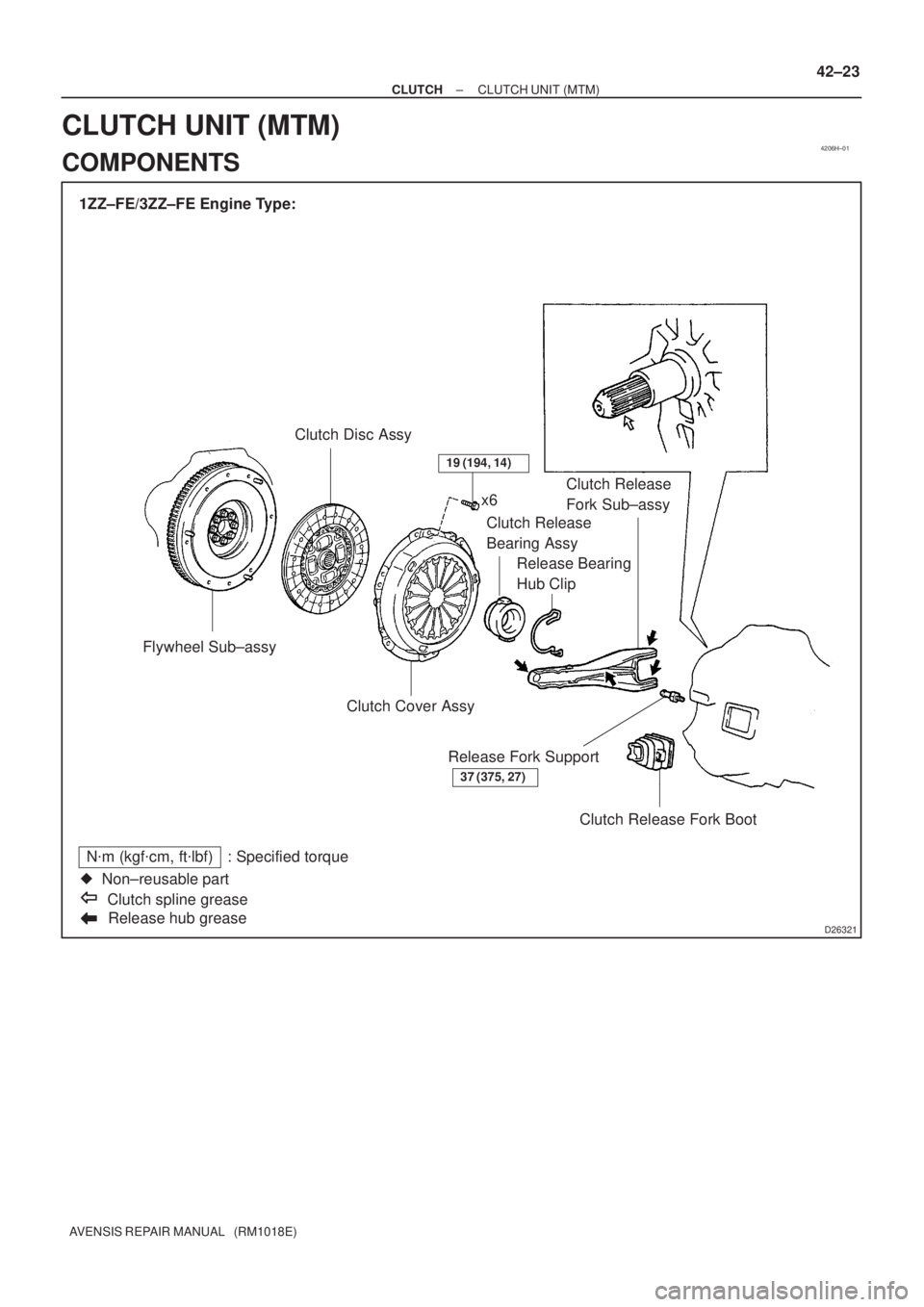
1ZZ±FE/3ZZ±FE Engine Type:
Flywheel Sub±assyClutch Disc Assy
Release hub grease
N�m (kgf�cm, ft�lbf) : Specified torque
�Non±reusable part
Clutch spline greasex6
Clutch Release
Bearing Assy
Release Bearing
Hub ClipClutch Release
Fork Sub±assy
Clutch Cover Assy
Clutch Release Fork Boot Release Fork Support
37 (375, 27)
19 (194, 14)
± CLUTCHCLUTCH UNIT (MTM)
42±23
AVENSIS REPAIR MANUAL (RM1018E)
CLUTCH UNIT (MTM)
COMPONENTS
Page 2828 of 5135
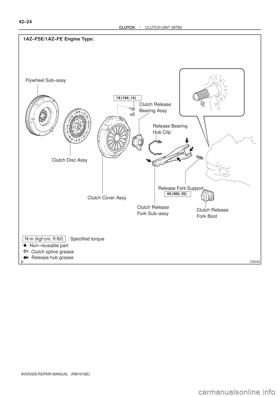
D30056Release hub grease
N�m (kgf�cm, ft�lbf) : Specified torque
�Non±reusable part
Clutch spline grease 1AZ±FSE/1AZ±FE Engine Type:
Flywheel Sub±assy
Clutch Disc Assy
Clutch Release
Fork Sub±assy Clutch Cover AssyRelease Bearing
Hub Clip Clutch Release
Bearing Assy
Release Fork Support
Clutch Release
Fork Boot
48 (480, 35)
19 (194, 14)
x6 42±24
± CLUTCHCLUTCH UNIT (MTM)
AVENSIS REPAIR MANUAL (RM1018E)
Page 2829 of 5135
D30057
1CD±FTV Engine Type:
Flywheel Sub±assyClutch Disc Assy
Clutch Release Fork Sub±assy Clutch Cover Assy
Release Bearing
Hub Clip Clutch Release
Bearing Assy
Release Fork Support
Clutch Release
Fork Boot
37 (375, 27)
19 (194, 14)
x6
Release hub grease
N�m (kgf�cm, ft�lbf) : Specified torque
�Non±reusable part
Clutch spline grease
± CLUTCHCLUTCH UNIT (MTM)
42±25
AVENSIS REPAIR MANUAL (RM1018E)
Page 2833 of 5135

AVENSIS REPAIR MANUAL (RM1018E)
5. REMOVE CLUTCH RELEASE CYLINDER ASSY
(")
D30488
1ZZ±FE/3ZZ±FE Engine Type:
1AZ±FE/1AZ±FSE Engine Type:
D26804
42±18
± CLUTCHCLUTCH RELEASE CYLINDER ASSY (MTM)
AVENSIS REPAIR MANUAL (RM1018E)
5. REMOVE CLUTCH RELEASE CYLINDER ASSY
(EXCEPT 1CD±FTV ENGINE TYPE)
(a) 1ZZ±FE/3ZZ±FE Engine Type:
Remove the 3 bolts, clutch release cylinder assy, and
clutch line bracket.
(b) 1AZ±FE/1AZ±FSE Engine Type:
Remove the 3 bolts and clutch release cylinder assy.
6. REMOVE CLUTCH RELEASE CYLINDER ASSY
(1CD±FTV ENGINE TYPE)
(a) Using a 12 mm deep socket wrench, remove the 2 bolts
and clutch release cylinder assy.
7. REMOVE CLUTCH RELEASE CYLINDER KIT
(a) Remove the boot from the cylinder body.
(b) Remove the push rod from the cylinder body.
(c) Remove the piston from the cylinder body.
NOTICE:
Be careful not to damage the inside of the cylinder body.
(d) Remove the spring from the cylinder body.
(e) Remove the bleeder plug cap from the bleeder plug.
8. REMOVE RELEASE CYLINDER BLEEDER PLUG
9. INSTALL RELEASE CYLINDER BLEEDER PLUG
Torque: 8.3 N�m (85 kgf�cm, 73 in.�lbf)
Page 2834 of 5135

(1)
(1)
(1)
(2) (2)
± CLUTCHCLUTCH RELEASE CYLINDER ASSY (MTM)
42±19
AVENSIS REPAIR MANUAL (RM1018E)
10. INSTAL")
CL0672
D26804
D30488
1ZZ±FE/3ZZ±FE Engine Type:
1AZ±FE/1AZ±FSE Engine Type:(1)
(1)
(1)
(1)
(2) (2)
± CLUTCHCLUTCH RELEASE CYLINDER ASSY (MTM)
42±19
AVENSIS REPAIR MANUAL (RM1018E)
10. INSTALL CLUTCH RELEASE CYLINDER KIT
(a) Install the bleeder plug cap to the bleeder plug.
(b) Install a new spring to the cylinder body.
(c) Coat the parts with lithium soap base glycol grease, as
shown in the illustration.
(d) Install the piston to the cylinder body.
NOTICE:
Be careful not to damage the inside of the cylinder body.
(e) Install the push rod to the cylinder body.
(f) Install the boot to the cylinder body.
11. INSTALL CLUTCH RELEASE CYLINDER ASSY
(1CD±FTV ENGINE TYPE)
(a) Using a 12 mm deep socket wrench, install the clutch re-
lease cylinder assy with the 2 bolts.
Torque: 12 N�m (120 kgf�cm, 9 ft�lbf)
12. INSTALL CLUTCH RELEASE CYLINDER ASSY
(EXCEPT 1CD±FTV ENGINE TYPE)
(a) 1ZZ±FE/3ZZ±FE Engine Type:
(1) Install the clutch release cylinder and clutch line
bracket with the 2 bolts.
Torque: 14 N�m (141 kgf�cm, 10 ft�lbf)
(2) Install the flexible hose tube with the bolt.
Torque: 5.0 N�m (51 kgf�cm, 44 in.�lbf)
(b) 1AZ±FE/1AZ±FSE Engine Type:
(1) Install the clutch release cylinder with the 2 bolts.
Torque: 12 N�m (120 kgf�cm, 9 ft�lbf)
(2) Install the flexible hose tube with the bolt.
Torque: 12 N�m (122 kgf�cm, 9 ft�lbf)
Page 2836 of 5135
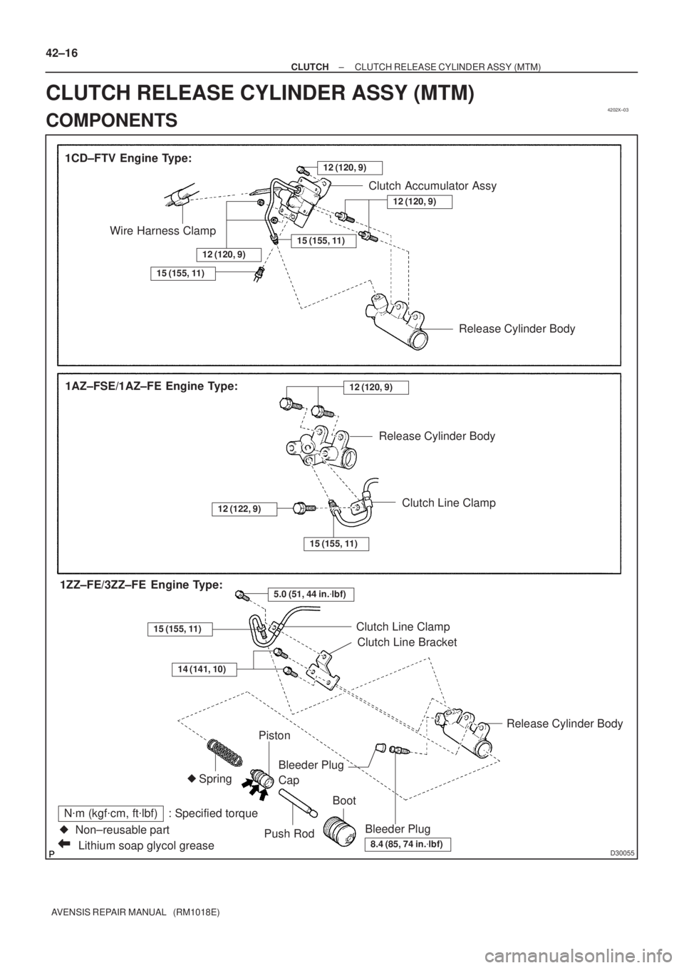
4202X±03
D30055Lithium soap glycol grease
N�m (kgf�cm, ft�lbf) : Specified torque
�Non±reusable part 1CD±FTV Engine Type:
Bleeder PlugRelease Cylinder Body
Piston
Push RodBoot Bleeder Plug
Cap
8.4 (85, 74 in.�lbf)
Wire Harness ClampClutch Accumulator Assy
Spring
1AZ±FSE/1AZ±FE Engine Type:
15 (155, 11)
12 (120, 9)
�
12 (120, 9)
Release Cylinder Body
12 (120, 9)
Release Cylinder Body
Clutch Line Clamp
Clutch Line Bracket
15 (155, 11)
12 (122, 9)
5.0 (51, 44 in.�lbf)1ZZ±FE/3ZZ±FE Engine Type:
15 (155, 11)Clutch Line Clamp
14 (141, 10)
15 (155, 11)
12 (120, 9)
42±16
± CLUTCHCLUTCH RELEASE CYLINDER ASSY (MTM)
AVENSIS REPAIR MANUAL (RM1018E)
CLUTCH RELEASE CYLINDER ASSY (MTM)
COMPONENTS
Page 2846 of 5135

23. REMOVE RACK & PINION POWER STEERING GEAR
ASSY
(a) Remove the")
D30594
F40050
Matchmarks
ZK8184
F40083
51±40
± POWER STEERINGRACK & PINION POWER STEERING GEAR ASSY
AVENSIS REPAIR MANUAL (RM1018E)
23. REMOVE RACK & PINION POWER STEERING GEAR
ASSY
(a) Remove the 4 bolts, the nuts and the power steering gear
assy from the crossmember sub±assy.
NOTICE:
Because the nut has its own stopper, do not turn the nut
and torque the bolt with the nut fixed.
24. REMOVE TIE ROD END SUB±ASSY LH
(a) Place matchmarks on the tie rod end sub±assy and the
rack end.
(b) Loosen the lock nut, and remove the tie rod end sub±assy
and the lock nut.
25. REMOVE TIE ROD END SUB±ASSY RH
HINT:
Perform the same procedure on the other side.
26. INSPECT TIE ROD END SUB±ASSY LH
(a) Secure the tie rod end sub±assy in a vise.
(b) Install the nut to the stud bolt.
(c) Flip the ball joint stud back and forth 5 times.
(d) Using a torx wrench, turn the nut continuously at a rate of
2 to 4 seconds per turn and take the torque reading on the
5th turn.
Turning torque:
0.49 to 3.43 N�m (5.0 to 35 kgf�cm, 4.34 to 30.38 in. lbf)
27. INSPECT TIE ROD END SUB±ASSY RH
HINT:
Perform the same procedure on the other side.
28. REMOVE STEERING RACK BOOT NO.2 CLAMP
(a) Using a screwdriver, remove the rack boot No.2 clamp.
NOTICE:
Be careful not to damage the boot.