Page 1093 of 5135

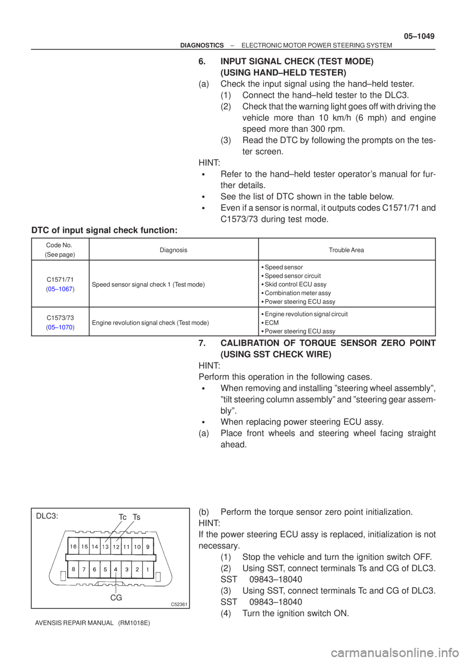
C52361
DLC3:CGTs
Tc
±
DIAGNOSTICS ELECTRONIC MOTOR POWER STEERING SYSTEM
05±1049
AVENSIS REPAIR MANUAL (RM1018E)
6.INPUT SIGNAL CHECK (TEST MODE)
(USING HAND±HELD TESTER)
(a)Check the input signal using the hand±held tester.
(1)Connect the hand±held tester to the DLC3.
(2)Check that the warning light goes off with driving thevehicle more than 10 km/h (6 mph) and engine
speed more than 300 rpm.
(3)Read the DTC by following the prompts on the tes- ter screen.
HINT:
�Refer to the hand±held tester operator's manual for fur-
ther details.
�See the list of DTC shown in the table below.
�Even if a sensor is normal, it outputs codes C1571/71 and
C1573/73 during test mode.
DTC of input signal check function:
Code No.
(See page)DiagnosisTrouble Area
C1571/71
(05±1067)Speed sensor signal check 1 (Test mode)
� Speed sensor
� Speed sensor circuit
� Skid control ECU assy
� Combination meter assy
� Power steering ECU assy
C1573/73
(05±1070)Engine revolution signal check (Test mode)
� Engine revolution signal circuit
� ECM
� Power steering ECU assy
7. CALIBRATION OF TORQUE SENSOR ZERO POINT
(USING SST CHECK WIRE)
HINT:
Perform this operation in the following cases.
�When removing and installing ºsteering wheel assemblyº,
ºtilt steering column assemblyº and ºsteering gear assem-
blyº.
�When replacing power steering ECU assy.
(a) Place front wheels and steering wheel facing straight ahead.
(b) Perform the torque sensor zero point initialization.
HINT:
If the power steering ECU assy is replaced, initialization is not
necessary. (1) Stop the vehicle and turn the ignition switch OFF.
(2) Using SST, connect terminals Ts and CG of DLC3.
SST 09843±18040
(3) Using SST, connect terminals Tc and CG of DLC3.
SST 09843±18040
(4) Turn the ignition switch ON.
Page 1100 of 5135
±
DIAGNOSTIC SELECTRONI C MO TOR POWER STEERING SYSTEM
05±1043
A VENSIS RE PAIR MANUAL (RM1018E)
9 CIRCUIT INSPECTION( See page 05±1059 to 05±1086 )
10 IDENTIFYING PROBLEMS 11 REPAIR
12 CONFIRMATION TEST
END
Page 1101 of 5135
D30688
ECM
MPX2
MPX1 29
23 E10 11
I14
22 SNOWI14
Integration Relay
8
Driver Side J/B14
DA B E8
ECT Pattern Select SW
*1: RHD
*2: LHD 4 1 W±B
CH
CF
CA 8
11
6
W±B
IPI14 E10 MPX1
MPX2
*1
*2
05±1040± DIAGNOSTICSELECTRONIC CONTROLLED AUTOMATIC
TRANSAXLE [ECT] (U341E)
AVENSIS REPAIR MANUAL (RM1018E)
PATTERN SELECT SWITCH CIRCUIT
CIRCUIT DESCRIPTION
When SNOW mode is selected with the pattern select switch, the ECM controls the solenoid valves and the
transmission starts from 2nd gear.
In D range, the transmission automatically shifts up through 3rd to O/D as usual.
WIRING DIAGRAM
05C8Q±01
Page 1102 of 5135
D30685
± DIAGNOSTICSELECTRONIC CONTROLLED AUTOMATIC
TRANSAXLE [ECT] (U341E)05±1041
AVENSIS REPAIR MANUAL (RM1018E)
INSPECTION PROCEDURE
1 INSPECT PATTERN SELECT SWITCH ASSY
(a) Disconnect the connector of pattern select switch.
(b) Check the continuity between terminals 1 and 4 of the pat-
tern select switch.
OK:
Pattern select switchSpecified condition
Press continuously Pattern select switchContinuity
Release Pattern select switchNo continuity
NG REPLACE PATTERN SELECT SWITCH ASSY
OK
2 CHECK HARNESS AND CONNECTOR(PATTERN SELECT SWITCH ± INTEGRA-
TION RELAY, PATTERN SELECT SWITCH ± BODY GROUND)
NG REPAIR OR REPLACE HARNESS AND
CONNECTOR
OK
PROCEED TO NEXT CIRCUIT INSPECTION SHOWN ON PROBLEM SYMPTOMS TABLE
Page 1103 of 5135
± DIAGNOSTICSELECTRONIC CONTROLLED AUTOMATIC
TRANSAXLE [ECT] (U341E)05±1035
AVENSIS REPAIR MANUAL (RM1018E)
TRANSMISSION CONTROL SWITCH CIRCUIT
CIRCUIT DESCRIPTION
When shifting the shift lever into S range using the transmission control switch, it is possible to shift in 1 to
4 positions.
Shifting º+º once changes up 1 shift range position, º±º once changes down 1 shift range position respective-
ly.
05C8P±01
Page 1108 of 5135
G25416
ECM
KD *
112
E10 K2
Kick Down SW
IP6
CA
12 CJ
W±BCenter J/B
6
IG1 IG112
W WW±B W±B
*1: LHD
± DIAGNOSTICSELECTRONIC CONTROLLED AUTOMATIC
TRANSAXLE [ECT] (U341E)05±1033
AVENSIS REPAIR MANUAL (RM1018E)
KICK DOWN SWITCH CIRCUIT
CIRCUIT DESCRIPTION
The kick±down switch is turned ON when the accelerator pedal is depressed to the full throttle and sends
signals to ECM.
When the kick±down switch is turned ON, the ECM controls gear shifting according to the programmed shift
diagrams.
If a short circuit develops in the kick±down switch, the ECM disregards the kick±down signals and controls
shifting at the normal shift points.
WIRING DIAGRAM
05C8O±01
Page 1109 of 5135
H42584
KD
D02350
05±1034± DIAGNOSTICSELECTRONIC CONTROLLED AUTOMATIC
TRANSAXLE [ECT] (U341E)
AVENSIS REPAIR MANUAL (RM1018E)
INSPECTION PROCEDURE
1 INSPECT TERMINAL VOLTAGE
(a) Turn the ignition switch ON.
(b) Measure voltage between terminal KD of ECM and body
ground when accelerator pedal is fully depressed or not.
OK:
Accelerator pedalVoltage
Fully depressed
(Kick±down switch is ON)Below 1 V
Released
(Kick±down switch is OFF)10 to 14 V
OK PROCEED TO NEXT CIRCUIT INSPECTION
SHOWN ON PROBLEM SYMPTOMS TABLE
NG
2 INSPECT KICK DOWN SWITCH
(a) Disconnect the kick±down switch connector.
(b) Check continuity between terminals of the kick±down
switch connector when kick±down switch is ON and OFF.
OK:
Kick±down switchContinuity
ONContinuity
OFFNo continuity
NG REPLACE KICK DOWN SWITCH
OK
3 CHECK HARNESS AND CONNECTOR
NG REPAIR OR REPLACE HARNESS AND
CONNECTOR
OK
CHECK AND REPLACE ECM
Page 1110 of 5135

050TJ±13
05±1094
±
DIAGNOSTICS AIR CONDITIONING SYSTEM
AVENSIS REPAIR MANUAL (RM1018E)
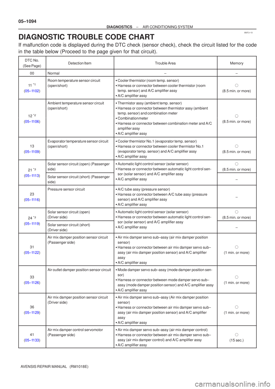
DIAGNOSTIC TROUBLE CODE CHART
If malfunction code is displayed during the DTC check (sensor check), ch\
eck the circuit listed for the code
in the table below (Proceed to the page given for that circuit).
DTC No.
(See Page)Detection ItemTrouble AreaMemory
00Normal±±
11 *1
(05±1102)
Room temperature sensor circuit
(open/short)� Cooler thermistor (room temp. sensor)
� Harness or connector between cooler thermistor (room
temp. sensor) and A/C amplifier assy
� A/C amplifier assy
�
(8.5 min. or more)
12 *2
Ambient temperature sensor circuit
(open/short)� Thermistor assy (ambient temp. sensor)
� Harness or connector between thermistor assy (ambient
temp. sensor) and combination meter
�Combination meter�12
(05±1106)� Combination meter
� Harness or connector between combination meter and A/C
amplifier assy
� A/C amplifier assy�
(8.5 min. or more)
13
(05±1109)
Evaporator temperature sensor circuit
(open/short)� Cooler thermistor No.1 (evaporator temp. sensor)
� Harness or connector between cooler thermistor No.1
(evaporator temp. sensor) and A/C amplifier assy
� A/C amplifier assy
�
(8.5 min. or more)
21 *3
Solar sensor circuit (open) (Passenger
side)� Automatic light control sensor (solar sensor)
� Harness or connector between automatic light control sen-
( l ) d A/C lifi
�
(8.5 min. or more)
21
(05±1113)
Solar sensor circuit (short) (Passenger
side)sor (solar sensor) and A/C amplifier assy
� A/C amplifier assy
±
23
(05±1116)
Pressure sensor circuit� A/C tube assy (pressure sensor)
� Harness or connector between A/C tube assy (pressure
sensor) and A/C amplifier assy
� A/C amplifier assy
±
24 *3
Solar sensor circuit (open)
(Driver side)�Automatic light control sensor (solar sensor)
� Harness or connector between automatic light control sen-
( l ) d A/C lifi
�
(8.5 min. or more)
24
(05±1119)
Solar sensor circuit (short)
(Driver side)sor (solar sensor) and A/C amplifier assy
� A/C amplifier assy
±
31
(05±1122)
Air mix damper position sensor circuit
(Passenger side)� Air mix damper servo sub±assy (air mix damper position
sensor)
� Harness or connector between air mix damper servo sub±
assy (air mix damper position sensor) and A/C amplifier
assy
� A/C amplifier assy
�
(1 min. or more)
33
(05±1126)
Air outlet damper position sensor circuit� Mode damper servo sub±assy (mode damper position sen-
sor)
� Harness or connector between mode damper servo sub±
assy (mode damper position sensor) and A/C amplifier assy
� A/C amplifier assy
�
(1 min. or more)
36
(05±1129)
Air mix damper position sensor circuit
(Driver side)� Air mix damper servo sub±assy (Air mix damper position
sensor)
� Harness or connector between air mix damper servo sub±
assy (air mix damper position sensor) and A/C amplifier
assy
� A/C amplifier assy
�
(1 min. or more)
41
(05±1133)
Air mix damper control servomotor
(Passenger side)� Air mix damper servo sub±assy (air mix damper control)
� Harness or connector between air mix damper servo sub±
assy (air mix damper control) and A/C amplifier assy
� A/C amplifier assy
�
(15 sec.)