Page 1111 of 5135
±
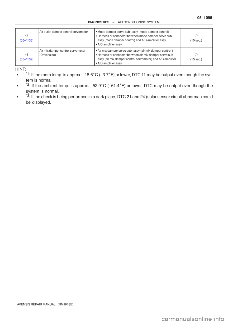
DIAGNOSTICS AIR CONDITIONING SYSTEM
05±1095
AVENSIS REPAIR MANUAL (RM1018E)43
(05±1136)
Air outlet damper control servomotor� Mode damper servo sub±assy (mode damper control)
� Harness or connector between mode damper servo sub±
assy (mode damper control) and A/C amplifier assy
� A/C amplifier assy
�
(15 sec.)
46
(05±1139)
Air mix damper control servomotor
(Driver side)� Air mix damper servo sub±assy (air mix damper control )
� Harness or connector between air mix damper servo sub±
assy (air mix damper control servomotor) and A/C amplifier
� A/C amplifier assy
�
(15 sec.)
HINT:
�*1: If the room temp. is approx. ±18.6 �C (±3.7 �F) or lower, DTC 11 may be output even though the sys-
tem is normal.
�*2: If the ambient temp. is approx. ±52.9 �C (±61.4 �F) or lower, DTC may be output even though the
system is normal.
�*3: If the check is being performed in a dark place, DTC 21 and 24 (solar \
sensor circuit abnormal) could
be displayed.
Page 1117 of 5135
±
DIAGNOSTICS AIR CONDITIONING SYSTEM
05±1089
AVENSIS REPAIR MANUAL (RM1018E)
10 CIRCUIT INSPECTION ( See page 05±1102 to 05± 1159 )
11 IDENTIFICATION OF PROBLEM
12 PARTS INSPECTION
13 REPAIR
14 CONFIRMATION TEST
15 END
Page 1118 of 5135
F44863
D5
DLC3Power Steering
ECU Assy
J/C
TS
CG12
4J8D (*1)
J16
J/CA J20D (*2)
J20D
(*2)J9B
(*1)W (*1) W
Center J/B
CB3
CA6E1511
IO IP *1: LHD
*2 RHD TS
W (*2)
W±B (*2)
W±B (*1)
A W±B (*2)
W±B (*1) 05±1086
± DIAGNOSTICSELECTRONIC MOTOR POWER STEERING SYSTEM
AVENSIS REPAIR MANUAL (RM1018E)
TS TERMINAL CIRCUIT
CIRCUIT DESCRIPTION
After making short circuit between terminal Ts and CG of DLC3 with turning the ignition switch OFF, the mode
will change from the normal mode to test mode when the ignition switch is turned ON. After the ignition switch
is turned ON, there will be DTC output from Tc terminal of DLC3.
WIRING DIAGRAM
050XA±04
Page 1119 of 5135
C52361
Ts
CGDLC3:
±
DIAGNOSTICS ELECTRONIC MOTOR POWER STEERING SYSTEM
05±1087
AVENSIS REPAIR MANUAL (RM1018E)
INSPECTION PROCEDURE
1INSPECT DLC3 TERMINAL VOLTAGE(Ts TERMINAL) (Ts ± CG)
(a)Turn the ignition switch ON.
(b)Measure the voltage between terminals Ts and CG of
DLC3.
OK:
Voltage: 5 to 16 V
OKGo to step 3
NG
2CHECK HARNESS AND CONNECTOR(DLC3 ± BODY GROUND)
(a)Check for an open or short circuit in harness and connector between terminal \
CG of DLC3 and body ground (See page 01±32).
NG REPAIR OR REPLACE HARNESS ORCONNECTOR
OK
3 CHECK HARNESS AND CONNECTOR(POWER STEERING ECU ASSY ± DLC3)
(a) Check for an open or short circuit in harness and connector between terminal \
Ts of DLC3 and power steering ECU assy (See page 01±32).
NG REPAIR OR REPLACE HARNESS ORCONNECTOR
OK
REPLACE POWER STEERING ECU ASSY(See page 50±20)
Page 1120 of 5135
F44864
D5
DLC3Power Steering
ECU Assy
TC13 W±L W±L
J8 J21 J9 J20
(*1) (*2) (*1) (*2)J/C
E15 TC4 B D D B
CG4 W±B (*2) W±B (*2)
CBCenter J/B
3
CA6
W±B (*1)
IO IPA
A J16
J/C
W±B (*1)
*1: LHD
*2: RHD 05±1084
± DIAGNOSTICSELECTRONIC MOTOR POWER STEERING SYSTEM
AVENSIS REPAIR MANUAL (RM1018E)
TC TERMINAL CIRCUIT
CIRCUIT DESCRIPTION
When the terminals Tc and CG of DLC3 are connected, the power steering ECU assy displays the DTC.
WIRING DIAGRAM
050X7±04
Page 1121 of 5135
C52361
TcCGDLC3:
±
DIAGNOSTICS ELECTRONIC MOTOR POWER STEERING SYSTEM
05±1085
AVENSIS REPAIR MANUAL (RM1018E)
INSPECTION PROCEDURE
1INSPECT DLC3 TERMINAL VOLTAGE(Tc TERMINAL)
(a)Turn the ignition switch ON.
(b)Measure the voltage between terminals Tc and CG of
DLC3.
OK:
Voltage: 5 to 16 V
OKGo to step 3
NG
2CHECK HARNESS AND CONNECTOR(DLC3 ± BODY GROUND)
(a)Check for an open or short circuit in harness and connector between terminals\
CG of DLC3 and body ground (See page 01±32).
NG REPAIR OR REPLACE HARNESS ORCONNECTOR
OK
3 CHECK HARNESS AND CONNECTOR(DLC3 ± POWER STEERING ECU ASSY)
(a) Check for an open or short circuit in harness and connector between terminals\
Tc of DLC3 and power steering ECU assy (See page 01±32).
NG REPAIR OR REPLACE HARNESS ORCONNECTOR
OK
REPLACE POWER STEERING ECU ASSY(See page 50±20)
Page 1122 of 5135
F44861
B±W22
C11Combination Meter
Driver Side J/B
Engine Room R/B No.4 Engine Room R/B No.1 and
Engine Room J/B No.1Power Steering
ECU Assy
6
C11
17
C10B±W
W±B
W±B
B±WP/S
J8C
AM2 J26A
J8C
J26A J/C
B±WB±R
B±R B±R B±R
B±RB±GB±G
B±G (*1) (*2) (*1) (*2)(*1)
(*2)
18
DA2
DH IGN
IE41
IP11
(*1) (*2)
1
1A1
111
4A
4B
2AM2 IG2 I13
Ignition SWE159
WL
46
FL MAIN
BatteryJ15
J/CJ16
J/C
IK
IO AA
*1: LHD
*2: RHDA
AJ17
J/C
A W±B
(*2)
W±B
(*1) 05±1082
± DIAGNOSTICSELECTRONIC MOTOR POWER STEERING SYSTEM
AVENSIS REPAIR MANUAL (RM1018E)
EMPS Warning Light Circuit
CIRCUIT DESCRIPTION
If the power steering ECU assy detects a trouble, the PS warning lights up. At this time, the power steering
ECU assy records a DTC in memory.
WIRING DIAGRAM
05C5I±01
Page 1123 of 5135

INSPECTION PROCEDURE
NOTICE:
When performing the inspection of power steeri")
F44851
E14PGND
F44869
E15WL
±
DIAGNOSTICS ELECTRONIC MOTOR POWER STEERING SYSTEM
05±1083
AVENSIS REPAIR MANUAL (RM1018E)
INSPECTION PROCEDURE
NOTICE:
When performing the inspection of power steering ECU, ECU must be instal\
led to the vehicle or fully
fixed.
1CHECK HARNESS AND CONNECTOR(POWER STEERING ECU ASSY ±
COMBINATION METER ASSY)
(a)Check for an open or short circuit in harness and connector between power ste\
ering ECU assy and
combination meter assy (See page 01±32).
NGREPAIR OR REPLACE HARNESS ORCONNECTOR
OK
2CHECK HARNESS AND CONNECTOR(POWER STEERING ECU ASSY ± BODY GROUND)
(a)Disconnect the E14 connector from the power steering
ECU assy.
(b)Check the continuity between the terminal PGND of the
E14 connector and body ground.
Standard:
Continuity
NGREPAIR OR REPLACE HARNESS OR CONNECTOR
OK
3INSPECT POWER STEERING ECU ASSY
(a)Turn the ignition switch ON.
(b)Disconnect the E15 connector from the power steering ECU assy, and check the P/S warning light comes on.
(c)Using a service wire, ground the terminal WL of the E15 connector, and check the P/S warning light goes off.
Standard:
P/S warning light comes on and then goes off
NGREPLACE POWER STEERING ECU ASSY (See page 50±20)
OK
CHECK GO TO COMBINATION METER SYSTEM

10 CIRCUIT INSPECTION ( See page 05±1102 to 05± 1159 )
11 IDENTIFICATION OF PROBLEM
12 PARTS INSPECTION
13 REPAIR")

J16
J/CA J20D (*2)
J20D
(*2)J9B
(*1)W (*1) W
Center J/B
CB3
CA6E1511
IO IP *1: LHD
*2 RHD TS
W (*2)
W±B (*2)
W±B (*1)
A W±B (*2)
W±B (*1")

INSPECTION PROCEDURE
1INSPECT DLC3 TERMINAL VOLTAGE(Ts TERMINAL) (Ts ± CG)
(a)Turn t")
 (*2) (*1) (*2)J/C
E15 TC4 B D D B
CG4 W±B (*2) W±B (*2)
CBCenter J/B
3
CA6
W±B (*1)
IO IPA
A J16
J/C
W±B (*1)
*1: LHD
*2: RH")

INSPECTION PROCEDURE
1INSPECT DLC3 TERMINAL VOLTAGE(Tc TERMINAL)
(a)Turn the ignition")
