Page 1135 of 5135
F44304
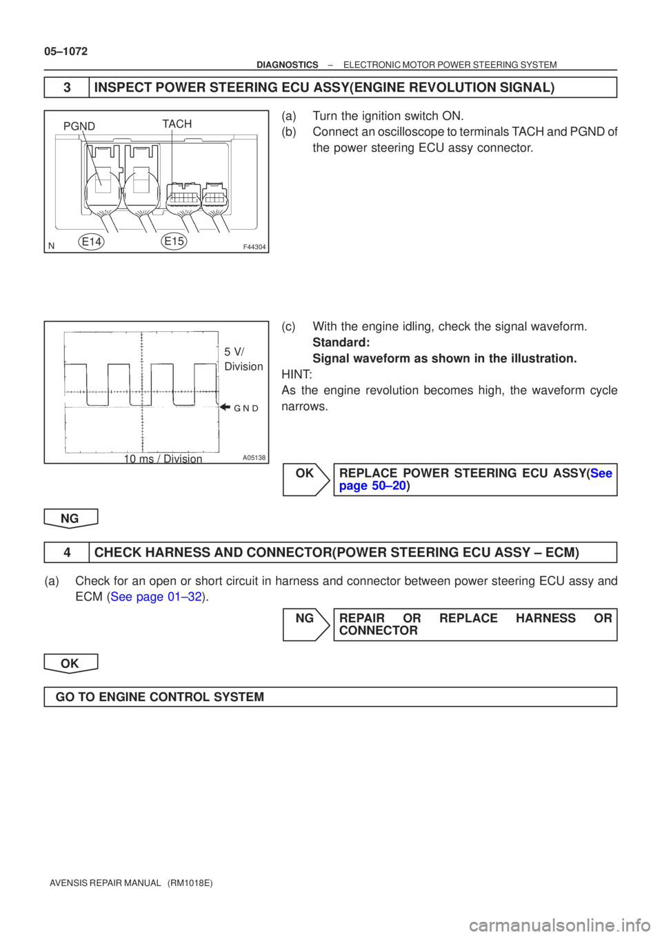
PGNDE14TACH
E15
���
A05138
5 V/
Division
10 ms / Division
05±1072
±
DIAGNOSTICS ELECTRONIC MOTOR POWER STEERING SYSTEM
AVENSIS REPAIR MANUAL (RM1018E)
3INSPECT POWER STEERING ECU ASSY(ENGINE REVOLUTION SIGNAL)
(a)Turn the ignition switch ON.
(b)Connect an oscilloscope to terminals TACH and PGND of the power steering ECU assy connector.
(c)With the engine idling, check the signal waveform. Standard:
Signal waveform as shown in the illustration.
HINT:
As the engine revolution becomes high, the waveform cycle
narrows.
OKREPLACE POWER STEERING ECU ASSY(See page 50±20)
NG
4 CHECK HARNESS AND CONNECTOR(POWER STEERING ECU ASSY ± ECM)
(a) Check for an open or short circuit in harness and connector between powe\
r steering ECU assy and ECM (See page 01±32).
NG REPAIR OR REPLACE HARNESS ORCONNECTOR
OK
GO TO ENGINE CONTROL SYSTEM
Page 1136 of 5135
F44865
Combination Meter Power Steering ECU
C11V±W 18
SPD J10H
J10H
J20H
J20H
E155
V±W
(*1) (*2) (*1) (*2)
*1: LHD
*2: RHDJ/C
± DIAGNOSTICSELECTRONIC MOTOR POWER STEERING SYSTEM
05±1067
AVENSIS REPAIR MANUAL (RM1018E)
DTC C1541/41 Speed Sensor Malfunction
DTC C1542/42 Speed Sensor Malfunction
DTC C1571/71 Speed Sensor Malfunction (Test mode)
CIRCUIT DESCRIPTION
DTC No.DTC Detecting ConditionTrouble Area
C1541/41
Speed sensor malfunction
�Speed sensor
�Speed sensor circuit
C1542/42
Speed sensor malfunction�Speed sensor circuit
�Skid control ECU assy
Cbiti tC1571/71Speed sensor malfunction (Test mode)�Combination meter assy
�Power steering ECU assy
WIRING DIAGRAM
0579L±02
Page 1137 of 5135

INSPECTION PROCEDURE
NOTICE:
When performing the inspection of power steering ECU, ECU must be instal\")
05±1068
±
DIAGNOSTICS ELECTRONIC MOTOR POWER STEERING SYSTEM
AVENSIS REPAIR MANUAL (RM1018E)
INSPECTION PROCEDURE
NOTICE:
When performing the inspection of power steering ECU, ECU must be instal\
led to the vehicle or fully
fixed.
HINT:
Start the inspection from the step 1 with using hand±held tester. Start from step 2 without using hand±held
tester.
1READ VALUE OF HAND±HELD TESTER
(a)Connect the hand±held tester to the DLC3.
(b)Turn the ignition switch to ON, and turn the hand±held tester main swi\
tch to ON.
(c)Select the item ºSPDº in the DATA LIST and read its value displayed on the hand±held tester.
(d)Check that there is no difference between the speed value output from the speedometer displayed by the hand±held tester and the speed value displayed by the speedometer wh\
en driving the vehicle.
OK:
There is almost no difference in the displayed speed values.
HINT:
There is tolerance of �10 % in the speedometer indication.
OKREPLACE POWER STEERING ECU ASSY(Seepage 50±20)
NG
2 CHECK DIAGNOSTIC CODE OUTPUT
(a) Check that DTC for brake system output the normal code. NG REPAIR CIRCUIT INDICATED BY OUTPUTCODE
OK
Page 1138 of 5135
F44304
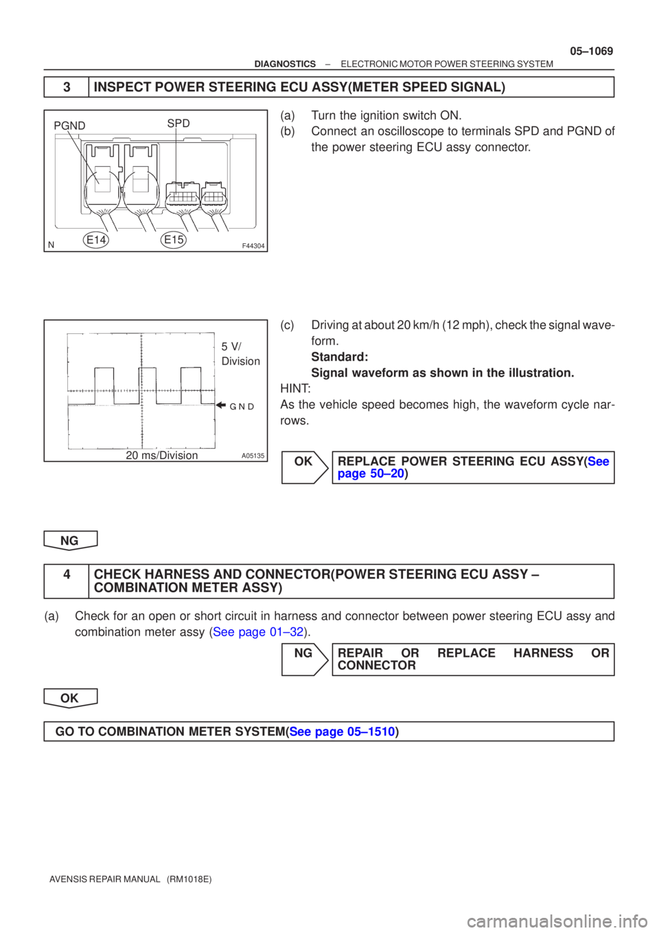
PGNDE14SPD
E15
���
A05135
5 V/
Division
20 ms/Division
±
DIAGNOSTICS ELECTRONIC MOTOR POWER STEERING SYSTEM
05±1069
AVENSIS REPAIR MANUAL (RM1018E)
3INSPECT POWER STEERING ECU ASSY(METER SPEED SIGNAL)
(a)Turn the ignition switch ON.
(b)Connect an oscilloscope to terminals SPD and PGND of
the power steering ECU assy connector.
(c)Driving at about 20 km/h (12 mph), check the signal wave- form.
Standard:
Signal waveform as shown in the illustration.
HINT:
As the vehicle speed becomes high, the waveform cycle nar-
rows.
OKREPLACE POWER STEERING ECU ASSY(See page 50±20)
NG
4 CHECK HARNESS AND CONNECTOR(POWER STEERING ECU ASSY ± COMBINATION METER ASSY)
(a) Check for an open or short circuit in harness and connector between powe\
r steering ECU assy and
combination meter assy (See page 01±32).
NG REPAIR OR REPLACE HARNESS ORCONNECTOR
OK
GO TO COMBINATION METER SYSTEM(See page 05±1510)
Page 1139 of 5135
05±1066
±
DIAGNOSTICS ELECTRONIC MOTOR POWER STEERING SYSTEM
AVENSIS REPAIR MANUAL (RM1018E)
DTCC1531/31EMPS ECU Circuit Malfunction
DTCC1532/32EMPS ECU Circuit Malfunction
DTCC1533/33EMPS ECU Circuit Malfunction
DTCC1534/34EMPS ECU Circuit Malfunction
DTCC1581/81Assist Map Un±written
CIRCUIT DESCRIPTION
DTC No.DTC Detecting ConditionTrouble Area
C1531/31
C1532/32PoersteeringECUassmalfnctionC1533/33Power steering ECU assy malfunctionPower steering ECU assy
C1534/34
gy
C1581/81Assist map un±written
INSPECTION PROCEDURE
1RECONFIRM DTC
(a)Check the DTCs (See page 05±1045).
(b) Is DTC except for C1531/31, C1532/32, C1533/33, C1534/34 and/or C1581/81\
output? YES REPAIR CIRCUIT INDICATED BY OUTPUTCODE
NO
REPLACE POWER STEERING ECU ASSY (See page 50±20)
050WS±04
Page 1140 of 5135
I35378
A23
Air Mix Control Servo Motor (Driver Side) A/C Control Assembly
M
MAX
HOT4P±L
A15 AMDH12
MAX
COOL5B
A15 AMDC11
PT 3GR
A16 TPD8
VZ 2Y±B
A16 S5±22
GND 1Y±R
A15 SG±214
± DIAGNOSTICSAIR CONDITIONING SYSTEM
05±1139
AVENSIS REPAIR MANUAL (RM1018E)
DTC 46 AIR MIX DAMPER CONTROL SERVOMOTOR
CIRCUIT (DRIVER SIDE)
CIRCUIT DESCRIPTION
The air mix damper servo sub±assy is controlled by the A/C amplifier and moves the air mix damper to the
desired position.
DTC No.Detection ItemTrouble Area
46Air mix damper position sensor value does not change even if
A/C amplifier operated air mix damper control servomotor.
�Air mix damper servo sub±assy (air mix damper control )
�Harness or connector between air mix damper servo sub±
assy (air mix damper control servomotor) and A/C amplifier
�A/C amplifier assy
WIRING DIAGRAM
05A8A±02
Page 1141 of 5135
05±1140
±
DIAGNOSTICS AIR CONDITIONING SYSTEM
AVENSIS REPAIR MANUAL (RM1018E)
1PERFORM ACTUATOR CHECK
(a)Set the actuator check mode (See page 05±1091).
(b) Press the DEF switch (driver side) and change to the step operation.
(c) Check the air flow temperature by hand.
Display CodeAir Mix Damper Operation
0COOL side (0 % open)
1COOL side (0 % open)
2COOL side (0 % open)
3COOL side (0 % open)
4COOL/HOT (50% open)
5COOL/HOT (50% open)
6HOT side (100% open)
7HOT side (100% open)
8HOT side (100% open)
9HOT side (100% open)
NG PROCEED TO NEXT CIRCUIT INSPECTION SHOWN ON PROBLEM SYMPTOMS TABLE
OK
Page 1142 of 5135
I35383
RHD Models:
MAX. COOL MAX. HOT
1
2
3
4
5
MAX HOTMAX COOL
I36141
LHD Models:
MAX. COOL MAX. HOT
MAX HOTMAX COOL
±
DIAGNOSTICS AIR CONDITIONING SYSTEM
05±1141
AVENSIS REPAIR MANUAL (RM1018E)
2INSPECT AIRMIX DAMPER SERVO SUB±ASSY
(a)Remove the air mix damper servo sub±assy.
(b)Connect the positive (+) lead from the battery to terminal
MAX HOT and negative (±) lead to terminal MAX COOL,
then check that the lever turns to ºHOTº side smoothly.
(c)Connect the positive (+) lead from the battery to terminal MAX COOL and negative (±) lead to terminal MAX HOT,
then check that the lever turns to ºCOOLº side smoothly.
NGREPLACE AIRMIX DAMPER SERVO SUB±ASSY
OK
3CHECK HARNESS AND CONNECTOR(AIRMIX DAMPER SERVO SUB±ASSY ± A/C AMPLIFIER)
(a)Check for an open or short circuit in harness and connector between air mix c\
ontrol servomotor and
A/C amplifier (See page 01±32).
NG REPAIR OR REPLACE HARNESS ORCONNECTOR
OK
REPLACE AIR CONDITIONING AMPLIFIER
 (*2) (*1) (*2)
*1: LHD
*2: RHDJ/C
± DIAGNOSTICSELECTRONIC MOTOR POWER STEERING SYSTEM
05±1067
AVENSIS RE")

DTCC1531/31EMPS ECU Circuit Malfunction
DTCC1532/32EMPS ECU Circuit Malfunction
DTCC1533/33EMPS ECU Cir")
 A/C Control Assembly
M
MAX
HOT4P±L
A15 AMDH12
MAX
COOL5B
A15 AMDC11
PT 3GR
A16 TPD8
VZ 2Y±B
A16 S5±22
GND 1Y±R
A15 SG±214
± DIAGNOSTICSAIR CO")

1PERFORM ACTUATOR CHECK
(a)Set the actuator check mode (See page 05±1091).
(b) Press the DEF switch (driver side) and")
")